Blog

  • IoT Based Hydroponics System Project Design

    IoT Based Hydroponics System Project Design

    This IoT based hydroponics system project design was designed to monitor and control a hydroponics farm. The scope of the project is to measure the pH, TDS value, humidity, air temperature, and water temperature of the nutrient solution. The project also automatically pumps water into the base nutrient bucket when the temperature is somewhat high or when the water level gauge says the water level is too low.

    Materials for this Project:

    Atmega328P-Pu microcontroller:
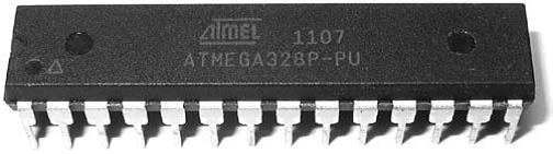
    The microcontroller for IoT Based Hydroponics System Project Design
    Atmega328P-PU IC

    The Atmega328P-PU microcontroller was the type of 28-pin AVR chip used to program, sense, monitor, and control all the sensors used in the construction of this project. It is the brain of the project because it reads the analog sensors with its analog IO pins, sends serials communications and displays results also on the display modules

    16MHz Crystal Oscillator:
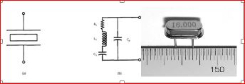
    IoT Based Hydroponics System Project Design
    16mHz CRYSTAL OSCILLATOR

    More commonly known as simply a crystal, the crystal oscillator creates an electrical signal with a very accurate frequency. In this case, the frequency is 16 MHz Crystals are not polarized. The schematic symbol is shown in Figure 3.12. The crystal determines the microcontroller’s speed of operation. For example, the microcontroller circuit we’ll be assembling runs at 16 MHz, which means it can execute 16 million processor instructions per second. That doesn’t mean it can execute a line of sketch or a function that rapidly, however, since it takes many processor instructions to interpret a single line of code.

    22pF capacitors:
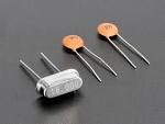
    crystal oscillator and 22pF capacitor
    16MHz crystal with 22pF capacitors

    Perforated boards:

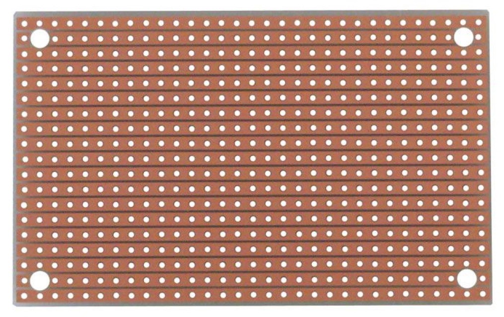
    perboard
    strip board for soldering contructed boards

    Dallas temperature sensor DS18B20:

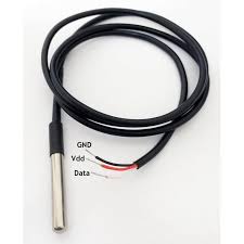
    IoT Based Hydroponics System Project Design: the temperature sensor
    ds18b20 temperature sensor

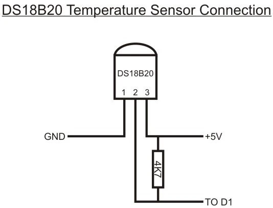
    The DS18B20 digital thermometer provides 9-bit to 12-bit Celsius temperature measurements and has an alarm function with nonvolatile, user-programmable upper and lower trigger points. The DS18B20 communicates over a 1-Wire bus that, by definition, requires only one data line (and ground) for communication with a central microprocessor. In addition, the DS18B20 can derive power directly from the data line (“parasite power”), eliminating the need for an external power supply.  Each DS18B20 has a unique 64-bit serial code, which allows multiple DS18B20s to function on the same 1-Wire bus. Thus, it is simple to use one microprocessor to control many DS18B20s distributed over a large area. Applications that can benefit from this feature include HVAC environmental controls, temperature monitoring systems inside buildings, equipment, or machinery, and process monitoring and control systems. We just used it to to measure temperature in this IoT Based Hydroponics System Project Design.

    5V Single Channel Relay Module:
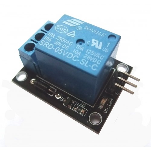
    Single Channel Relay Module for IoT Based Hydroponics System Project Design
    single channel relay module

    A relay is used to turn on and turn off the power supply that energizes the solenoid valve which pumps water into the hydroponic farm. Relay gets the control signal from microcontroller through a transistor( an SMD type). A diode is use in parallel with the coil pin of relay to avoid sparking in case of back EMF; because the coil is made of inductive material. The selection of the relay depended on load of our system. For example, for a maximum load of our home devices say, 10 Amperes. Another important thing considered while selecting relay for this project was switching speed of relay. The relay speed was noticed to be as fast as possible. Because the more the switching speed of relay, the more protection it will provide to the load devices when turning them on or off in minimum possible time.

    pH Sensor :
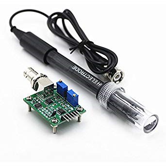
    pH sensor for IoT Based Hydroponics System Project Design
    pH sensor

    Gravity Analog TDS Sensor:

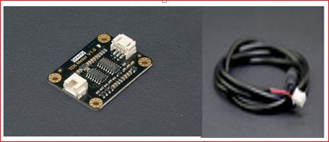
    TDS sensor module kit for IoT Based Hydroponics System Project Design
    TDS sensor module and probe

    The Total Dissolved Solid sensor was used in place of the Electrical Conductivity (EC) sensor because of its relatively low cost compared to the EC sensor. Also, because there is  a conversion scale between the EC sensor and the TDS sensor. This means that we could convert the reading of the TDS from its analog value to the reading in parts per million (ppm). This  is an AVR microcontroller-compatible TDS sensor/Meter Kit for measuring the TDS value of the hydroponic water. It was used to reflect the cleanliness of the water; and conduct our water quality testing for the hydroponic culture. The module sensor supports 3.3–5.5V wide range voltage input and 0–2.3V analog voltage output, which makes it compatible with 5V or 3.3V control systems or development boards. The excitation source is an AC signal, which can effectively prevent the probe from polarization and prolong the lifetime of the probe. Also,  increase the output signal’s stability. The TDS probe is waterproof, it can e immersed in water for a long time for measurement. However, the probe should not be used in water with temperatures above 55 °C. Again, the probe touching the container affects the reading of the TDS sensor.

    20×4 Liquid Crystal Display (LCD):
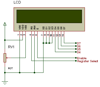
    LCD diagram for IoT Based Hydroponics System Project Design

    An LCD is an electronic display module which uses liquid crystal to produce a visible image. The 20×4 LCD display is a very basic module commonly used in DIYs and circuits. It was used in a 4-bit configuration interfacing with the MCU. The 20×4 translates on a display 20 characters per line in 4 of such lines. In this LCD, each character is displayed in a 5×7-pixel matrix.  This is the visual output where all the commands made and decisions taken by the ‘brain’, the microcontroller unit (MCU) are displayed. It has 16 special pins that are mapped out for special functions.

    The ESP-01 Wi-Fi Module
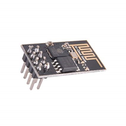
    ESP8266-01 WiFi module

    Relative Humidity and Temperature Sensor (DHT11):
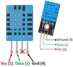
    DHT11 sensor for IoT Based Hydroponics System Project Design

    The DHT11 is a low cost  digital humidity and temperature (DHT). This sensor is very basic and slow, but it is great for some basic data logging. The DHT11 sensor is made of two parts, a capacitive humidity sensor and a thermistor. There is also a very basic chip inside that does some analog-to-digital conversion and spits out a digital signal with the temperature and humidity. The digital signal is fairly easy to read using any microcontroller.

    IoT Based Hydroponics System Project Design: THE CIRCUIT DIAGRAM
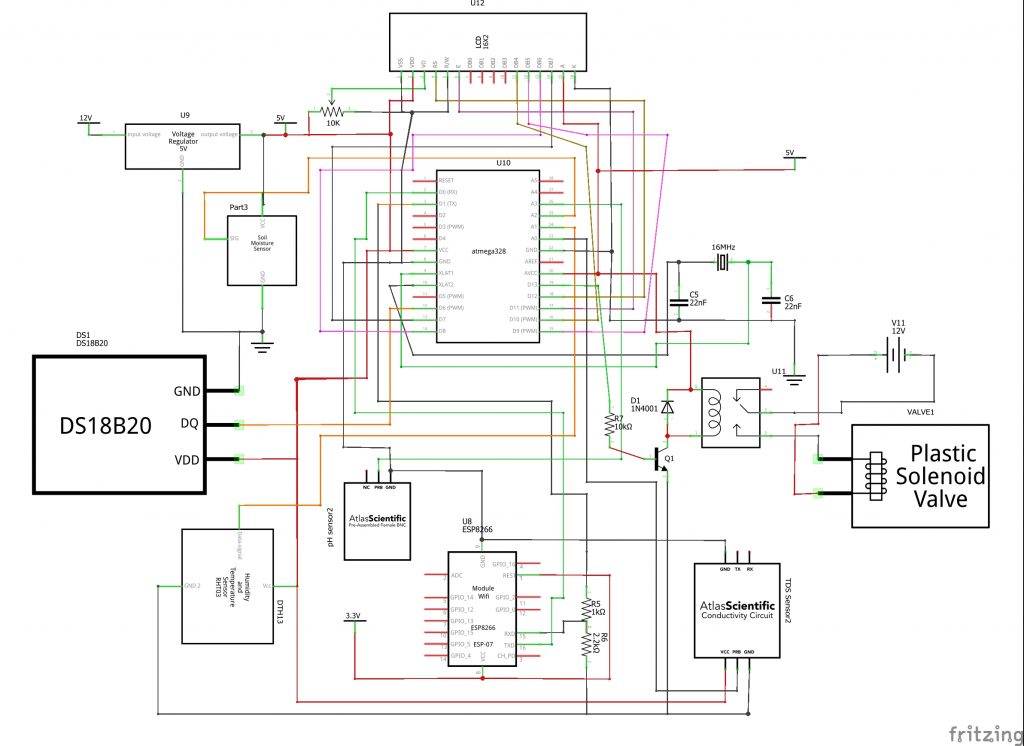
    IoT Based Hydroponics System Project Design
    circuit diagram for the complete design

    IoT Based Hydroponics System Project Design: Circuit Diagram Explanation

    This circuit diagram was designed using Fritzing IDE. The whole circuitry was built around the Atmega328P microcontroller chip. The plastic solenoid valve was used to to irrigate the model farm; this was connected to an external 12V Dc power supply using the single channel relay. This single channel relay was controlled by the digital pin 13 of the Atmeag328P chip.

    Since the power supply is already rated 12V (chosen primarily because of the solenoid valve), a voltage regulator (a better alternative is a DC-DC buck converter) was used to step down the voltage to 5V. This was connected to the microcontroller and and the rest of the sensors.

    Construction of the Circuit
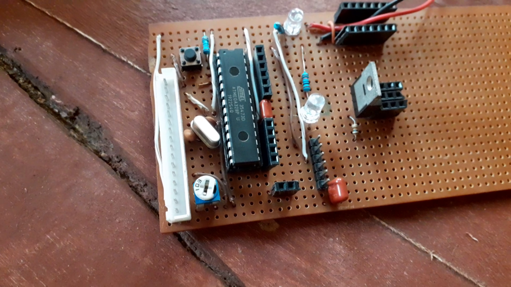
    Construction of IoT Based Hydroponics System Project Design
    The microcontroller constructed
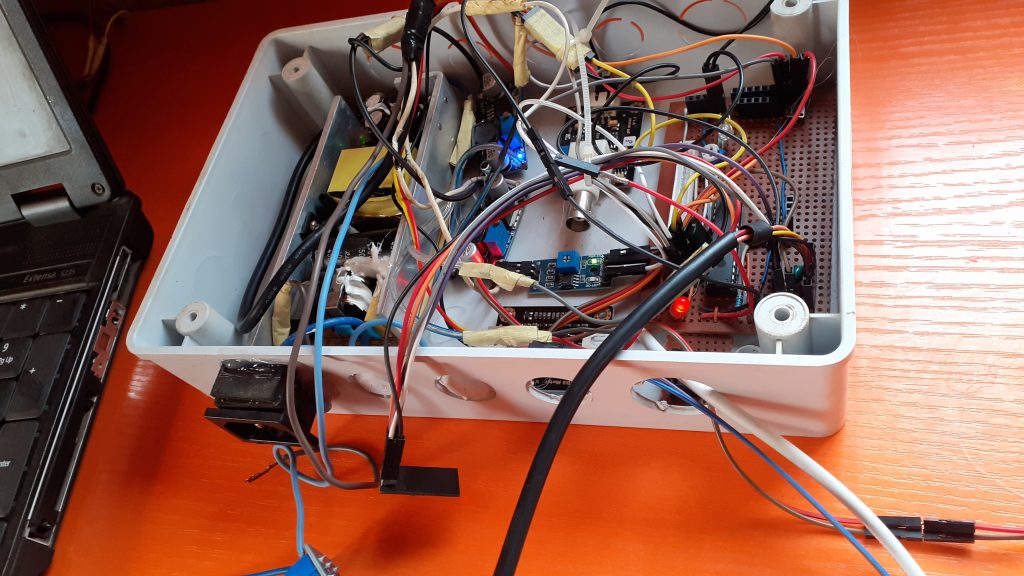
    Casing the IoT Based Hydroponics System Project Design
    all sensors and power modules connected tot he MCu

    PROGRAMMING THE DESIGN.

    #include <SoftwareSerial.h>
    SoftwareSerial EspSerial(2, 3);
    
    String statusChWriteKey = "xxxxxxxxxxxxxxxxx";
    #define HARDWARE_RESET 4
    
    long writeTimingSeconds = 17;
    long startWriteTiming = 0;
    long elapsedWriteTime = 0;
    
    #include <DallasTemperature.h>
    #include <OneWire.h>
    #include "DHT.h"
    // include the library code:
    #include <LiquidCrystal.h>
    
    #define ONE_WIRE_BUS 6
    #define DHTPIN A0
    OneWire oneWire(ONE_WIRE_BUS);
    DallasTemperature sensors(&oneWire);
    
    boolean error;
    
    #define SensorPin A3            //pH meter Analog output to Arduino Analog Input 0
    #define Offset 0.00            //deviation compensate
    #define DHTTYPE DHT11   // DHT 11
    #define LED 13


    LiquidCrystal lcd(12, 11, 10, 9, 8, 7);
    
    
    #define TdsSensorPin A1
    #define VREF 5.0      // analog reference voltage(Volt) of the ADC
    #define SCOUNT  30           // sum of sample point
    int analogBuffer[SCOUNT];    // store the analog value in the array, read from ADC
    int analogBufferTemp[SCOUNT];
    int analogBufferIndex = 0,copyIndex = 0;
    float averageVoltage = 0,tdsValue = 0,temperature = 25;
    
    DHT dht(DHTPIN, DHTTYPE);
    #define samplingInterval 20
    #define printInterval 800
    #define ArrayLenth  40    //times of collection
    int pHArray[ArrayLenth];   //Store the average value of the sensor feedback
    int pHArrayIndex=0;
    
     float Celcius=0;
     float Fahrenheit=0;
     float h,t,f;
     static float pHValue,voltage;
     float newPH;
    
    int pumpStatus;
    int waterSense;
    int alarmSense;
     
    void setup(void)
    {
      EspSerial.begin(9600);
      Serial.begin(9600);
      Serial.begin(115200);
      pinMode(HARDWARE_RESET, OUTPUT);
      digitalWrite(HARDWARE_RESET, HIGH);
      EspHardwareReset();
      startWriteTiming = millis();
      pinMode(LED,OUTPUT);
      pinMode(TdsSensorPin,INPUT);
      pinMode(A5, OUTPUT);
      pinMode(A4, OUTPUT);
    
      analogWrite(A4, 255);
      analogWrite(A5, 0);
      
         sensors.begin();
      Serial.println("pH meter experiment!");    //Test the serial monitor
       Serial.println(F("DHTxx test!"));
    dht.begin();
    //begin the lcd sensor
       sensors.begin();
       lcd.begin(20, 4);
       lcd.setCursor(0, 0);
       lcd.print("   WELCOME JALANI");
       lcd.setCursor(0, 1);
       lcd.print("  SMART HYDROPONIC");
       lcd.setCursor(0, 2);
       lcd.print(" INTERNET OF THINGS");
       lcd.setCursor(0, 3);
       lcd.print("      PROJECT");
            delay(3000);
       lcd.clear();
       
       lcd.setCursor(0, 0);
       lcd.print("       PLS ");
       lcd.setCursor(0, 1);
       lcd.print("     GIVE TIME ");
       lcd.setCursor(0, 2);
       lcd.print("  FOR THE SENSORS ");
       lcd.setCursor(0, 3);
       lcd.print("     TO BOOTH ");
       delay(2000);
       lcd.clear();
       
     lcd.setCursor(1, 0);
     lcd.print("TEMP");
     lcd.setCursor(9, 0);
     lcd.print("TDS");
     lcd.setCursor(18, 0);
     lcd.print("pH");
     
     lcd.setCursor(0, 2);
     lcd.print("W.LEVEL");
     lcd.setCursor(9, 2);
     lcd.print("HUM");
     lcd.setCursor(14, 2);
     lcd.print("A.TEMP");
       
    }
    
    
    void waterLevel(){
      waterSense= analogRead(A2);
      Serial.println(waterSense);
      //print out on LCD
     lcd.setCursor(0, 3);
     lcd.print(waterSense);
     //lcd.setCursor(3, 3);
     //lcd.print("cm");  
      delay(500);
      
       if(waterSense > 500){
        analogWrite(A4, 0);
       }
    
       if(waterSense <= 240){
        analogWrite(A4, 255);
       }
       
    }
    
    void humSensor(){
      // Wait a few seconds between measurements.
      delay(2000);
    
      // Reading temperature or humidity takes about 250 milliseconds!
      // Sensor readings may also be up to 2 seconds 'old' (its a very slow sensor)
      h = dht.readHumidity();
      // Read temperature as Celsius (the default)
      t = dht.readTemperature();
      // Read temperature as Fahrenheit (isFahrenheit = true)
       f = dht.readTemperature(true);
    
      // Check if any reads failed and exit early (to try again).
      if (isnan(h) || isnan(t) || isnan(f)) {
        Serial.println(F("Failed to read from DHT sensor!"));
        return;
      }
    
      // Compute heat index in Fahrenheit (the default)
      float hif = dht.computeHeatIndex(f, h);
      // Compute heat index in Celsius (isFahreheit = false)
      float hic = dht.computeHeatIndex(t, h, false);
    
      lcd.setCursor(8, 3);
      lcd.print(h);
      lcd.setCursor(15, 3);
      lcd.print(t);
    
      if(h <= 10.00){
        analogWrite(A5, 255);
        lcd.clear();
        lcd.setCursor(0, 0);
        lcd.print("AIR TOO DRY");
      }
      else {
        
      }
    
      Serial.print(F("Humidity: "));
      Serial.print(h);
      Serial.print(F("%  Temperature: "));
      Serial.print(t);
      Serial.print(F("°C "));
      Serial.print(f);
      Serial.print(F("°F  Heat index: "));
      Serial.print(hic);
      Serial.print(F("°C "));
      Serial.print(hif);
      Serial.println(F("°F"));
    }
    
    void pH(){
      static unsigned long samplingTime = millis();
      static unsigned long printTime = millis();
      if(millis()-samplingTime > samplingInterval)
      {
          pHArray[pHArrayIndex++]=analogRead(SensorPin);
          if(pHArrayIndex==ArrayLenth)pHArrayIndex=0;
          voltage = avergearray(pHArray, ArrayLenth)*5.0/1024;
          pHValue = 3.5*voltage+Offset;
          samplingTime=millis();
      }
      if(millis() - printTime > printInterval)   //Every 800 milliseconds, print a numerical, convert the state of the LED indicator
      {
        Serial.print("Voltage:");
            Serial.print(voltage,2);
                    newPH = pHValue + 5.60;
            newPH = map(newPH, 0.00, 14.00, 1.00, 14.00);
            Serial.print("    pH value: ");
        Serial.println(newPH,2);
    
        lcd.setCursor(17, 1);
     lcd.print(newPH);
     
        digitalWrite(LED,digitalRead(LED)^1);
        printTime=millis();
      }
    }
    double avergearray(int* arr, int number){
      int i;
      int max,min;
      double avg;
      long amount=0;
      if(number<=0){
        Serial.println("Error number for the array to avraging!/n");
        return 0;
      }
      if(number<5){   //less than 5, calculated directly statistics
        for(i=0;i<number;i++){
          amount+=arr[i];
        }
        avg = amount/number;
        return avg;
      }else{
        if(arr[0]<arr[1]){
          min = arr[0];max=arr[1];
        }
        else{
          min=arr[1];max=arr[0];
        }
        for(i=2;i<number;i++){
          if(arr[i]<min){
            amount+=min;        //arr<min
            min=arr[i];
          }else {
            if(arr[i]>max){
              amount+=max;    //arr>max
              max=arr[i];
            }else{
              amount+=arr[i]; //min<=arr<=max
            }
          }//if
        }//for
        avg = (double)amount/(number-2);
      }//if
      return avg;
    }
    
    
    void TDS(){
      static unsigned long analogSampleTimepoint = millis();
       if(millis()-analogSampleTimepoint > 40U)     //every 40 milliseconds,read the analog value from the ADC
       {
         analogSampleTimepoint = millis();
         analogBuffer[analogBufferIndex] = analogRead(TdsSensorPin);    //read the analog value and store into the buffer
         analogBufferIndex++;
         if(analogBufferIndex == SCOUNT) 
             analogBufferIndex = 0;
       }   
       static unsigned long printTimepoint = millis();
       if(millis()-printTimepoint > 800U)
       {
          printTimepoint = millis();
          for(copyIndex=0;copyIndex<SCOUNT;copyIndex++)
            analogBufferTemp[copyIndex]= analogBuffer[copyIndex];
          averageVoltage = getMedianNum(analogBufferTemp,SCOUNT) * (float)VREF / 1024.0; // read the analog value more stable by the median filtering algorithm, and convert to voltage value
          float compensationCoefficient=1.0+0.02*(temperature-25.0);    //temperature compensation formula: fFinalResult(25^C) = fFinalResult(current)/(1.0+0.02*(fTP-25.0));
          float compensationVolatge=averageVoltage/compensationCoefficient;  //temperature compensation
          tdsValue=(133.42*compensationVolatge*compensationVolatge*compensationVolatge - 255.86*compensationVolatge*compensationVolatge + 857.39*compensationVolatge)*0.5; //convert voltage value to tds value
          //Serial.print("voltage:");
          //Serial.print(averageVoltage,2);
          //Serial.print("V   ");
          Serial.print("TDS Value:");
          Serial.print(tdsValue,0);
          Serial.println("ppm");
          
          lcd.setCursor(8, 1);
     lcd.print(tdsValue);
     lcd.setCursor(13, 1);
     lcd.print("ppm");
       }
    }
    int getMedianNum(int bArray[], int iFilterLen) 
    {
          int bTab[iFilterLen];
          for (byte i = 0; i<iFilterLen; i++)
          bTab[i] = bArray[i];
          int i, j, bTemp;
          for (j = 0; j < iFilterLen - 1; j++) 
          {
          for (i = 0; i < iFilterLen - j - 1; i++) 
              {
            if (bTab[i] > bTab[i + 1]) 
                {
            bTemp = bTab[i];
                bTab[i] = bTab[i + 1];
            bTab[i + 1] = bTemp;
             }
          }
          }
          if ((iFilterLen & 1) > 0)
        bTemp = bTab[(iFilterLen - 1) / 2];
          else
        bTemp = (bTab[iFilterLen / 2] + bTab[iFilterLen / 2 - 1]) / 2;
          return bTemp;
    }
    
    void loop(void)
    {
      sensors.requestTemperatures(); 
      Celcius=sensors.getTempCByIndex(0);
      Fahrenheit=sensors.toFahrenheit(Celcius);
       Serial.print(Celcius);
        Serial.print(" 'C  ");
    
       if(Celcius >= 85.00){
        analogWrite(alarmSense, 255);
        lcd.clear();
        lcd.setCursor(0, 0);
        lcd.print("TEMP TO HIGH!");
       }
       else{
        
       }
         lcd.setCursor(0, 1);
     lcd.print(Celcius);
     lcd.setCursor(5, 1);
     lcd.print("'C");
     Serial.println(Celcius);
     delay(500);
     
      waterLevel();
       pH();
     humSensor();
      TDS(); 
      
    int pumpStatus = analogRead(A4);
    int alarmSense = analogRead(A5);
    
      //start: //label 
      //error=0;
      
      elapsedWriteTime = millis()-startWriteTiming; 
      
      if (elapsedWriteTime > (writeTimingSeconds*1000)) 
      {
           writeThingSpeak();
        startWriteTiming = millis();   
      }
      
      if (error==1) //Resend if transmission is not completed 
      {       
        Serial.println(" <<<< ERROR >>>>");
        delay (2000);  
        //goto start; //go to label "start"
      }
     }
    
     void writeThingSpeak(void)
    {
      startThingSpeakCmd();
      // preparacao da string GET
      String getStr = "GET /update?api_key=";
      getStr += statusChWriteKey;
      getStr +="&field1=";
      getStr += String(t);
     getStr +="&field2=";
      getStr += String(h);
       getStr +="&field3=";
      getStr += String(Celcius);
      getStr +="&field4=";
      getStr += String(newPH);
      getStr +="&field5=";
      getStr += String(tdsValue);
      getStr +="&field6=";
      getStr += String(waterSense);
      getStr +="&field7=";
      //getStr += String(pumpStatus);
      getStr +="&field8=";
      //getStr += String(alarmSense);  
      getStr += "rnrn";
      sendThingSpeakGetCmd(getStr);
    }
    
    void EspHardwareReset(void)
    {
      Serial.println("Reseting......."); 
      digitalWrite(HARDWARE_RESET, LOW); 
      delay(500);
      digitalWrite(HARDWARE_RESET, HIGH);
      delay(8000);//Tempo necessário para começar a ler 
      Serial.println("RESET"); 
    }
    /********* Start communication with ThingSpeak*************/
    void startThingSpeakCmd(void)
    {
      EspSerial.flush();//limpa o buffer antes de começar a gravar
      
      String cmd = "AT+CIPSTART="TCP","";
      cmd += "184.106.153.149"; // Endereco IP de api.thingspeak.com
      cmd += "",80";
      EspSerial.println(cmd);
      Serial.print("enviado ==> Start cmd: ");
      Serial.println(cmd);
      if(EspSerial.find("Error"))
      {
        Serial.println("AT+CIPSTART error");
        return;
      }
    }
    /********* send a GET cmd to ThingSpeak *************/
    String sendThingSpeakGetCmd(String getStr)
    {
      String cmd = "AT+CIPSEND=";
      cmd += String(getStr.length());
      EspSerial.println(cmd);
      Serial.print("enviado ==> lenght cmd: ");
      Serial.println(cmd);
      if(EspSerial.find((char *)">"))
      {
        EspSerial.print(getStr);
        Serial.print("enviado ==> getStr: ");
        Serial.println(getStr);
        delay(500);//tempo para processar o GET, sem este delay apresenta busy no próximo comando
        String messageBody = "";
        while (EspSerial.available()) 
        {
          String line = EspSerial.readStringUntil('n');
          if (line.length() == 1) 
          { //actual content starts after empty line (that has length 1)
            messageBody = EspSerial.readStringUntil('n');
          }
        }
        Serial.print("MessageBody received: ");
        Serial.println(messageBody);
        return messageBody;
      }
      else
      {
        EspSerial.println("AT+CIPCLOSE");     // alert user
        Serial.println("ESP8266 CIPSEND ERROR: RESENDING"); //Resend...
        //spare = spare + 1;
        error=1;
        return "error";
      }
    }
    

    The above sketch is to be uploaded into the standalone board using the Arduino IDE and then the next is to configure Thingspeak DB and create an app using MIT AppInventor.

    Configuring Thingspeak IoT DashBoard
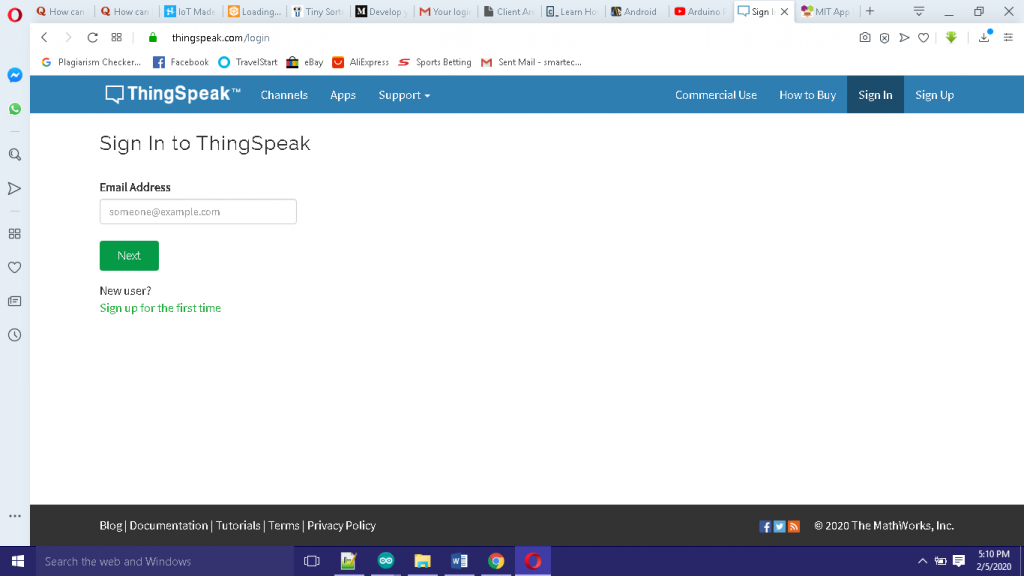
    Thingspeak dashboard for IoT Based Hydroponics System Project Design
    create a thingspeak account and log in

    To use thingspeak database, we need to create a Matlab account. Simply sign up on their website; After signing up, verify your email and sign in.
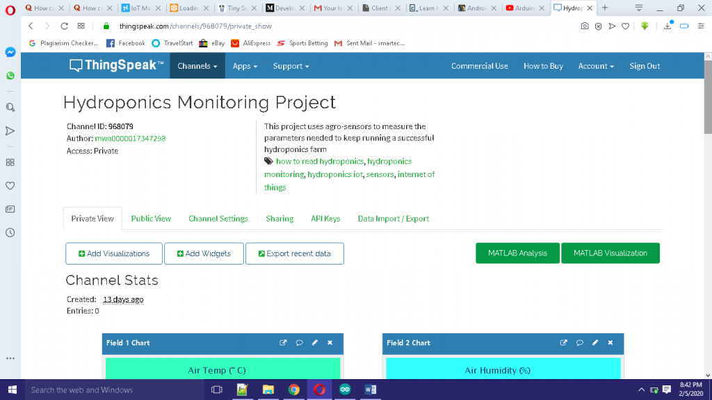
    Thingspeak channel
    name your project and set up the platform

    Once signed in, create a channel. Name your channel. Copy and safely store the API Write Key and the API Read Key. You can allocate your channel to any number of fields or charts. For us, we used 8 fields: 6 for sensors and 2 for actuators.
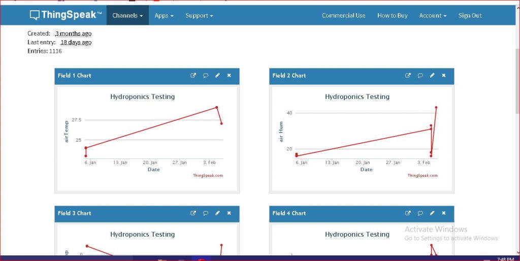
    Thingspeak field charts
    The fields showing readings of each sensors assigned to it.

    After changing the API Write Key in your sketch, upload the code to see this working on the thingspeak channel you made.

    MIT AppInventor

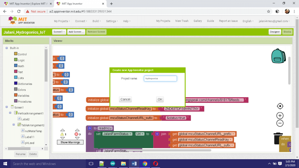
    Next go to MIT app inventor website to create your app. After signing in, you can just import our already made .aia file into your project. You can edit any part of it to your taste. Just make sure to change the API write key to your own.
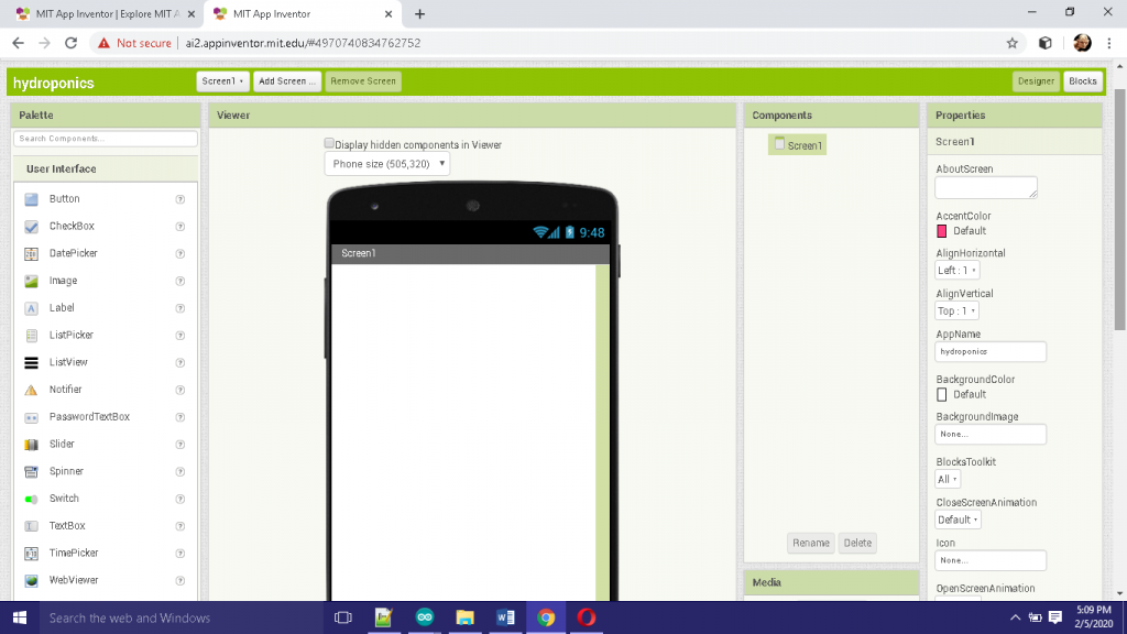
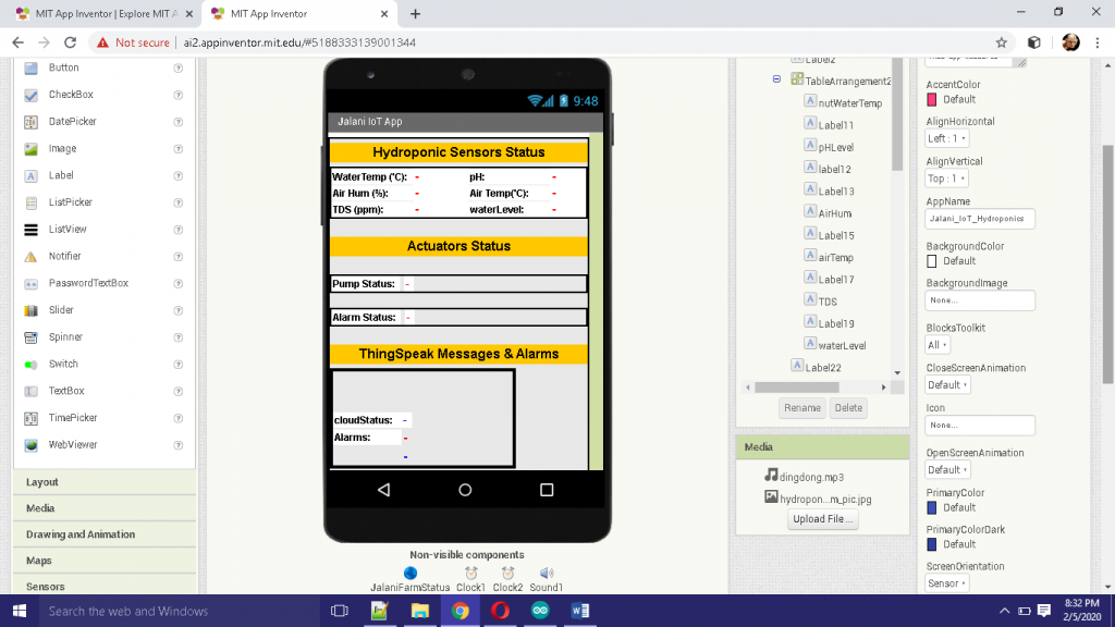
    creating app for  IoT Based Hydroponics System Project Design
    app inventor designer page for the app outlook
     IoT Based Hydroponics System Project Design
    When completing the designs on the app
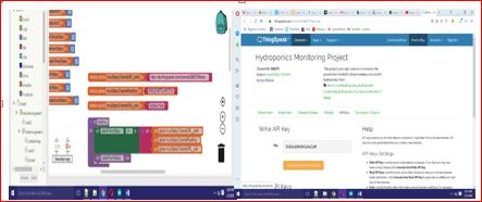
     IoT Based Hydroponics System Project Design: backend code block for appinventor
    The block side of the app
     IoT Based Hydroponics System Project Design
    checking the API Read Key authenticity

    Once the app is done, you could either use the emulator to test it or build it and copy it to your Android phone for installation. After running the app, you can compare the reading with those updates on Thingspeak DB.

    Now the sensor and actuator states can be viewed anywhere around the globe using a web app or a mobile app.

    But also the actuators, the solenoid pump is meant to automatically pump water into the base bucket when the water level is too low, and the alarm is meant to go off when the temperature is too high. The threshold for this state can be adjusted in the sketch above.

    A visual tutorial is given in the YouTube video below.

    tutorial video

    I hope this project tutorial helps you.
    Read More

  • Remote Gate Opener DIY

    Remote Gate Opener DIY

    Ever wished you could open your gate without stepping out of your car?
    Imagine driving home on a rainy day, pressing a button, and your gate slides open like magic. That’s the beauty of a Remote Gate Opener DIY project. It gives you comfort, security, and that futuristic vibe — without spending huge money on commercial systems.

    The good news?
    You can build one yourself. Yes, you. And it’s easier than you think.

    Whether you’re a beginner in electronics or a seasoned DIY lover, this guide walks you through everything you need to know. No complicated jargon. No confusing diagrams. Just a simple, clear, and practical explanation of how to create your own remote-controlled gate opener.

    How It Works

    Let’s break it down in plain language.

    1. You press a button on the remote.
    2. The remote sends a wireless RF signal.
    3. The receiver picks up the signal.
    4. The relay switches ON.
    5. The motor runs and moves the gate.
    6. Limit switches stop the motor when the gate reaches its destination.

    It’s simple, efficient, and works reliably.

    Components Needed

    • Atmega328P-PU
    • 16Mhz Crystal oscillator
    • L293D motor driver IC (or Module)
    • Pushbutton
    • 100nF caps (2 pcs)
    • Male and female header pins
    • 22pF caps (ceramic types, 2 pcs)
    • LEDs (red and green colors)
    • 10k ans 1k precision resistors
    • 16×2 LCD module, socket headers and wire
    • 10k potentiometer
    • MP3 car remote control
    • Pair of DVD/CD ROM
    • Infrared Obstacle Avoidance Sensor Module
    • Infrared (IR) Receiver TSOP1838

    Buy All components on our online store

    Motor-Driven Mechanism (Gating system)

    This is made up of CD tray, DC motor and drive belt from an old DVD player machine.

    remote gate opener project
    The CD ROM and its mechanism

    The low cost nature and its availability made it very useful in its selection. We used two of these devices to control the closing and opening of the gate system. The amazing part of these devices is that each mechanism has a “stopper switch” buried beneath the tray that moves to cut power to the DC motor driving the drive belt that in turns moves the tray. This stopper switch’s state changes in any direction it moves. When it is full forward direction, the stopper switch is LOW and when it is full reverse direction, the switch moves to HIGH. We used these change in states to control our gating system

    remote gate opener project
    this switch is found underneath the CD ROM mechanism

    Also, the drive belt between the DC motor and the gears that control the CD tray doesn’t maintain a very firm grip on the both gear and DC motor. This is very good so that once the tray has gotten to the marked position and by some reasons unknown, the DC motor is still power, the immovable action on the tray won’t cause the DC motor to get over heated and burn out.

    Using L293D Motor Driver IC for Remote Gate Opener Project

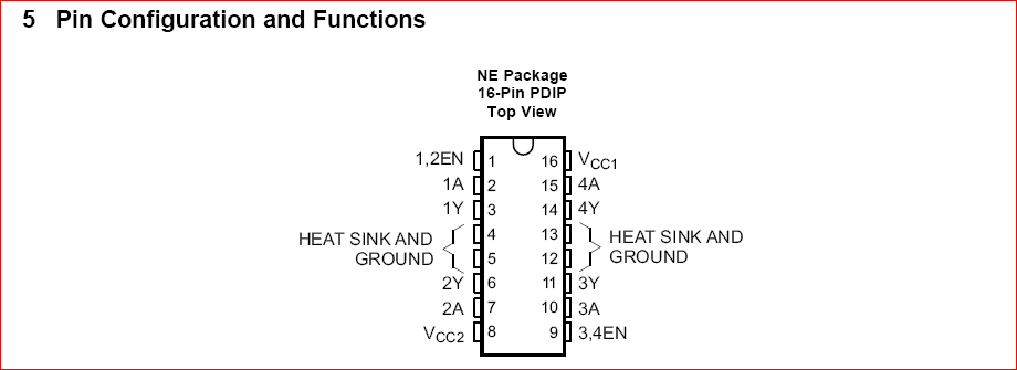
    This integrated circuitry makes it very possible for us to control the motion of the gating system (which involves two DC motors) simultaneously. The L293D is a device that is quadruple high current half-H drivers. With bidirectional drive currents up to 1A at voltages from 4.5V to 36V. This makes it ideal for relays, solenoids, DC and stepper motors.

    L293D Motor Driver IC
    L293D pinout diagram

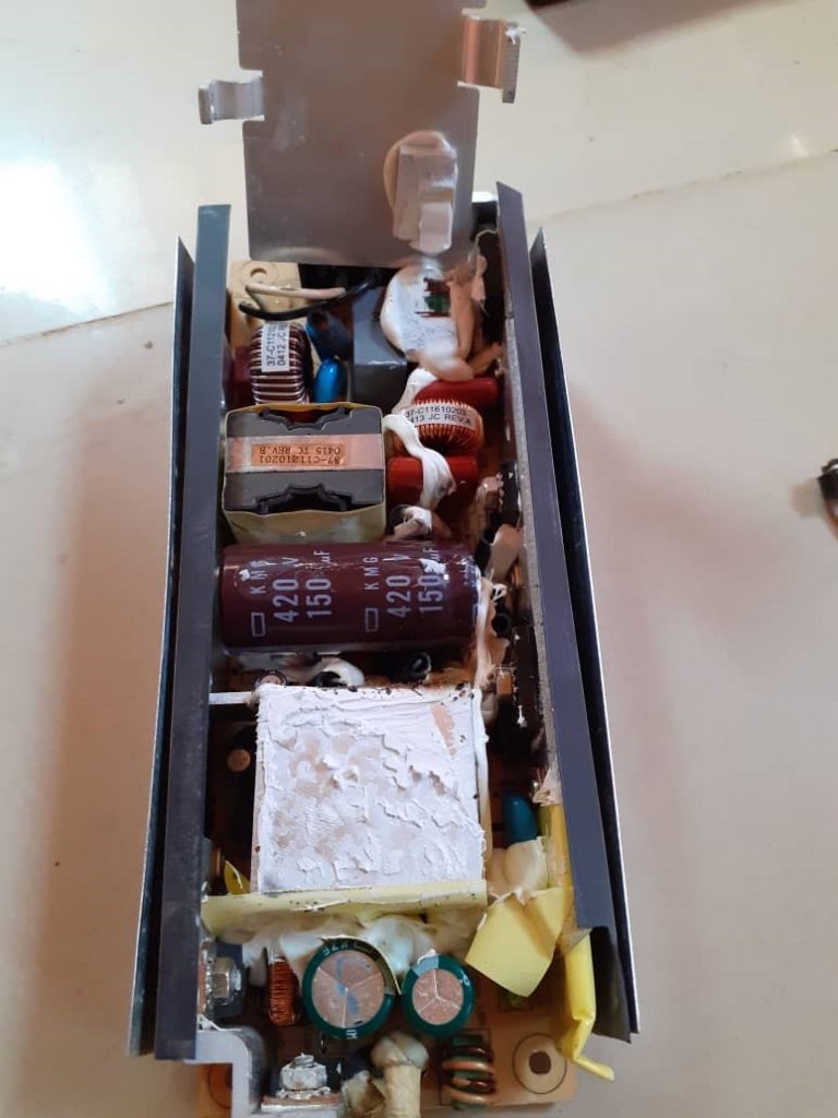
    The Power Supply: The power supply used in this project design was a switch mode power supply. The choice was due to its consistency in supply output the required voltage demanded from it at the specified current rating.

    smart infrared remote control gate system: power supply module
    The power supply used here outputs 5V, 4A

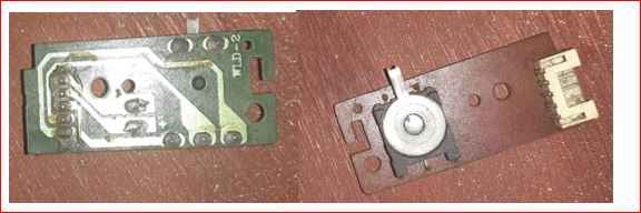
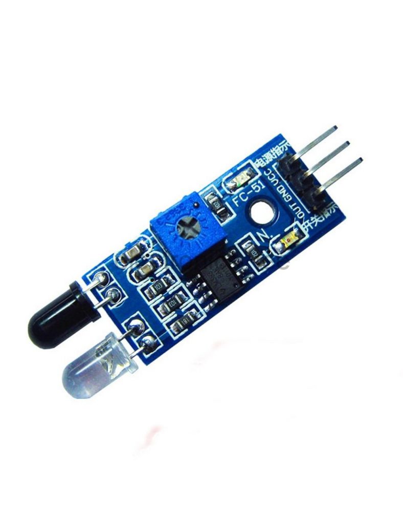
    Infrared Obstacle Avoidance Sensor Module: The infrared obstacle avoidance sensor is made up of two infrared LEDs. One is used as the transmitter, while the other is the encapsulated receiver. These two IR sensors are soldered on the same PCD board that has an adjustable potentiometer.

    smart infrared remote control gate system
    obstacle avoidance sensor

    The two sensor LEDs are controlled by an on-board comparator LM358 which compares the threshold between the inputs of the IR LEDs. The potentiometer used here was to adjust the sensitivity of the IR receiver. The IR obstacle avoidance sensor module works thus: The transmitter (usually the bright encapsulated LED) emits IR signal and once there is no obstacle in its path, the receiver doesn’t get to receive it. But if there is an obstacle in the transmitter’s line of sight, the signal bounces off the obstacle and echoes back to the receiver through diffraction and reflection. Once the receiver LED receives this signal, it activates the signal received active on-board LED to indicate that it has received the signal and it will automatically change the signal output on its  board (which is HIGH, giving 1) to LOW, producing 0).

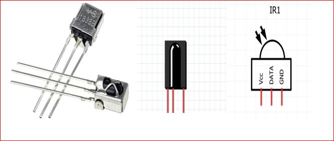
    IR Receiver TSOP1838:

    smart infrared remote control gate systemaremote gate opener project
    IR receiver 1838

    This IR receiver operates at 38KHz frequency and can decode the IR signals sent to it from the remote controller. The pinout diagram is shown above. The IR receiver, however, when tested with non-programmable chips, shows some inconsistent signal received due to its data pin. The IR receiver runs on a 5V power supply, hence there is no power conversion for it. It was simply plugged into the output of the power supply kit shown above, and we were ready to start receiving specific IR signals from the transmitter(the remote controller) at a 38KHz frequency.

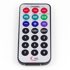
    IR transmitter (remote controller)

    This is a 21 button remote control that is universal. It is very versatile and often low cost as it was meant as a car Mp3 player’s control. The portability of this remote made it very ideal for our project. Hence we used two (2) specific buttons for our selection of opening and closing of the gate. The ‘CH-’ button does the opening of the gate while the ‘CH+’ does the closing of the gate. Of course this was only possible when the IR receiver has decoded the signal each button t transmits and the microcontroller matches the HEX code generated by such signal by the command it prompts

    smart infrared remote control gate system
    mp3 remote control (IR transmitter module)

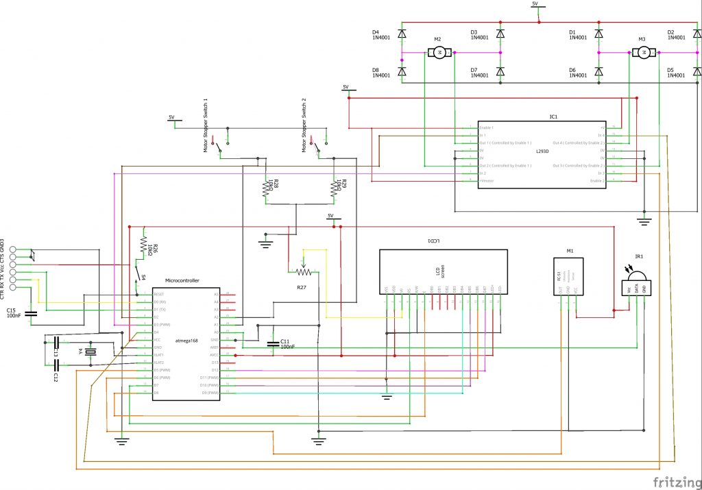
    The Complete Circuit Diagram

    smart infrared remote control gate system: the circuit diagram
    IR Remote Control Gate System Schematic

    The circuit diagram uses an Atmega168 microcontroller. The microcontroller is designed with a 16MHz crystal for its synchronous clocking speed. As shown in the circuit diagram. This is connected to pin 9 and pin 10 of the IC. This is marked XTAL1 and XTAL2. To aid with this and to suppress noise generated in the chip, we used a 22pF capacitor connected to the same pin, but to be used as a filter, they were connected with respect to the ground.

    To burn programs into the IC, we used the 6 male header pins for the connection of our FTDI cable. The FTDI programmer has 6 pins for programming: the CTR or chip reset, the receive pin, which is connected to the transmit pin of the microcontroller, the transmit pin Tx, which is connected to the receiver of the microcontroller, the Vcc power pin that is hooked to +5V and the Chip select that is grounded.

    In order to work with the microcontroller and rework with it, there was a need to add a manual reset button. And this is connected to the Active LOW pin (pin 1) of the microcontroller through a 10KΩ precision resistor. This is also called the pull-up resistor that keeps pin 1 of the MCU to see a 5V supply until the reset button is pushed.

    The microcontroller needs 100nF capacitors to be connected across its analog Vcc with respect to the ground. And the other connected from the reset pin to the FTDI pin.

    The LCD connection is done using the 4-bit method of data connection. No I2C modules or connections were needed since the output digital pins of the microcontroller were enough to communicate with the LCD module. The LCD is powered directly at pins 1, 2, 15, and 16 respectively without using a pull-up resistor for the LED+ backlight pin. The wiper of a 10KΩ pot is connected to the Vo pin of the LCD to adjust the screen contrast. The Register Select (RS) is connected to pin 7 and the Enable of the LCD is connected to pin 8. The 4 data pins are connected at pins 9 through 12 of the microcontroller.

    The obstacle avoidance sensor is powered by the 5V power supply while its output pins is connected to digital pin 6 of the microcontroller. This works on HIGH and LOW voltage reverences. Such that the microcontroller uses the HIGH voltage it outputs when it detects an obstacle in its line of sight to set a condition that would allow the gate not to close when it is open and a car is parked between the gates.

    The IR receiver is connected to the analog pin 0 which reads the output pin of the IR receiver for HEX code signals. If there is no response from the microcontroller when the user press remote control to the face of the receiver, this is probably because the output pin of the receiver has disconnected from the A0 pin of the MCU.

    The stopper switches, which were used to detect when the gate has closed or open worked on analog voltage values such that when they are powered from a 5V reference, and the action of the moving gate tray lodges or dislodge them from this supply; the microcontroller notices these changes and know when the gate is open or not.

    The motor driver controls the two DC motors that control the movement of the gate trays. According to the circuit diagram; we connected the inputs of the motor driver to the microcontroller, which in turn outputs a control mechanism depending on which side of the inputs we feed in HIGH and LOW voltages (which is equivalent to 5V and 0V reference). We use the diodes there to prevent reverse feedback mechanisms in terms of voltage back to the MCU or damage to the motor driver chip as a result of electromagnetic energy collapsing when the motor is being cut off from power.

    Programming the Microcontroller

    Theprogramming of the microcontroller was done using the Arduino IDE. We were able to use the FTDI cable to burn programs into the chip by using the inbuilt complier provided by the Arduino IDE. Below is the code for the project design.

    /* THE FOLLOWING PROGRAM CONTROLS THE OPENING AND CLOSING OF 
     *  A GATING SYSTEM SUING AN INFRARED TRANSMITTER CONTROL> 
     *  ALSO KNOWN AS REMOTE CONTROLLED GATE
     *  Courtesy of Smartech Labs.
     * 
     *///include lcd lib
     #include <LiquidCrystal.h>
    //include IR lib
    #include <IRremote.h>
    //declare the instance Lcd and state where the data pins 
    LiquidCrystal lcd(8, 7, 9, 10, 11, 12);
    
    //declare and state where you connected the IR input pin
    int RECV_PIN = A0;
    
    long gateWaitTime = 30;
    long timeCount;
    long previousMillis = 0;
    
    boolean obstacleRemove = false;
    
    //declare an instance to receive the IR signal
    IRrecv irrecv(RECV_PIN);
    //decode the IR signals 
    decode_results results;
    
    //declare the limit switches
    int swtch1, swtch2, swtch3, swtch4;
    
    //declare the motordiver inputs
    #define motor1Backward 2
    #define motor1Forward 3
    #define motor2Backward 4
    #define motor2Forward 5
    
    
    //declare and define the pin for IR proximity sensor pin
    int proxSensorPin;
    
    void setup()
    {
      //begin serial monitor to comm with MCU and PC
      Serial.begin(9600);
      //begin the lcd screen and state what type of lcd used
      lcd.begin(16, 20);
      // In case the interrupt driver crashes on setup, give a clue
      // to the user what's going on.
      Serial.println("Enabling IRin");
      // Start the receiver
      irrecv.enableIRIn(); 
      Serial.println("Enabled IRin");
    
      //state the I/O pins
      pinMode(swtch1, INPUT);
      pinMode(swtch2, INPUT);
      pinMode(swtch3, INPUT);
      pinMode(swtch4, INPUT);
    
      pinMode(motor1Forward, OUTPUT);
      pinMode(motor1Backward, OUTPUT);
      pinMode(motor2Forward, OUTPUT);
      pinMode(motor2Forward, OUTPUT);
    
      //Print a welcome note
      lcd.setCursor(0, 0);
      lcd.print("WELCOME SMARTECH");
       lcd.setCursor(0, 1);
      lcd.print("     LABS               ");
      delay(2000);
      lcd.setCursor(0, 0);
      lcd.print("REMOTE CONTROLED");
       lcd.setCursor(0, 1);
      lcd.print("  GATE SYSTEM      ");
        delay(2000);
        lcd.setCursor(0, 0);
      lcd.print("  GATE SYSTEM      ");
             lcd.setCursor(0, 1);
      lcd.print("   PROJECT     ");
          delay(2000);
         lcd.setCursor(0, 0);
      lcd.print("  GATE SYSTEM      ");
             lcd.setCursor(0, 1);
      lcd.print("   PROJECT     ");
           lcd.setCursor(0, 0);
      lcd.print("  PLS PRESS A        ");
             lcd.setCursor(0, 1);
      lcd.print(" REMOTE COMMAND     ");
    }
    
    
    void loop() {
      if (irrecv.decode(&results)) {
        Serial.println(results.value, HEX);
        // Receive the next value
        irrecv.resume(); 
      }
    
      proxSensorPin = digitalRead(6);
      swtch1 = analogRead(A1);
      swtch2 = analogRead(A2);
      swtch3 = analogRead(A3);
      swtch4 = analogRead(A4);
    
    Serial.println(proxSensorPin);
    Serial.print(swtch1);
    Serial.print(" ");
    Serial.print(swtch2);
    Serial.print(" ");
    Serial.print(swtch3);
    Serial.print(" ");
    Serial.println(swtch4);
    
     if((results.value == 0xFFA25D) && (proxSensorPin == HIGH)) {
      if((swtch2 >= 900) && (swtch3 >= 900)){
      lcd.clear();
          lcd.setCursor(0, 0);
      lcd.print("  GATE OPENING      ");
      lcd.setCursor(0, 1);
       for(int i = 0; i < 10; i++){
        lcd.print(".");
        delay(100);
        digitalWrite(motor1Backward, HIGH);
      digitalWrite(motor2Backward, HIGH);
      digitalWrite(motor1Forward, LOW);
      digitalWrite(motor2Forward, LOW);
      }
      }
           lcd.clear();
     lcd.setCursor(0, 1);
     lcd.print("  GATE OPEN          ");
      
    }
    
    
    if((results.value == 0xFFE21D) && (proxSensorPin == HIGH)){
      if((swtch2 <= 90) && (swtch3 <= 90)){
      lcd.clear();
             lcd.setCursor(0, 0);
      lcd.print("  GATE CLOSING       "); 
      lcd.setCursor(0, 1);
      for(int i = 0; i < 10; i++){
        lcd.print(".");
        delay(90);
        digitalWrite(motor1Backward, LOW);
      digitalWrite(motor2Backward, LOW);
      digitalWrite(motor1Forward, HIGH);
      digitalWrite(motor2Forward, HIGH);
      } 
      }
          lcd.clear();
     lcd.setCursor(0, 1);
     lcd.print("  GATE CLOSE         ");
    
    }
    
    
    if(results.value == 0xFFE21D) {
      if(obstacleRemove == false){
       if((swtch2 <= 90) && (swtch3 <= 90)&& (proxSensorPin == LOW)){
        lcd.clear();
        lcd.setCursor(0, 0);
     lcd.print("OBSTACLE AT GATE  ");
     lcd.setCursor(0, 1);
     lcd.print(" PLEASE REMOVE     ");
     
        
       }
    }
    }
    
    if(results.value == 0xFFA25D) {
       if((swtch2 >= 900) && (swtch3 >= 900)&& (proxSensorPin == LOW)){
        lcd.clear();
          lcd.setCursor(0, 0);
      lcd.print("  GATE OPENING      ");
      lcd.setCursor(0, 1);
       for(int i = 0; i < 10; i++){
        lcd.print(".");
        delay(100);
         digitalWrite(motor1Backward, HIGH);
      digitalWrite(motor2Backward, HIGH);
      digitalWrite(motor1Forward, LOW);
      digitalWrite(motor2Forward, LOW);
      }
      }
      lcd.clear();
     lcd.setCursor(0, 1);
     lcd.print("  GATE OPEN          ");
    }
    
     else if(results.value == 0xFFE21D){
       if((swtch2 <= 90) && (swtch3 <= 90)&& (proxSensorPin == HIGH)){
      obstacleRemove = true;
      if(obstacleRemove == true){
      lcd.clear();
             lcd.setCursor(0, 0);
      lcd.print("  GATE CLOSING       "); 
      lcd.setCursor(0, 1);
      for(int i = 0; i < 10; i++){
        lcd.print(".");
        delay(90);
        digitalWrite(motor1Backward, LOW);
      digitalWrite(motor2Backward, LOW);
      digitalWrite(motor1Forward, HIGH);
      digitalWrite(motor2Forward, HIGH);
      } 
      lcd.clear();
     lcd.setCursor(0, 1);
     lcd.print("  GATE CLOSE          ");
    } 
       }
       obstacleRemove = false;
     }


    if(timeCount - previousMillis == gateWaitTime) {
    if((swtch2 <= 90) && (swtch3 <= 90)&& (proxSensorPin == HIGH) ){
         lcd.setCursor(0, 0);
      lcd.print("  GATE CLOSING       "); 
      lcd.setCursor(0, 1);
      for(int i = 0; i < 10; i++){
        lcd.print(".");
        delay(100);
        digitalWrite(motor1Backward, LOW);
      digitalWrite(motor2Backward, LOW);
      digitalWrite(motor1Forward, HIGH);
      digitalWrite(motor2Forward, HIGH);
      } 
      lcd.clear();
     lcd.setCursor(0, 1);
     lcd.print("  GATE CLOSE          ");
    }  
    }
    timeCount= previousMillis;
    timeCount = millis()/1000;
    Serial.println(timeCount);
        delay(500);
    }
    

    Uploading the above syntax into the Arduino IDE, we would find the system working as expected. It should be noted that the HEX codes used for controlling gate movement differs in each remote controls (IR transmitter modules). To learn how to decode your own HEX code, check out our tutorials on that.

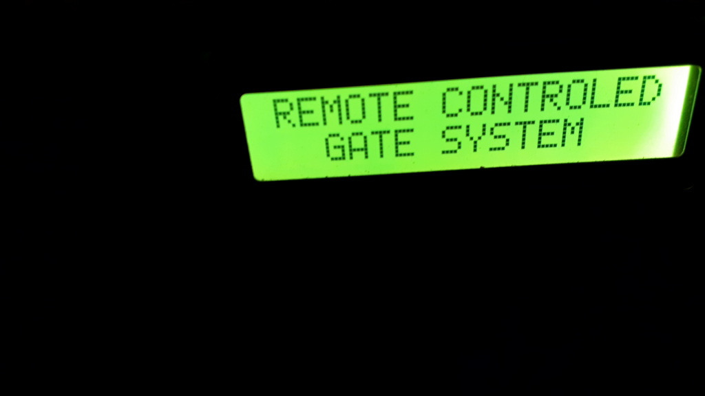
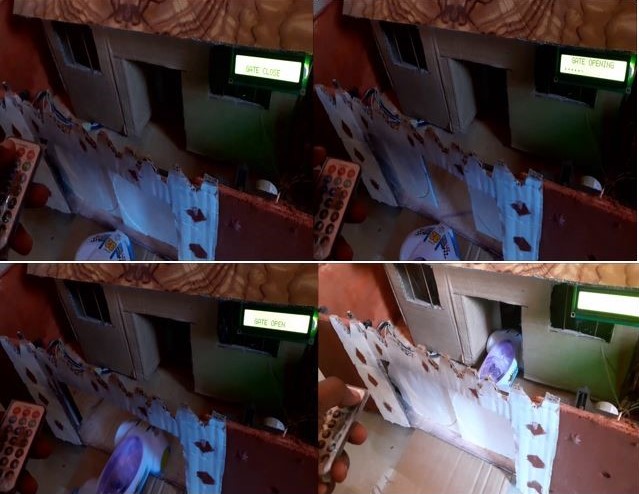
    The LCD would display a welcome message and show the title of the project, smart infrared remote control gate system.

    project result display
    LCD display project title

    To view the tutorial video, just click on the youtube clip below to watch

    Conclusion

    Building a Remote Gate Opener DIY system is one of those projects that looks technical but is actually fun and manageable. Once you install it, you’ll enjoy the comfort of opening your gate from your car, your porch, or even your bedroom.

    Not only does it add convenience, but it boosts security, adds value to your home, and gives you a sense of achievement — because you built it.

    So gather your tools, grab your components, and start creating your own smart automated gate system today.

    Read More

  • How to Install a Security Camera System: A Step-by-Step DIY Guide

    How to Install a Security Camera System: A Step-by-Step DIY Guide

    Tired of feeling vulnerable? Whether you’re protecting your home, your business, or your loved ones, a security camera system is one of the most effective deterrents against crime. But professional installation can be expensive, often costing hundreds of dollars on top of the equipment.

    The good news? Installing your own system is a very achievable DIY project. It requires patience and basic tools, but it doesn’t require an electrician’s license. This comprehensive, step-by-step guide is designed to walk you through the entire process—from planning your camera placements to setting up remote viewing on your phone. By the end, you’ll have a professional-grade security system that you installed yourself, giving you peace of mind and saving you money.

    A Quick Note on DVR vs. NVR Systems

    Before we dive in, it’s crucial to know what kind of system you have. You’ll encounter two main types:

    • DVR (Digital Video Recorder): Works with analog cameras. It uses RG59 coaxial cables to transmit video and a separate power cable. These are often more affordable but are generally considered legacy technology.
    • NVR (Network Video Recorder): Works with IP (Internet Protocol) cameras. It uses standard Ethernet cables (Cat5e/Cat6) to transmit video, audio, and power simultaneously (via Power over Ethernet, or PoE). NVR systems offer higher resolution, easier installation, and are the modern standard.

    This guide will cover the installation process for both systems, as the physical mounting and planning are very similar.

    Before You Start: Tools, Equipment & Safety

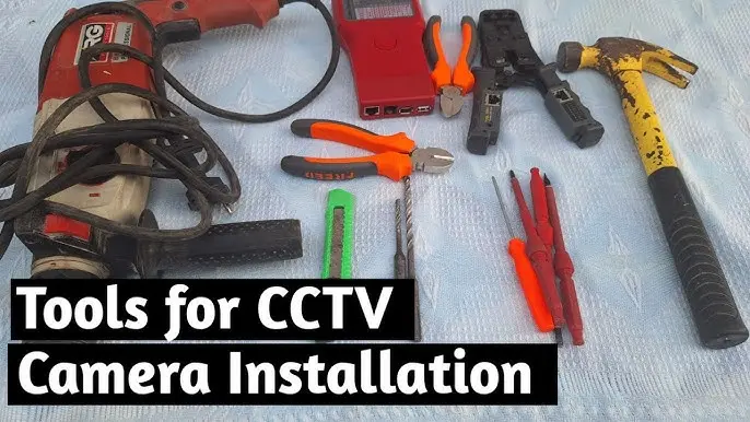
    tools needed for security camera system
    tools needed for security camera system

    A successful DIY project is all about preparation. Gathering the right tools and understanding safety precautions will make the entire process smoother and safer.

    Tools You’ll Need

    • Power Drill & Drill Bits (including masonry bits for brick/concrete)
    • Screwdrivers (Phillips and Flat-head)
    • Hammer
    • Ladder
    • Stud Finder (to avoid drilling into studs unnecessarily)
    • Cable Stripper/Crimper (Essential for NVR systems to terminate Ethernet cables)
    • Fish Tape (invaluable for running cables through walls and ceilings)
    • Pencil & Tape Measure
    • Level (to ensure your cameras are straight)
    • Safety Glasses & Work Gloves

    Choosing Your System: DVR vs. NVR

    If you haven’t purchased a system yet, here’s a quick comparison to guide your choice:

    FeatureDVR (Analog) SystemNVR (IP) System
    Camera TypeAnalog CamerasIP Cameras
    Cable UsedRG59 Siamese (Video + Power)Ethernet (Cat5e/Cat6)
    Video QualityGood to High (up to 4K)Excellent (often 4K and beyond)
    Power SupplySeparate power cable/boxPower over Ethernet (PoE) – single cable
    InstallationMore complex cable managementSimpler, single-cable runs
    FlexibilityLimited by cable lengthHighly flexible, can use network switches

    Our Recommendation: For most new installations, an NVR system with PoE is the best choice due to its simpler wiring, higher potential quality, and modern features.

    Step 1: Prep the Digital Recorder (DVR)

    Steps to Install CCTV Surveillance Cameras is a wiki guide that takes you directly to how to quickly install your CCTV surveillance cameras.

    Before we start off; it is very important you set up the DVR and turn it on. Connect your mouse and your DVR power jack to the 12V supply output of the 12V adapter. Connect the VGA cable from the DVR to the monitor or TV using an HDMI or VGA to AV converter. Allow it to boot, and watch its progress on a monitor or TV if you are using a VGA to AV converter. Read about how to install CCTV surveillance cameras with a remote viewing here to know about the full materials needed to get started.

    Step 2: Prep the Power Cable

    how to install CCTV surveillance cameras with a remote viewing
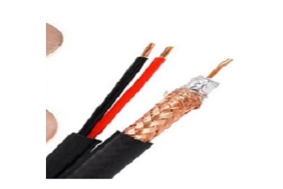
    RG59 coaxial cable with power at point of mounting camera

    Then, there is little or no need to make any change as regards to where the cameras would be positioned. Otherwise, it would be good to choose positions where the cams would be somewhat hidden and have little or no blind spot views. So, if given the option for a surface wiring, identify these positions.

    how to install CCTV surveillance cameras with a remote viewing
    Crimped out RG59 wires with power

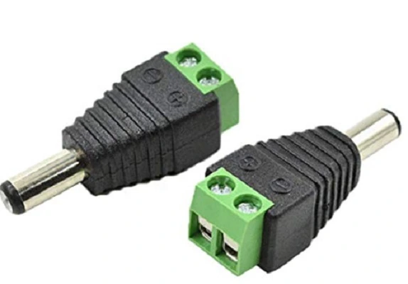
    Use a wire crimping tool and peel off the wires as shown in the picture above. This is useful to connect the 12V power to the CCTV male power plug. This is done in a way that the positive (usually red color) +12V wire is connected to the point marked (+) whereas the negative wire (black colored) is connected to the port marked (-).

    CCTV male power plug

    Step 3: Prep the RG59 Coaxial cable

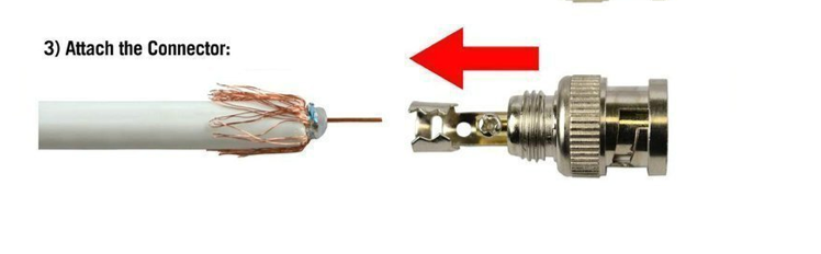
    open the BNC connector
    first move

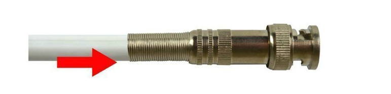
    Take the BNC connect and unscrew the female-female couple. Push the end of the cable into the F- connector so the connector tube goes between the foil and the outer housing of the cable.

    the next move
    next move

    push the end until the white insulator is flush with the bottom of the connector. Use anything to expose 1/8 inch of the braid and foil by pinching and pulling off a piece of the out jacket. DO NOT ALLOW ANY OF THE COPPER SHIELDING TO TOUCH THE CENTER OF THE CONDUCTOR

    the last move
    the last move

    Slide the crimp ring inside over the bottom of the connector and screw on tightly. Using a crimping tool, pinch pinch the shield to secure a strong housing. Test the cable using a Cable tester after this.

    Step 4: Prep the CCTV Cameras

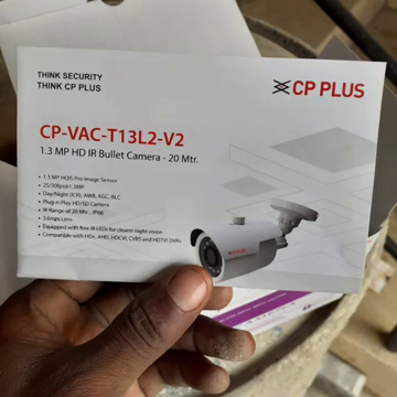
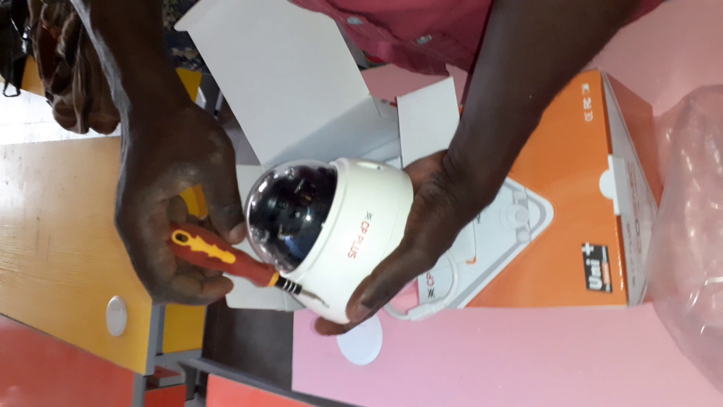
    After you are done with the RG59 wiring; bring out the cameras from their packs.

    how to install CCTV surveillance cameras with a remote viewing
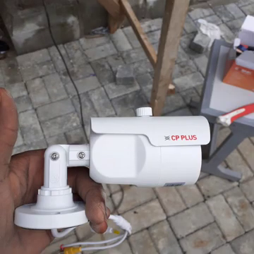
    We used CP plus for this tutorial.

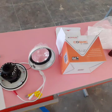
    This blog post used CCTV Bullet cameras from CP plus industries. You can read more about their specifications at their product web page.

    how to install CCTV surveillance cameras with a remote viewing
    A dome CCTV type camera
    Setting the CCTV Camera
    adjust the CCTV camera according to where you want

    It is important to note that surveillance cameras with higher megapixel(MP) ratings tend to have better image capture and streaming than the one with lower MP ratings. For example this tutorial was made with cameras with 1.3MP and 2MP resolution qualities.

    Alternatively, you have to choose cameras with Night vision attributes so that you can also watch your surveillance at night. And between HD720 and HD1080, always go for the latter.

    Smartech CCTV

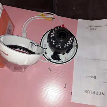
    Remove the cameras from their packs and begin to unscrew them carefully. If you are planning to survey the outside surroundings of the place you are installing the CCTV surveillance; it is recommended to use the Bullet (or turret) type of camera for the outdoors and the dome type for indoor surveillance.

    Smartech CCTV

    Each of the cameras comes with two plug and set connectors(other manufacturers might add a picture mode button, like in the case of CP Plus). This is where you would connect you BNC from your RG59 coaxial and your power.

    Smartech CCTV

    These cameras run on 12V and about 250mA-350mA current rating. Ensure you have a stable power supply unit for this or get a 16-channel power supply used to power CCTV cams. This is what we used for this how to install CCTV surveillance cameras with a remote viewing wiki.

    Step 5: Drill Holes For Wall Pegs

    Smartech CCTV
    dripping holes for mount pegs

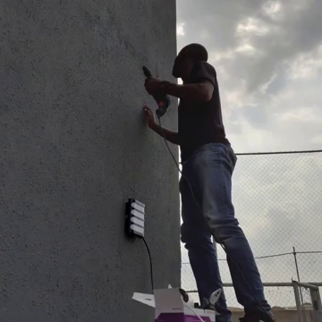
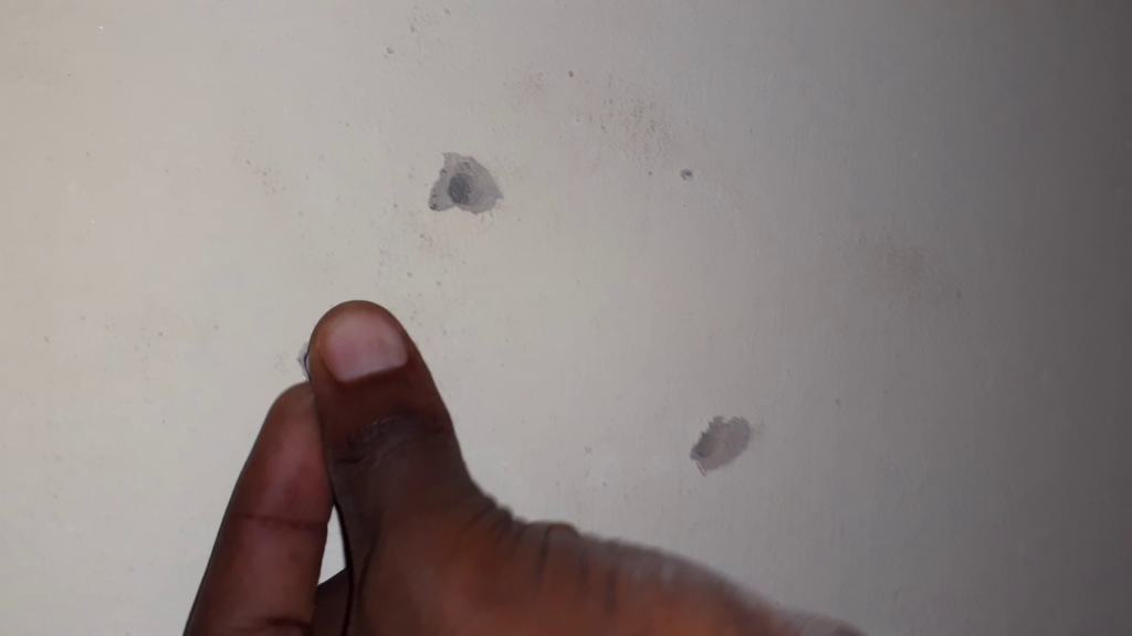
    Remove the mount (drill) template for any of the cameras you wish to install and mark out the positions to drill for your pegs. There is need to go to each spot and measure out the exact spot and take note of this. Using a drilling machine with a good torque. Make holes and insert the wall pegs into these holes. These would serve as fastening points for the CCTV cameras.

    how to install CCTV cameras
    put the pegs in the holes drilled

    Use your hand drill machine and drill these holes into the wall. Insert the pegs and then ensure that they are firm.

    how to install CCTV Cameras

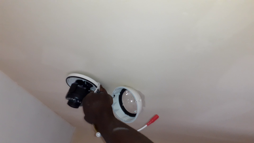
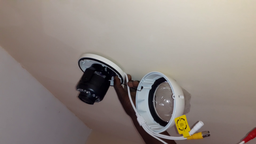
    Place the base of your camera and use the screw to hold it firm.

    Installing the Hard Disk (HDD) for Recording/Playback

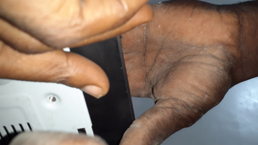
    Turn off the DVR for this process. And open the DVR by unscrewing the safety screws that held the cover.

    how to open a DVR set
    unscrew the screw holding the casing of the DVR
    Smartech CCTV
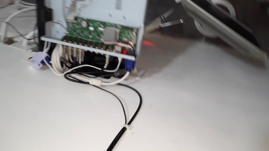
    The inside of the DVR

    Install the HDD by connecting the HDD connectors to its appropriate sockets and hold the HDD in place by screwing from below.

    Go back to your screen on the monitor and start the recording by right clicking on the mouse and selecting “start recording“.

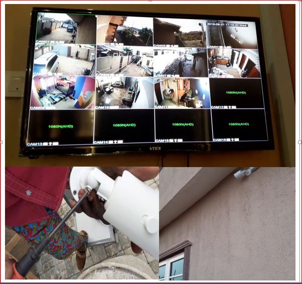
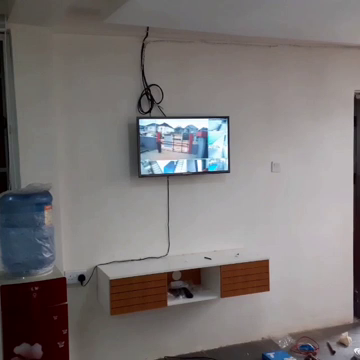
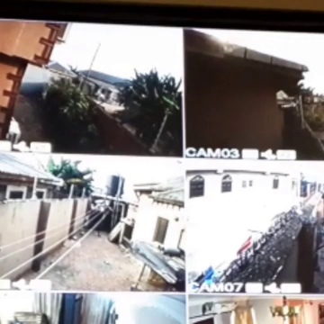
    You should see the channels of cams connected showing together. Select any one and display its full view. Now, we are done with our Steps to Install CCTV Surveillance Cameras.

    how to install CCTV surveillance cameras with a remote viewing
    how to install CCTV surveillance cameras with a remote viewing
    The various cameras showing in their chambers

    Conclusion

    This guide explains how to install CCTV surveillance cameras. If you used this method to successfully implement remote surveillance for your home or workplace security monitoring, please let us know in the comment area. You can contact us on WhatsApp, Twitter, Telegram, Instagram to and send us pictures or ask questions too.

    The slide YouTube vide

    Read More

  • Final Year Project Ideas for Engineering Students (Hardware, Software, IoT & Automation)

    Final Year Project Ideas for Engineering Students (Hardware, Software, IoT & Automation)

    So, it’s finally here—your final year project. Exciting, right? But also a little scary. Picking the right idea can feel like standing in front of a huge buffet and not knowing what to choose. You want a project that is unique, practical, and something that doesn’t make you lose sleep at night.

    Don’t worry. You’re about to discover a list of smart, creative, and industry-relevant final year project ideas across hardware, software, IoT, and automation. These ideas aren’t just for passing grades—they’re portfolio boosters that can help you stand out.

    Let’s dive in.

    Who This Guide Is For

    This guide was created for engineering students in the following fields:

    ✔ Electrical Engineering Students

    Projects related to circuits, power systems, embedded systems, automation, and control.

    ✔ Electronics / Elect-Elect Engineering Students

    Microcontrollers, PCB design, IoT systems, sensor projects, embedded hardware, etc.

    ✔ Mechanical Engineering Students

    Mechanical design, renewable energy systems, fabrication projects, automation mechanisms.

    ✔ Computer Engineering Students

    AI/ML models, embedded systems, security systems, cloud computing, IoT applications.

    ✔ Software Engineering Students

    Web development, mobile apps, backend systems, AI models, data science projects.

    ✔ Mechatronics & Automation Engineering Students

    Robotics, PLC/SCADA, machine control, intelligent systems, industrial automation.

    If you fall into any of these categories, you will find curated project ideas specifically suited to your field.

    How to Choose the Best Final-Year Project

    Choosing a strong final-year project goes beyond selecting a trending topic. Below are key criteria to guide you:

    1. Choose a Project Aligned With Your Interest

    Pick something you genuinely enjoy. This makes research and implementation easier.

    2. Evaluate Your Budget

    Some projects require expensive components like sensors, motors, or software licenses. Confirm affordability before committing.

    3. Consider Your Skill Level

    Beginner-friendly? Intermediate? Advanced?
    Choose one that challenges you, but is still doable within your timeline.

    4. Check Availability of Materials

    Make sure all tools, components, and software are locally available or can be shipped easily.

    5. Supervisor Requirements

    Some supervisors prefer practical hardware. Others prefer simulation or software-based projects. Keep this in mind to avoid revisions.

    6. Timeline & Complexity

    A semester-long project should be realistic. Choose an idea with a clear scope.

    7. Documentation Potential

    Your project must be easy to document with diagrams, results, code snippets, and experimental data.

    Essential Tools & Technologies You Should Know

    Many engineering projects revolve around core tools and technologies. Understanding these increases your success:

    Microcontrollers

    • Arduino
    • ESP8266 / ESP32
    • PIC / Atmega328P
    • Raspberry Pi

    Programming Languages

    • Python
    • C/C++
    • JavaScript
    • MATLAB
    • Java
    • Kotlin

    Software Tools

    • Proteus
    • MATLAB/Simulink
    • AutoCAD
    • Fusion360
    • SolidWorks
    • Fritzing
    • VS Code

    Sensors & Modules

    • DHT11/DHT22
    • PIR sensor
    • Gas sensor
    • Ultrasonic sensor
    • Soil moisture sensor
    • Relay modules
    • Motor drivers

    Networking & IoT

    • Blynk
    • MQTT
    • Firebase
    • ThingsBoard

    Having these skills gives you an advantage when selecting complex project ideas.

    These projects require programming knowledge and involve microcontrollers, sensors, or embedded systems. They are great for Electrical, Electronics, Mechatronics, and Computer Engineering.

    1. IoT-Based Smart Home Automation Using ESP32

    Difficulty: Intermediate
    Control home appliances using WiFi, relay modules, and a mobile app (Blynk or MQTT).

    2. Smart Hydroponics System Using Arduino

    Difficulty: Intermediate
    Automates plant growth using pH sensors, moisture sensors, pumps, and LCD display.

    3. Smart Energy Meter with Load Monitoring

    Difficulty: Advanced
    A prepaid or postpaid system that monitors power consumption in real time.

    4. Smart Helmet for Safety with GPS & Accident Detection

    Uses accelerometers, GPS, GSM modules to alert family or emergency units in case of accidents.

    5. Solar Tracker System Using LDR Sensors

    Automatically aligns solar panels to maximize efficiency.

    6. RFID-Based Door Lock System

    Combines RFID tags and solenoid door lock for security applications.

    7. IoT Water LevelMonitoring System

    Monitors water levels in tanks and sends updates to a mobile dashboard.

    8. Voice-Controlled Home Automation (Google Assistant)

    Integrates Google Assistant + NodeMCU + relays.

    9. Smart Flood Alert System

    Uses water sensors and GSM modules to send alerts.

    10. Automated Irrigation System

    Uses soil sensors and relays to control water pumps automatically.

    More Programmable Project Ideas

    1. Design and development of soil moisture sensor using Arduino.
    2. Design and development of burglar alarm system using Arduino and PIR sensor- with SMS alarm using GSM module.
    3. Design and construction of CO2, CO, and other dangerous gases detector for home.
    4. Design and construction of temperature measurement and regulator system for home, hospital rooms, farmhouse and poultry farms.
    5. Design and development of temperature measurement system using Arduino with visual display.
    6. Design and development of hospital patient call system.
    7. Design and development of electrocardiogram system for hospitals.
    8. Design and development of baby noise monitoring system.
    9. Design and construction of proximity infrared detector for security purposes.
    10. Design and development of aquarium temperature probe system for temperature monitoring and water level indicator.

    🔧 Non-Programmable / Hardware Project Ideas

    These projects focus more on electrical circuits, renewable energy, and mechanical systems. They are ideal for Electrical, Mechanical, or Power Engineering students.

    1. Mini Hydropower Generator

    Build a working water turbine system that generates electricity.

    2. Automatic Power Changeover Switch

    Switches power from grid to generator/inverter automatically.

    3. Design & Construction of a DC to AC Power Inverter

    A pure sine wave or modified sine wave inverter.

    4. Wind Turbine System (Small Scale)

    Mechanical + electrical integration project.

    5. Automatic Street Light Control Using LDR

    Street light turns on and off based on ambient light.

    6. Car Anti-Theft System (Hardware-based)

    Circuit that immobilizes a car engine when tampered with.

    7. Fire Alarm System Using Smoke Sensors

    Simple hardware project with buzzer and smoke detection.

    8. Solar-Powered Mobile Phone Charger

    Low-cost renewable energy project.

    9. Battery Level Indicator Using LED Array

    Educational hardware project.

    10. GSM-Based Security Alarm

    Uses GSM module to send alerts during intrusion.

    More Non-programmable, Hardware Final-Year Project Ideas for Engineering Students

    1. Design and development of television (tv) transmitter using I.C. components.
    2. Design and construction of smoke detector alarm system against fire hazards.
    3. Design and constrution of compact egg candler for poultry farms to know if the eggs are viable or not.
    4. Design and construction of temperature regulator system for poultry farm.
    5. Design and construction of hearing aid (small sound amplifier).
    6. Design and construction of stun gun device.
    7. Design and development of security light alarm system for home security.
    8. Design and construction of an Automatic Roller-mixer/centrifuging system for laboratory specimens with timer mechanisms.
    9. Design and construction of a Wireless power transfer system using LEDs.
    10. Design and construction of an automatic blender control system with a Timer selector.

    💻 Software Development Final-Year Project Ideas

    These projects are perfect for Software Engineering, Computer Science, and IT students. They require coding skills, UI/UX, and backend knowledge.


    1. Hospital Management System (Web App)

    A full-stack application for patient records, billing, staff management, and appointment scheduling.

    2. E-Commerce Mobile App

    Includes product listing, payment integration, order management, and analytics.

    3. AI-Based Fake News Detection System

    Uses machine learning models to classify news articles as real or fake.

    4. Smart Attendance System Using Face Recognition

    Uses Python and OpenCV for face recognition-based attendance.

    5. Chatbot for Customer Support

    AI-based NLP chatbot for websites and apps.

    6. Weather Forecasting System Using Machine Learning

    Predicts weather patterns using data science techniques.

    7. Student Result Management System

    Stores scores, calculates CGPA/GPA, and generates reports.

    8. Food Delivery App Clone (Like Jumia or Uber Eats)

    Full UI/UX and backend implementation.

    9. Mobile Banking App Simulation

    Handles transactions, balance inquiry, and user management.

    10. Crime Reporting & Tracking System

    Helps users report crimes and track police responses.

    More Software Development Final-Year Project Ideas

    1. Android location alarm project
    2. GPS Based Human Tracking project
    3. Student Examination Datacard project
    4. Student Attendance System by Barcode Scan
    5. Student Attendance System With QR Scan
    6. Hotel Reservation Android
    7. Smart Health Consulting Project
    8. Farming Assistance Web Service
    9. Corporate Dashboard Project
    10. Mobile(location based) Advertisement System
    11. Smart Health consulting system
    12. Wireless Data Handling And Management
    13. Android Anti-Virus Application
    14. E-Learning Platform using Cloud Computing
    15. University/College Social Networking Web Project

    🤖 Automation & Machine Control Final-Year Project Ideas

    Ideal for Mechatronics, Control Engineering, and Industrial Automation students.

    1. Automated Sorting Machine Using Sensors

    Sorts objects based on color, weight, or size.

    2. PLC-Based Conveyor Belt Control System

    Demonstrates automation found in industries.

    3. Robotic Arm Control Using Joystick

    Builds understanding of servo motors, kinematics, and control.

    4. Automatic Bottle Filling Machine

    Automation project using sensors, relays, and conveyor belts.

    5. Automatic Car Parking System

    Parking space detection using ultrasonic sensors.

    6. Obstacle-Avoiding Robot

    Uses ultrasonic sensors to navigate around objects.

    7. Fire-Fighting Robot

    Automated robot that senses fire and sprays water.

    8. Intelligent Traffic Light Control System

    Adaptive control based on traffic density.

    9. Motor Speed Control System (PID Control)

    A classic control engineering project.

    10. Smart Factory Simulation

    A model demonstrating Industry 4.0 automation.

    Project Ideas for Engineering Students

    1. Single-Phase Motor Control System
    2. Two-Phase Motor Control System
    3. Three-Phase Motor Control System
    4. Industrial Cruser Control System
    5. Industrial Mixer Control System
    6. Industrial Control Panel
    7. Industrial Vibrator Control System
    8. Industrial Coolant Control System
    9. Industrial Plantain Peeler Control System
    10. Industrial Ice-cream Mixer Control System

    By the way, if you feel like a total novice (P.S. we won’t tell, fingers crossed), and you want to know more about everything you need to know about projects, see here: final-year project; all you need to know. We also have a store where you can purchase the required components and tools for these projects and a team ready to consult for you all through your project journey. . Visit our online store and experience a world of solutions to your project concerns. Here are the more than 250+ Final-Year Project Ideas for Engineering Students you came for below in the PDF link below:

    Automation and Machine Controls Final-Year

    Final Year Project Ideas for Engineering Students

    Click here to download the .docx format or PDF format of the project list.

    Bonus Section: High-Scoring Project Ideas That Impress Supervisors

    These projects demonstrate creativity, engineering depth, and real-world relevance:

    • Renewable energy mini-grid systems
    • Smart agricultural solutions
    • IoT-based safety and security systems
    • Embedded automation prototypes
    • Machine learning models with practical use-cases
    • Robotics projects
    • Energy-efficient systems
    • Industrial automation demos

    Projects in these categories often lead to excellent grades and external opportunities.

    Conclusion

    Selecting a final-year project doesn’t have to be stressful. With over 50 carefully curated project ideas across haYour final year project is your chance to shine. Pick something you enjoy, something meaningful, and something that speaks to your engineering passion. Whether you choose hardware, software, IoT, or automation, make sure the project reflects your best abilities.

    At the end of the day, your project should tell a story—your story as an engineer.

    Please note that you can always contact us with your own project topic for consultation and technical assistance. We will be very glad to help you the best we we can. Let us know if you have any further questions in the comment section. You can also drop a suggestion too! To join the conversation, join our Telegram community.

    FAQs

    1. What is the easiest final-year project for engineering students?

    Basic hardware projects like automatic street lights, battery level indicators, or simple web apps are easiest for beginners.

    2. What is the most popular final-year engineering project?

    Currently, IoT-based automation systems and AI projects are the most in demand.

    3. How do I know if my project idea is good?

    A good project should be:

    • Practical
    • Documentable
    • Affordable
    • Innovative
    • Achievable within the given period

    4. Can I use Arduino for my final-year project?

    Yes! Arduino-based projects are very popular and supervisor-friendly.

    5. How long should my final-year project take?

    Most projects take 8–16 weeks depending on complexity and available tools.

    6. Can two or more students work on one project?

    Yes, teamwork is allowed as long as responsibilities are clearly documented.

  • Final Year Project: All You Need to Know

    Final Year Project: All You Need to Know

    Stepping into your final year project feels a bit like riding a roller coaster—exciting one minute, exhausting the next. You get the highs, the lows, and sometimes those “why did I choose this?” moments. But guess what? It doesn’t have to drain you or leave you discouraged. That’s exactly why we put this guide together.

    Welcome to Final Year Project: All You Need to Know—your friendly roadmap through the chaos! Stick around till the end, because we’re about to walk you through how to choose the right project and everything else you should know before diving in. Let’s do this! 🚀

    Factors to Consider When Choosing a Final Year Project: all you need to know

    Doing a project takes more than getting yourself a nice project topic and implementing it. It demands functionality, relevance, knowing its cost requirement, feasibility, and lastly approval. We will now be visiting each of these requirements individually for deeper understanding.

    Project Functionality

    Final Year Project: all you need to know
    functionality ladder climb

    Here you’re required to ask the question, “what purpose does my project serve?!” It’s ok whatever the number of purposes it may serve. The more the merrier as the saying goes. Similar questions like:

    • “what problem does this project solve?!”
    • Or “what does this project offer to its user?!”
    • How will it work?
    • Does it have practical applications?

    Knowing the answers to these questions tend to help you crack down on the root of its functionality, these questions would make sure you dig out the usefulness of your project leaving nothing buried. In some cases, you discover an unrealized/ unpopular problem that makes things more interesting, because you may just be onto something.

    For example, a smart irrigation system should automate water delivery based on soil moisture. The functionality should be well-defined and measurable.

    Project Relevance

    Final Year Project: all you need to know
    What is the relevance of your project?

    The word relevance implies the connectedness and applicability of your chosen project to your department. Considering how wide this section could be, we have decided to break it into two subsections to achieve our desired result in giving you the knowledge you need to get your project hitting the ground running. These are:

    Departmental relevance:

    Relevance certificate Final Year Project: all you need to know
    The type of award to be earned

    As an Engineering student, your are not expected to pick up a project primarily about fishery and vice versa. Whatever topic you’re holding has to be related, if not entirely (because most life applications involve practices from various departments), but majorly to your department or area of specialization. To make this more practicable, take for instance; as an electrical engineering student, you need to answer the question, “how much of the composition of this project relies on electricity and wiring?!” The greater the percentage of the project’s composition that’s related to your course, the closer you are to a perfect topic.

    Societal relevance:

    Problem solving
    Problem solving attribute

    Here you’re required to answer the question, “how applicable is this project in your locality”, as a matter of fact, the most applicable projects are the ones that solve local problems/ issues. This is where I tell you to look around and always keep your eyes peeled and ears open, because, most times it’s not difficult to find out.

    Having said that. In some cases, not all projects offer an exact or direct societal relevance. So, it’s ok to just meet up with the departmental relevance criteria alone and move on. This is summarized in most science, technology, and engineering student as SDG-based (sustainable development goal) projects. You can read more here.

    Project Cost

    Project cost
    what is your project cost compared to your budget?

    This Is one of the simplest and yet most important of all the key points listed here. It is paramount to do a market research or estimated-cost of how much it would take to pull off such a project you have chosen to embark on.

    Depending on the faculty, discipline and project topic of choice, the cost involved may be less or high. Generally, the project topic determines what the cost range would be.

    For science, technology and engineering student or group of students; there is an extra mark awarded for people who are actually designing, building, and construction of physical projects. However, for science, technology and engineering student  embarking on building physical projects . Once you’ve gotten your topic, you’ll be set with a little walk around any equipped hardware store near you and the internet; to assemble your gadgets to get started. You can look up one of such stores is the Smartech online store. They make it easier for you to get the prices for your project parts/components and tools. They also offer some free services with regards to that. They can send the components to you, we are national, help you test and ensure the components or modules are working, assisting you with code snippets etc. Read the full post here. Buy from us here.

    Project Feasibility

    feasiblity of your project topic
    how feasible is your project topic?

    This might sound familiar and If you are thinking realization, then Yes!! You need to know how realisable your project selection is before embarking on it, and a few of the factors mentioned in this article help to account for that, so, rest easy we’ve got you. It’s one thing to get the perfect topic, and it’s another thing to be able to implement it, or develop it. While you have a project with a relevant functionality, the cost requirement may just be too high for your pocket (and that’s up to you really, how much is worth passing out in flying colors?!). Then in another scenario, you may have the perfect project with doable costs, but, “do you have the knowledge base for it?!” Most projects due to their nature and aim at innovation tend to demand a large/fairly strange amount of knowledge, and when we say knowledge, it also includes your skill in handling tools and equipment.

    This right here is what makes Smartech A. T. store a favourite, we don’t just sell components and equipments to you, but we also work with you on how to practically use those components. We are well aware that in most cases, it’s either the school has insufficient equipments and tools to go round, for those that sell components; not every one you need may be available or you just don’t get the right amount of attention from your project supervisor. These shouldn’t be the conditions discouraging you from doing the project you want. The team at Smartech A.T. ltd work towards satisfying these conditions for you, so, don’t get discouraged, reach out today if this is you.
    Project Approval

    Final Year Project: all you need to know
    Approval badge

    Of course we can never talk about a final year project without talking about your supervisor. You would always need your supervisors “go ahead” to start a project. We bet it will interest you to know that in some cases the supervisors do suggest project topics for you, please consider them(it), if that happens to you, many times, they are topics that your supervisor is already vast in and can easily offer precise guide on. However, if that’s not your case, putting this article to work already eases the burden for you, does it not?!  And approval is just within your grasp. Knowing what to look for always makes the search period shorter. This is the last stage a project will pass through before implementation starts.

    Possible Pitfalls to Avoid When Choosing a Project Topic

    pitfalls to avoid
    pitfalls to avoid
    • Catchy project topics means cost intensive project topics: This tries to buttress on the choice of project topics to embark on. To choose a project that is is resonating loud would mean to be packing a fat wallet to finish it. In the years of experience we have had, most Machine Learning (ML), Deep learning, etc. Some of the projects are something that are not within undergrad students. Yes, the supervisor may always propose these topics to the student but it is advice you do a project topc consultation to know if you can afford to take on the cost of the project topic. We recommend you go for project topic you are good at, that won’t cut deep inside your pocket and which you can always get out of
    • Know the total turnaround time for project defense: Most students will have very little time on their hands before the defense and would wait until it is very late before they can commence proper. Some projects take longer time than the others, you have to do some testing, record your observations etc.  When you have done the needful, this would be a landside for you.

    avoid these pitfalls
    avoid these pitfalls
    • Know Your Prowess: The whole idea is to get you acquainted with a particular project topic. At the end of the project work, you are expected to be an expert in that particular work. Knowing where your prowess lies and how fast and easy you could wrap your head around a topic ou found interesting would also motivate you to keep pushing the project even when times gets rough along the way.

    Getting Help: What We Can Do For You

    Virtual Team

    smartech as a team
    Have a team

    We are a tech start and doing various research in tech and engineering fields is part of what we do. We have consulted for many undergrad students masters students and PhD professors with regards to their project and thesis works. You can see some of  the google reviews here. We are always available to take enquiries and offer consultancy services for anyone who wishes to embark on this journey. The following are the benefits of working with us.

    smartech services offer

    Final Year Project Topic Consultancy

    This allows us to critically look at the project topics of choice and offer practical working guidelines to make it better. We exhaust the scope of the project from a feasible and realistic viewpoint; letting you know what is achievable, doable, and what isn’t. You know what to expect with your budget plan. Your project topic: All you need to know about the project topic and how to make the best of it summarized in a comprehensive forum where the center of attraction is you. Questions like, how long would it take you to complete? Everything for a token.  Armed with these pointers, you can plan yourself better when embarking on your final year project work. To learn more about this, follow this link.

    Online Sales and Services for Final Year Project Kits/Modules

    components sold on our online store

    Smartech’s online store does more than just sell components, modules, and tools for use in science and engineering. They have tech guys who are on standby to take your questions and guide you on how to make best of what you bought from them. Since they are not only an online store, but also makers who have used the products and found the best ways to use it.

    Project Consultancy

    Smartech offer this services in the following ways

    A step-by-step guide to getting you started with the project work/thesis

    Offering custom teaching on how to solve the challenges encountered with project work/thesis weather remotely or in-person.

    Building custom parts and designs ranging for PCB boards, prototypes, 3D print shapes etc.

    Conclusion

    You can go though all of our videos on YouTube channel or read more on the blog post for some of the free tutorial post. We would like to hear from you regarding what you think. Leave us a comment below and you can reach us on any of our handles below.

    Frequently Asked Questions on Google Search for Final Year Project Research:

    Choosing a Topic:

    • What are some good final year project topics for [my field of study]?
      • Answer: This is very dependent on your specific field. You can refine your search by adding specific keywords like “sustainable,” “machine learning,” “AI,” or your thesis area. Utilize university resources like faculty recommendations, project databases, and past thesis archives.
    • How do I choose a project topic that aligns with my interests and skills?
      • Answer: Reflect on your passions within your field. Do you enjoy research, design, fieldwork, or problem-solving? Identify your existing skills in software, hardware, analysis, or data interpretation. Match your interests and skills to potential project areas.
    • What are some unique and original project ideas?
      • Answer: Look for gaps in existing research, emerging technologies, or local/community challenges. Consider combining different disciplines or applying established methods to new areas. Brainstorm with peers, professors, or industry professionals for fresh perspectives.

    Research and Methodology:

    • Where can I find relevant research materials for my project?
      • Answer: Utilize scientific databases like JSTOR, ERIC, and Google Scholar. Check your university library resources, online repositories, and conference proceedings. Consult with your thesis advisor for field-specific journals and publications.
    • What are the different research methods I can use for my project?
      • Answer: The suitable method depends on your project type. Options include surveys, interviews, experiments, simulations, case studies, data analysis, and theoretical modeling. Discuss your options with your advisor and ensure your chosen method aligns with your resources and timeframe.
    • How do I create a strong research question and hypothesis?
      • Answer: Your question should be specific, focused, and researchable. It should identify a gap in knowledge and lead to a clear hypothesis, a tentative answer you aim to prove or disprove. Consult your advisor and refine your question until it’s well-defined and achievable.

    Project Implementation and Completion:

    • What are the key steps for managing my project effectively?
      • Answer: Develop a timeline with milestones, set realistic deadlines, and track your progress regularly. Utilize project management tools, organize your data and research materials, and communicate effectively with your advisor and collaborators.
    • How do I overcome challenges and setbacks during my project?
      • Answer: Be prepared for unexpected issues. Adjust your timeline if needed, seek help from your advisor or mentors, and consider alternative approaches. Maintain flexibility and resilience to navigate hurdles effectively.
    • How can I make my final presentation impactful and engaging?
      • Answer: Tailor your presentation to your audience. Use clear visuals, concise language, and highlight your key findings. Practice your delivery, answer questions confidently, and showcase your passion for your research.

    General Concerns:

    • How do I ensure my project is original and avoids plagiarism?
      • Answer: Properly cite all sources, paraphrase effectively, and document your research process diligently. Utilize plagiarism checkers and discuss referencing style with your advisor.
    • What are some resources available to support my final year project?
      • Answer: Utilize university writing centers, research labs, library workshops, and academic mentors. Consider funding opportunities, grants, or industry collaborations for additional support.
    • What are the expectations for a successful final year project?
      • Answer: Demonstrate thorough research, strong methodology, critical analysis, and clear conclusions. Present your findings confidently, showcase your skills, and highlight the significance of your project to your field.

    Remember, the final year project is a stepping stone into your professional future. Approach it with diligence, passion, and a willingness to learn. This research is a valuable opportunity to showcase your potential and set yourself apart as a capable and knowledgeable graduate.

  • Voltage Sensor Module: Measure Solar Panel Voltage level

    Voltage Sensor Module: Measure Solar Panel Voltage level

    Hello dear reader , in this tutorial we will be talking about using the Voltage Sensor Module to Measure Solar panel voltage level. The Voltage Sensor Module is a voltage sensing module that can be interfaced with an Arduino for measuring DC voltages within 2V – 25V. To read more about the technical details, go to shop.

    Understanding how to accurately measure the voltage level of a solar panel is essential in solar power system design, testing and troubleshooting. One of the simplest and most reliable ways to achieve this is by interfacing a solar panel with an Arduino using a voltage sensor module. This project allows you to observe voltage behavior under different sunlight conditions, compare daytime output fluctuations, and protect your electronics by ensuring incoming voltage stays within safe tolerances. What makes this project especially valuable is that it provides real-time visual and serial feedback of your solar input, making it ideal for students, DIY beginners, and renewable energy enthusiasts who want to learn instrumentation and energy monitoring.

    voltage sensor module
    The voltage sensor

    Components Used for Project Tutorial:

    In this practical, we will be using the Following Component.

    All these components can be bought on our online store. Alternatively, if you can’t find them, leave us a message on WhatsApp or Telegram group for assistance or in the comment section way down below.

    To complete this tutorial, the primary items used include the solar panel serving as the energy source, an Arduino microcontroller functioning as the measurement and processing unit, and the voltage sensor module acting as the interface that allows the panel’s output to be safely read without overloading the Arduino pins. Supporting elements include wires, a breadboard to simplify and organize connections, and a laptop running the Arduino IDE for code uploading and serial monitoring. The components are selected specifically because they are easy to assemble, safe to operate, affordable, reusable across multiple projects, and effective in demonstrating basic principles of solar measurement systems.

    Arduino Voltage Sensor Module: The Principle of Operation

    Arduino Voltage sensor module pinout

    The Voltage sensors are made up of  the following input pinouts (VCC and GND) socket – (which can take in Maximum Voltage of 25v). These pinouts are used for measuring the voltage. On the other side, it has 3 pins which contains (VCC, GND and S where S is the Analog pin that can be connected to Arduino).

    The Arduino voltage sensor module works by taking a higher input voltage and reducing it to a lower scaled value that the Arduino can safely interpret. Internally, the module uses a voltage divider network consisting of precision resistors that proportionally lower the input voltage level based on a fixed ratio. This scaled-down voltage is then fed into one of Arduino’s analog input pins, where it is converted into a digital numerical value by the ADC (Analog-to-Digital Converter). Once the microcontroller receives this reading, software logic reconstructs the original voltage mathematically using the known scale factor of the module. The fundamental idea is that instead of directly connecting the solar panel to the Arduino, the voltage sensor provides safe isolation, monitoring accuracy, and ensures that even fluctuating sunlight peaks do not damage the board.

    The internal circuit of the voltage sensor

    The Arduino Sensor Module contains 2 Resistors 30kΩ and 7.5kΩ that uses the principle voltage divider rule. This is given in the Equation as:

    voltage sensor module equation

    Read up more on this this link. Let us proceed to how to hook this up to an Arduino Uno board and use it to measure DC voltage from a Solar panel up to 24V DC.

    Voltage Sensor Module: Measure Solar Panel Voltage level
    A typical solar panel used in this project

    Solar Panels and How They are Made

    Solar panels use photovoltaic cells, or PV cells, which are made using silicon crystalline wafers similar to the wafers used to make computer processors. The silicon wafers can be either polycrystalline or monocrystalline and are produced using several different manufacturing methods. The most efficient type is monocrystalline (mono) which are manufactured using the well known Czochralski process. This process is more energy-intensive compared to polycrystalline (poly) and therefore more expensive to produce.

    Polycrystalline wafers, on the other hand, are slightly less efficient and are made using several purification processes followed by a simpler, lower cost, casting method. More recently, cast monocrystalline or cast mono cells have been gaining popularity. The reason is due to the lower-cost casting process used to make cast mono cells which is similar to the process used for polycrystalline silicon cells. However, cast-mono wafers are not quite as efficient and pure mono wafers made using the Czochralski process. The various types are namely:

    • Monocrystalline silicon cells – Highest efficiency and highest cost
    • Cast monocrystalline cells – High efficiency and lower cost
    • Polycrystalline silicon cells – Lower efficiency and lowest cost
    Arduino Voltage Sensor Module Measure Solar Panel Voltage level
    The solar panel breakdown part

    Read all about solar panels and how they are manaufactured here. However, for this tutorial our focus is to use Arduino Voltage Sensor Module to Measure Solar Panel Voltage level .

    Voltage Sensor Module: Measure Solar Panel Voltage level

    The Circuit Diagram

    Voltage Sensor Module: Measure Solar Panel Voltage level
    Circuit Diagram for the connection

    To use the Arduino Voltage Sensor Module with Arduino Uno board, the 3 pins of the Voltage sensors are connected to Arduino Uno as shown above. In which, the VCC is connected to 5V. The GND is also connected to the GND of the Arduino. The “S” which is the Analog pins slot is connected to the Analog part on the Arduino board, which could be connected to (A0, A1, A2, A3 and …). For this project we used the A1 analog pin on the Arduino Uno board. To read the battery level for a 3V battery, the above circuit was used.

    The voltage sensor module connects to the solar panel output terminals so that the varying DC voltage created by sunlight can be monitored and analyzed. As sunlight increases, the solar panel generates higher voltage, which the sensor module scales down and sends into the Arduino for processing. The Arduino then analyzes the incoming analog signals and converts them into readable voltage values. This allows the real-time voltage level of the solar panel to be displayed through the serial monitor or an LCD if added. What makes this arrangement significantly useful is that it allows safe measurement without requiring complex test instruments. It also allows you to observe performance characteristics, such as stability, peak voltage, and response under shading. The voltage sensor module therefore acts as an intermediary bridge that simplifies the relationship between renewable energy hardware and the microcontroller software environment.

    Voltage Sensor Module: Measure Solar Panel Voltage Level(Arduino Sketch)

    Measuring the real-time voltage output of a solar panel using an Arduino and a voltage sensor module requires a stable code routine that continuously reads analog values, converts them precisely, and then reports them in volts. The role of the Arduino sketch here is not only to fetch values from the sensor, but also to interpret them, scale them accurately to match the sensor’s voltage divider ratio, and display them in a meaningful way—whether on the Serial Monitor, an LCD module, or transmitted wirelessly to a monitoring dashboard.

    The sensor module typically provides the Arduino with a fraction of the actual solar voltage because the voltage divider inside the module reduces the incoming level into the safe analog-reading range. In the sketch, this divider must be accounted for in the calculation. This is where the calibration constant becomes extremely important. The Arduino receives raw ADC values (0-1023 on most boards), and the sketch interprets these readings against the module’s reduction factor. Without these calculations, the values would appear meaningless and inconsistent, especially when used under variable sunlight conditions.

    In the code, the setup stage prepares the serial communication and initializes the pin used for reading. The loop stage continuously reads, processes, and prints updated voltage data. Some Arduino sketches include minor averaging techniques that stabilize noise that normally appears when sunlight fluctuates due to clouds or shading. A well-structured sketch compensates for this by applying a steady conversion ratio and returning real-time output without sudden spikes.

    It is also possible inside the sketch to define an operational threshold, meaning the system can detect when the solar panel voltage falls below a specified A-level. This allows the Arduino to trigger external relays, alarms, or even automate a switching mechanism that protects batteries from under-voltage. The sketch can therefore serve not only as a data-monitoring tool but as a smart energy-management routine.

    In a more advanced form, the measurement sketch can be extended into a data-logging system where voltage readings are stored with timestamps. From this point the same code can be merged with SD-card modules, IoT dashboards, or Wi-Fi upload functions that track solar performance throughout the day. The fundamental structure remains the same, but the sketch becomes more powerful by giving actionable insight into energy production trends.

    So, the Arduino sketch serves as the interpreter between the voltage sensor module and meaningful human understanding. By transforming electrical values into readable voltage levels, the code makes the system usable by engineers, installers, and students who want a clear view of how their solar panel behaves across varying loads, temperatures and irradiance conditions.

    Explanation of Source Code (Arduino Sketch)

    float PVr1 = 30000.0;
    float PVr2 = 7500.0;
    float batteryVoltSensor, vinBattery;
    const int voltagePinBattery = A0;
    
    void setup() {
      Serial.begin(9600);
       Serial.println("Now in Setup");
    Serial.println("Now exiting Setup function");
    }
    
    void loop(){ 
    Serial.println("Now in loop function");
    
      //now doing calculations
      batteryVoltSensor = analogRead(voltagePinBattery);
     batteryVoltSensor = (batteryVoltSensor * 5.0)/1023.0;
     vinBattery = batteryVoltSensor/(PVr2/(PVr1+PVr2));
    
    Serial.println(vinBattery);
    
    Serial.println("Now exiting loop function");
     delay(1000);
    }
    

    The Arduino sketch is the same as the sketch used for measuring the various battery level voltages. You can take a look at it here. The sketch begins with declaring and assigning floating point variables that takes care of the values of resistors used to form the voltage divider rule. Other variables were declared to later compute the voltage of the PV (solar panel) measured. In the setup() function, the serial communication is began at a baud ate of 9600 bits per second, we printed out some dummy string text to know when we have entered the setup() function and have exited out of it.
    In the loop() function, we carried out the calculation that measured the PV voltage. This was done using the analog pin where the Analog pinout of the Arduino voltage sensor was connected. Then this was multiplied by 5V since the Arduino Development board can take a maximum of 5V of logic voltage. Converted to to actual voltage when divided by 1023 for 16 bits microcontrollers.

    The Arduino sketch programmed for this tutorial continuously samples the analog input pin where the voltage sensor module is attached. Through a mathematical relationship built into the code, the microcontroller converts the raw ADC value into a corresponding real-world voltage reading based on the module’s predetermined division ratio. The code keeps running and updating this value several times per second, allowing the user to observe even slight fluctuations caused by passing clouds or different solar orientations. The sketch also ensures that conversion accuracy is maintained through calibration factors written directly into the script, which refine measurement precision. The final computed voltage is then printed out through the serial monitor of the Arduino IDE, making observation effortless during indoor testing or outdoor data collection sessions.

    Results

    Once powered and connected outdoors, the results show a direct correlation between sunlight intensity and the voltage reported by the Arduino. Voltage values rise during strong sunlight, remain moderate under partial cloud cover, and decline toward evening. Early morning readings appear low and gradually increase as the sun moves to a higher angle. These observations confirm the sensitivity of the panel and the reliability of the voltage sensor circuit in tracking real-time energy production shifts.

    Voltage Sensor Module: Measure Solar Panel Voltage level
    Serial monitor result
    Voltage sensor Module: measure solar panel voltage level
    The final connection

    Explanation of Circuit Diagram

    The circuit diagram for this 21V PV panel uses the same source code (Arduino Sketch) given above. The voltage level of the solar panel for this Arduino Voltage sensor module measure Solar panel voltage level project was observed to increase by up to 22V and it was printed out on a serial monitor.

    The circuit diagram portrays how the solar panel terminals are linked to the voltage sensor input channel, while the module output pin is wired to Arduino’s analog port. Ground reference is consistently shared between the Arduino and the voltage module to stabilize signal flow. The purpose of the diagram is to visually clarify the electrical interaction between the solar generator and the microcontroller system. The layout prioritizes safety by ensuring the solar panel never connects directly to the Arduino analog pins, as that would exceed voltage tolerance. The diagram therefore provides the necessary guidance that ensures the connection style is correct, reliable, and electrically secure.

    Conclusion

    The serial monitor printing shows that we can measure or take the reading of various DC voltage levels of any solar panel that is within the range of 25V MAXIMUM using this voltage sensor. To take measurements above 25V, you have to see our other project tutorial. The readings obtained in this project would then be uploaded to a cloud dashboard using an Arduino Uno and an ESP8266-01 WiFi module.

    So what do you think about this tutorial? Can you reproduce this? or make further modifications to it? Let us know if you tried it and how it built you in the comment section below.
    Thank you.

    Measuring the voltage level of a solar panel using a voltage sensor module and Arduino is more than just observing a fluctuating reading on a screen—it is a powerful process that helps you understand how effectively your panel is converting sunlight into usable electrical output. With a properly calibrated sensor module and a well-structured Arduino sketch, you can monitor daytime variations, detect efficiency drops, troubleshoot irregular charging cycles, and verify panel health in real-world conditions. Whether the goal is experimentation, academic research, or practical solar system maintenance, the process equips you with the insight needed to design better, safer, and more reliable renewable-energy projects.

    As your familiarity grows, the same setup can evolve into automated protections, remote-monitoring systems, and long-term data analytics, turning a simple measurement into valuable engineering intelligence

    Frequently Asked Questions (FAQs)

    1. Can an Arduino measure a solar panel voltage directly without a sensor module?
    No, the Arduino cannot measure high voltage directly. Solar panels often produce voltages far above the Arduino’s safe ADC input limit. The sensor module steps that voltage down safely before measurement.

    2. Why does the sensor reading fluctuate during the day?
    Solar voltage naturally varies with sunlight intensity, shading, panel temperature, angle, and load demand. The fluctuations are normal and reflect real operating conditions.

    3. Does the voltage sensor module measure current as well?
    No, the voltage sensor module measures only voltage. To measure current, you need a current sensor such as ACS712 or a dedicated shunt-based measurement module.

    4. How accurate is the Arduino voltage reading?
    Accuracy depends on module calibration, reference voltage stability, wiring quality, ADC noise, and calculation precision inside the code. It improves significantly with calibration.

    5. Can this setup be used with larger wattage solar panels?
    Yes, as long as the measured voltage remains within the maximum sensor input rating. Higher wattage does not affect measurement safety—voltage does.

    6. Can the measured voltage be displayed on an LCD instead of the serial monitor?
    Yes, the sketch can be modified to display readings on LCD, OLED, Nextion, or even wirelessly on IoT dashboards without changing the measurement principle.

  • Arduino Voltage Sensor Module: Measure Battery  Level Voltage

    Arduino Voltage Sensor Module: Measure Battery Level Voltage

    Hello dear reader , in this tutorial we will be talking about the Arduino Voltage Sensor Module: Measure Battery Level Voltage with. The Arduino Voltage Sensor Module is a voltage sensing module that can be interfaced with an Arduino for measuring DC voltages within 2V – 25V. To read more about the technical details, go to shop.

    The voltage sensor

    Components Used for Project Tutorial:

    In this practical, we will be using the Following Component.

    All these components can be bought on our online store. Alternatively, if you can’t find them, leave us a message on WhatsApp or Telegram group for assistance or in the comment section way down below.

    Arduino Voltage Sensor Module: The Principle of Operation

    Arduino Voltage sensor module pinout

    The Voltage sensors are made up of  the following input pinouts (VCC and GND) socket – (which can take in Maximum Voltage of 25v). These pinouts are used for measuring the voltage. On the other side, it has 3 pins which contains (VCC, GND and S where S is the Analog pin that can be connected to Arduino).

    The internal circuit of the voltage sensor

    The Arduino Sensor Module contains 2 Resistors 30kΩ and 7.5kΩ that uses the principle voltage divider rule. This is given in the Equation as:

    Read up more on this this link. Let us proceed to how to hook this up to an Arduino Uno board and use it to measure DC voltage, rechargeable battery and Solar panel up to 24V DC.

    Arduino Voltage Sensor Module Measure battery voltage level

    The Circuit Diagram for 3V Battery Measurement

    Arduino Voltage Sensor Module Measure 3V battery voltage level
    3V Battery measurement

    To use the Arduino Voltage Sensor Module with Arduino Uno board, the 3 pins of the Voltage sensors are connected to Arduino Uno as shown above. In which, the VCC is connected to 5V. The GND is also connected to the GND of the Arduino. The “S” which is the Analog pins slot is connected to the Analog part on the Arduino board, which could be connected to (A0, A1, A2, A3 and …). For this project we used the A1 analog pin on the Arduino Uno board. To read the battery level for a 3V battery, the above circuit was used.

    The Source Code (Arduino Sketch)

    float PVr1 = 30000.0;
    float PVr2 = 7500.0;
    float batteryVoltSensor, vinBattery;
    const int voltagePinBattery = A0;
    
    void setup() {
      Serial.begin(9600);
       dht.begin();
    Serial.println("Now in Setup");
    Serial.println("Now exiting Setup function");
    }
    
    void loop(){ 
    Serial.println("Now in loop function");
    
      //now doing calculations
      batteryVoltSensor = analogRead(voltagePinBattery);
     batteryVoltSensor = (batteryVoltSensor * 5.0)/1023.0;
     vinBattery = batteryVoltSensor/(PVr2/(PVr1+PVr2));
    
    Serial.println(vinBattery);
    
    Serial.println("Now exiting loop function");
     delay(1000);
    }
    

    Results

    Digital Multimeter and Serial monitor Comparism
    Digital Multimeter and Serial monitor comparism

    The Circuit Diagram for 5V Battery Measurement

    Arduino Voltage Sensor Module: Measure Battery  Level Voltage
    5V Battery measurement

    The Source Code (Arduino Sketch)

    float PVr1 = 30000.0;
    float PVr2 = 7500.0;
    float batteryVoltSensor, vinBattery;
    const int voltagePinBattery = A0;
    
    void setup() {
      Serial.begin(9600);
       dht.begin();
    Serial.println("Now in Setup");
    Serial.println("Now exiting Setup function");
    }
    
    void loop(){ 
    Serial.println("Now in loop function");
    
      //now doing calculations
      batteryVoltSensor = analogRead(voltagePinBattery);
     batteryVoltSensor = (batteryVoltSensor * 5.0)/1023.0;
     vinBattery = batteryVoltSensor/(PVr2/(PVr1+PVr2));
    
    Serial.println(vinBattery);
    
    Serial.println("Now exiting loop function");
     delay(1000);
    }
    

    Results for 5V Battery Level on Arduino Voltage Sensor Module: Measure Battery Level Voltage

    Digital Multimeter and Serial monitor comparism
    Digital Multimeter and Serial monitor comparism

    The Circuit Diagram for 9V Battery Measurement

    Arduino Voltage Sensor Module: Measure Battery  Level Voltage
    Measuring 9V battery level

    The Source Code (Arduino Sketch)

    float PVr1 = 30000.0;
    float PVr2 = 7500.0;
    float batteryVoltSensor, vinBattery;
    const int voltagePinBattery = A0;
    
    void setup() {
      Serial.begin(9600);
       dht.begin();
    Serial.println("Now in Setup");
    Serial.println("Now exiting Setup function");
    }
    
    void loop(){ 
    Serial.println("Now in loop function");
    
      //now doing calculations
      batteryVoltSensor = analogRead(voltagePinBattery);
     batteryVoltSensor = (batteryVoltSensor * 5.0)/1023.0;
     vinBattery = batteryVoltSensor/(PVr2/(PVr1+PVr2));
    
    Serial.println(vinBattery);
    
    Serial.println("Now exiting loop function");
     delay(1000);
    }
    

    Results for 9V Battery Level on Arduino Voltage Sensor Module: Measure Battery Level Voltage Project

    9V Battery Measurement on serial monitor
    Serial Monitor Print

    The Circuit Diagram for 12V Battery Measurement

    Arduino Voltage Sensor Module: Measure Battery  Level Voltage
    12V Battery Level Measurement

    The Source Code (Arduino Sketch)

    float PVr1 = 30000.0;
    float PVr2 = 7500.0;
    float batteryVoltSensor, vinBattery;
    const int voltagePinBattery = A0;
    
    void setup() {
      Serial.begin(9600);
       dht.begin();
    Serial.println("Now in Setup");
    Serial.println("Now exiting Setup function");
    }
    
    void loop(){ 
    Serial.println("Now in loop function");
    
      //now doing calculations
      batteryVoltSensor = analogRead(voltagePinBattery);
     batteryVoltSensor = (batteryVoltSensor * 5.0)/1023.0;
     vinBattery = batteryVoltSensor/(PVr2/(PVr1+PVr2));
    
    Serial.println(vinBattery);
    
    Serial.println("Now exiting loop function");
     delay(1000);
    }
    

    Results

    The Circuit Diagram for 24V Battery Measurement

    Arduino Voltage Sensor Module: Measure Battery  Level Voltage
    The circuit diagram for 24V connection

    The Arduino Sketch

    float PVr1 = 30000.0;
    float PVr2 = 7500.0;
    float batteryVoltSensor, vinBattery;
    const int voltagePinBattery = A0;
    
    void setup() {
      Serial.begin(9600);
       dht.begin();
    Serial.println("Now in Setup");
    Serial.println("Now exiting Setup function");
    }
    
    void loop(){ 
    Serial.println("Now in loop function");
    
      //now doing calculations
      batteryVoltSensor = analogRead(voltagePinBattery);
     batteryVoltSensor = (batteryVoltSensor * 5.0)/1023.0;
     vinBattery = batteryVoltSensor/(PVr2/(PVr1+PVr2));
    
    Serial.println(vinBattery);
    
    Serial.println("Now exiting loop function");
     delay(1000);
    }


    Result for 24V Battery Level on Arduino Voltage Sensor Module: Measure Battery Level Voltage Project

    24V Battery measuremen
    24V Battery measurement

    Explanation of Circuit Diagram

    The circuit diagram for 3.3V, 5V, 9V, 12V and 24V uses the same source code (Arduino Sketch) given below. The battery level can be increased from 3.3V to 24V. and connected as shown above. Once this was done, connect the Arduino Uno board to the Personal Computer (PC), power up the Arduino IDE and copy the sketch given below.

    Conclusion

    The serial monitor printing show that we can measure or take the reading of various DC voltage levels of batteries ranging from 3V to 24V via the Analog pins on the Arduino, using the Serial Monitor on the Arduino IDE.

    So what do you think about this tutorial? Can you reproduce this? or make further modifications to it? Let us know if you tired it and built you in the comment section below.
    Thank you.

  • Automatic and Remote Control Pedestal fan Arduino (smart fan)

    Automatic and Remote Control Pedestal fan Arduino (smart fan)

    Hello everyone. In today’s project tutorial, Automatic and Remote Control Pedestal Fan Arduino (smart fan), we will be answering the following questions.

    Have you ever wondered if you could turn your home-standing fan into a smart fan? 

    Do you want to be able to control your pedestal fan using a remote control? perhaps add a  display screen?

    Do you want to see the temperature of your room displayed on this fan? Or perhaps you want to use the room temperature to control the speed of the fan?

    Won’t it be awesome to reverse engineer your pedestal fan and build an automatic and remote control pedestal fan Arduino (smart fan) that would use the room temperature in the room to automatically control the speed of the fan and then lets you control the fan speed at your own will with just any remote control lying around?

    Well, it is very possible and we will do this project tutorial today. Well stay tuned and ensure you read to the end because in this tutorial: we will be discussing how to achieve all of these functionalities inside the automatic control fan. But first, a brief introduction.

    What is a Pedestal Fan?

    A typical pedestal fan
    A typical pedestal fan

    This is an electric and oscillating fan supported by an adjustable, detachable stand with its head above the surface and is adjustable. The sole function of this is to circulate cool breeze around our room. The downside of this electrically powered fan is that its speed regulator control is manually operated.

    What Is Home Automation?

    Home automation is a step toward what is referred to as the “Internet of Things,” it is fun to build and easy if you have the right tools. Home automation is an aspect of IoT called domotics. There are a plenty variety of home automation systems that are available out there and these are equipped with making one’s life easier and more comfortable. Some popular home automation systems include:

    -A home security system that is responsible for monitoring your home and will send out alerts if there is an issue, like a broken window or a theft

    -An energy management system also helps in saving money spent on energy consumption by simply turning off the devices when they are not in use and adjusting the temperature regulators like thermostats.

     -A home entertainment system that can allow one to control his/her home’s lighting, music, and television from any location. These and so many others.

    However, for this project tutorials, our focus is the use a traditional standing fan, a temperature sensor, an Arduino board (standalone version), a TV remote, and other modules to build a smart fan that can measure accurately the temperature of the room, control the speed of the fan in “Auto Mode” using this temperature ranges while offering the user the choice to still override this using a TV remote control to set their own fan speed. Enough said already; let’s dive into designing the project.

    Components parts for Automatic and Remote Control Pedestal fan Arduino (smart fan)

    • Power Supply rated 5V, ≥ 2A or you can build your own here
    • Atmeg328p-pu microcontroller
    • 16MHz crystal oscillator (Newark part number 16C8140)
    • 10nF capacitors
    • A 10kΩ pull-up resistor
    • A reset push button.
    • Dallas temperature sensor DS18B20, maxim part number, 1534C4:
    • A 4.7KΩ pull-up resistor
    • Infrared receiver TSOP1738
    • IR remote controller or any old TV remote(that’s an IR Transmitter)
    • 560Ω 5-band resistor
    • 1µF ceramic capacitor
    • Generic jumper wires: male and female type.
    • 16 × 2 Liquid Crystal Display
    • 10KΩ potentiometer (trimmer)
    • 56OΩ precision resistor
    • LCD connector wires’
    • Header pins
    • 5V 4-channel Relay Module
    • A standing fan

    What is an Infrared (IR) Signal and an IR Receiver Module?

    Infrared radiation that produces Infrared signals or radiations (IR) are actually beams of light, it is that portion of the electromagnetic spectrum that extends from the long wavelength, or red, end of the visible-light range to the microwave range. Invisible to the eye, it can be detected as a sensation of warmth on the skin. Most of the radiation emitted by a moderately heated surface is infrared; it forms a continuous spectrum. Molecular excitation also produces copious infrared radiation but in a discrete spectrum of lines or bands. Everything which produce heat, emits infrared like our human body. Infrared have the same properties as visible light, like it can be focused, reflected and polarized like visible light. IR devices are those photonic components that contains semiconductor materials that are sensitive to IR radiations. They are divided into IR transmitter Light Emitting Diode (LED) and IR Receivers.

    Automatic and Remote Control Pedestal fan Arduino (smart fan)
    Infrared (IR) Remote controller and IR signals

    IR receiver is a sensor that is responsible for capturing the IR signal sent out by the IR emitter or in the case of this project the home TV remote. This exact part used here is shown in the component list to be the common TSOP1638.  It has 3 pinout configuration and can be used either with a programmable device or non-programmable device. In this Automatic and Remote Control Pedestal fan Arduino (smart fan) project, it is used with a programmable microcontroller Atmega328P chip.

    Configuring the IR Receiver Using Arduino.

    The IR Receiver TSOP1738 pinout

    This component as earlier mentioned, is the famous infrared receiver TSOP1738 that has three terminals with the Pin 3 connected to the HIGH of the PSU (+5 Vcc) supply and the Pin 2 connected to the ground terminal(or LOW) of the PSU while the Pin 1 is the output pin. It is called the data pin (or terminal) Do. To stop  the sensor (TSOP1738) from sending fluctuation signals to the MCU due to IR impulses from random sources, a very low capacitive capacitor is connected from the data pin to the ground. This is between 100nF to 33µF. This is shown below.

    Automatic and Remote Control Pedestal fan Arduino (smart fan)
    TSOP1738 Connection to the Arduino Standalone MCU

    Decoding HEX Value Codes From the IR Receiver on Automatic and Remote Control Pedestal fan Arduino (smart fan) project.

    Since this project isn’t based on a non-programmable Remote Control Home Appliance, there is a need to show the IR signals received by the Arduino on the serial monitor. The connection is shown above and the components are assembled on a breadboard.

    A Brief Explanation Of Hex Codes.

    The Decimal number system is also known as Base 10, since it’s comprised of ten numerals (symbolized by 0 through 9). Although we can only represent up to the number 9 by a single decimal digit, it’s possible to reference up to ten items by using zero ( 0) as an index to refer to the first ( 1st) item; thus, the numeral 9 would refer to the tenth ( 10th) item. With two digits we can refer to 100 items (zero through 99). In terms of the number of digits, 10 n (where n is the number of digits) equals the maximum number of items we can refer to. Therefore, the decimal equivalent of the largest binary number we can represent in 6 bits ( 111111 ) can be found as the sum of the first six powers of 2; starting with 2 to the power of zero (2 ^0): 20 + 21 + 2 2 + 23 + 24 + 25 = 1 + 2 + 4 + 8 + 16 + 32 = 63.

    Or, by simply using the formula: 2n – 1 = 64 – 1 = 63.

    To convert any binary number to hexadecimal, that is, base 16, simply order the bits into as many four-bit groups as possible, from the least significant position to the most significant position with any remaining group of only 3, 2, or 1 bits at the far left. Then convert each group to a single hex digit of 0 through 9 or A through F . So, to convert our 6-bit number of 111111 (63 decimal) to hex, we simply group the bits as: 111111 which is easily converted to: 3F hex. An 8-bit or 1-byte hexadecimal number can contain a maximum value of 255 decimal. A 10-bit binary number cannot exceed: 11 11111111 or 3FF  or 1023 decimal. But, the maximum number of Cylinders we can reference in 10 bits is 1024, since we begin counting from zero.

    A 32-bit unsigned integer value can be from 0 to 2(32-1). That is, from 0 to 2147483647.  Similarly, 64-bit unsigned integer value can be from 0 to 2(64-1). Now, 32-bit hex value can be from 0 to 0x7f f f f f f f There will be only 8 digits i.e. 7 f f f f f f f because 1 digit corresponds to 4 bit. Hence 8 digits correspond to 8×4 = 32 bits. So, this means the digits which are followed by 0x are hexadecimal. There are two important aspects to the beauty of using Hexadecimal with computers: First, it can represent 16-bit words in only four Hex digits, or 8-bit bytes in just two.

    Program Code to Decode the IR Signals off the Remote Controller

    //include the IR remote library
    #include <IRremote.h>
    //state the IR input to the MCU
    #define RECV_PIN A1
    //make it recognised to IR Lib
    IRrecv irrecv(RECV_PIN);
    //ask it it get results and save it
    decode_results results;
    
    void setup() {
     //enable the IR
      irrecv.enableIRIn();
    }
    
    void loop(){
    if(irrecv.decode(&results))  {
         irrecv.resume();
        //print the remote results in HEX codes
         Serial.println(results.value, HEX);
      }
    
    HEX Code values for Automatic and Remote Control Pedestal fan Arduino (smart fan)
    HEX Code values displayed on Serial Monitor on the Arduino IDE

    Wit the above program we can use the HEX code of each button to do a certain function on the speed control of the Alternating Current (AC) fan. These HEX value codes would be assigned in the program function later.

    Reverse Engineering The AC Fan Control.

    Fan disassembled
    The fan head

    Steps to Reverse Engineeer Pedestal fan to Automatic and Remote Control Pedestal fan Arduino (smart fan):

    Step 1:

    Remove the fan blade cover. As shown above. The type of AC fa then used in this project has to be opened from the front side.

    Step 2:

    Remove the Fan blades and the locate the screws holding the speed regulator back casing.

    Step 3:

    Unscrew the screws holding the control head cover.

    Step 4:

    The speed regulator knob of pedestal fan
    The fan speed regulator knob

    Remove the regulator knob and the back cover to locate the AC fan coil and the regulator panel. This is the only thing we want to mess with. The speed control knob has 4 input wires going into the coil of the . These are the speed 1 wire, the speed 2 wire, the speed 3 wire, and the neutral wire. These wires are to be connected to a relay module to allow automatic switching between each user button select to the appropriate coil connection terminal.

    labelling the wires properlly
    extend the wires and label them properly

    The Circuit Diagram for Automatic and Remote Control Pedestal fan Arduino (smart fan)

    circuit diagram for Automatic and Remote Control Pedestal fan Arduino (smart fan)
    circuit diagram Automatic and Remote Control Pedestal fan Arduino (smart fan)

    Explanation of Automatic and Remote Control Pedestal Fan with Arduino (smart fan) Circuit Diagram

    As shown above, the circuit used temperature sensor DS18B20 to set for the automated mode for the pedestal fan speed control. The temperature sensor is connected in such a way it used a digital pin on the Atmega328P chip (Arduino Standalone) MCU. The temperature sensor uses 5V and this was ensured it was connected to the correct rated power rail. an enlarged section of the connection is shown below thus:

    DS18B20 temperature sensor connection
    DS18B20 pinout connection

    You can choose to connect your data pin of the temperature sensor to any of your microcontroller pins of your choice, whether analog or digital. Just be sure to define it in your source code. It is also very important to add the 4.7kΩ pullup resistor. If this connection were omitted, the temperature sensor wouldn’t work and the displayed readings would be confusing, like -127°C on the serial monitor window or LCD.

    The relay module is an arrangement of a electromagnetic switches and other discrete linear components that can sense very minimum current input and allow a high voltage to flow across its switch. The module as shown below is designed with an optocoupler which is made up of  LED and phototransistors; signal diodes for relay protection, general purpose NPN transistor and low value resistor.

    four channel relay module circuit diagram
    four channel relay module circuit diagram

    The relay module has four relays that works on the following operation: if we consider the first relay, having switch K1, the anode of the  LED in the optocoupler is connected to the +5v Vcc through a resistor R1. Also the Collector of the transistor Q1 is given a +5v having a common emitter connection to baise the coil of the relay. Current would flow through the anode of the LED and it would glow (although this was not seen since it was encased) thereby biasing base of the transistor which would then conduct, allowing current to flow through the Vcc at the collector and since the base of Q1 is already open through R2 to the -5v(ground). This would in turn energize the coils of the K1 and the pole would change from terminal 3((Normally closed, NC) to terminal 1 (Normally Open, NO) of the Relay. The other relays K2, K3 and K4 works on the same operation.

    Connecting the 1602 LCD Module:

    The liquid crystal display is a display module programmable, economical and can display special characters. A 16×2 LCD means it can display  16 characters per line and there are two of such lines. Each character is displayed in 5×7 pixel matrix. The LCD has two registers namely; Command and Data. The pins and their functions are explained as:

    Register Select (RS): this pin selects Command register when low and Data register when high. Read/Write (R/W): this pin writes to the register when low and reads from the register when high. Enable (E): this pin sends data to the Data pins when a high to low pulse is given to it. Pin 7 to 14 (D4 to D): these are 8-bit pins that are used to send and and receive data to/from the LCD. Pin 15 ( ): this is the positive (+Vcc) backlight of the LED (LED+) of the LCD. This pin is usually connected with a pullup resistor ( ≤ 1kΩ). this is important to limit current flowing in the LEDs of the LCD. Pin 16 (D16): this is the  negative (ground ) −−Vcc pin. It is connected to the ground of the DC power supply.

    Arduino Sketch

    #include <LiquidCrystal.h>
    //state which pins of the MCU connected 4 LCD
    LiquidCrystal lcd(12, 11, 5, 4, 3, 2);
    #include <OneWire.h>
    #include <DallasTemperature.h>
    #include <IRremote.h>
    //state where the input of the temp sensor is connected
    #define ONE_WIRE_BUS A0
    int led1 = 6;
    int led2 = 7;
    int led3 = 8;
    //set the OneWire lib to comm with other bus
    OneWire oneWire(ONE_WIRE_BUS);
    //transfer the data to Dallas temp Lib
    DallasTemperature sensors(&oneWire);
    //state the IR input to the MCU
    #define RECV_PIN A1
    //make it recognised to IR Lib
    IRrecv irrecv(RECV_PIN);
    //ask it it get results and save it
    decode_results results;
    void setup() {
       //begin the LCD to start displaying
      lcd.begin(20,4);
       //enable the IR
      irrecv.enableIRIn();
      //begin the temp sensor
      sensors.begin();
      //outline the inputs and output pins
    pinMode(led1, OUTPUT);
    pinMode(led2, OUTPUT);
    pinMode(led3, OUTPUT);
    //Serial.begin(9600);
    //Display a welcome note
    lcd.setCursor(0, 0);
    lcd.print("Welcome Chinny!");
    lcd.setCursor(0, 1);
    lcd.print("Smart FAN Project");
    delay(3000);
    lcd.setCursor(0, 1);
    lcd.print("Please Wait.......");
    delay(2000);
    lcd.setCursor(0, 1);
    lcd.print("Smart FAN Ready");
    delay(1000);
    }
    void SPEED1()
    {
           digitalWrite(led1, HIGH);
           digitalWrite(led2,LOW);
           digitalWrite(led3, LOW);
           lcd.setCursor(0, 1);
           lcd.print("FAN AT SPEED 1 ");
          //Serial.println("FAN AT SPEED 1");
     }
    void SPEED2()
    {
          digitalWrite(led1, LOW);
          digitalWrite(led2,HIGH);
          digitalWrite(led3, LOW);
          lcd.setCursor(0, 1);
          lcd.print("FAN AT SPEED 2 ");
          //Serial.println("FAN AT SPEED 2");
     }
     void SPEED3()
     {
          digitalWrite(led1, LOW);
          digitalWrite(led2,LOW);
          digitalWrite(led3, HIGH);
          lcd.setCursor(0, 1);
          lcd.print("FAN AT SPEED 3 ");
         // Serial.println("FAN AT SPEED 3");
     }
     void fan_off()
     {
          digitalWrite(led1, LOW);
          digitalWrite(led2,LOW);
          digitalWrite(led3, LOW);
          lcd.setCursor(0, 1);
          lcd.print("FAN TURNED OFF! ");
          //Serial.println("FAN TURNED OFF");
     }
    void tempSensor() {
      if(irrecv.decode(&results)) 
      {
         irrecv.resume();
        //print the remote results in HEX codes
         //Serial.println(results.value, HEX);
      }
      sensors.requestTemperatures();
      float roomTemp = sensors.getTempCByIndex(0);
      lcd.setCursor(0, 0);
      lcd.print("ROOM TEMP:");
      lcd.setCursor(10, 0);
      lcd.print(roomTemp);
      lcd.setCursor(14, 0);
      lcd.print("'C");
      if( roomTemp < 20.00 )
        {
          fan_off();
        }
       else if(roomTemp >= 20.01 && roomTemp <= 30.00)
        {
          SPEED1();
        }
       else if(roomTemp >= 30.01 && roomTemp <= 35.00)
        {
          SPEED2();
        }
       else
        {
          SPEED3();
        }
    }
    void remote()
    {
         if(results.value == 0x1266897) 
         {
          SPEED1();
         }
         else if(results.value == 0x1269867)
         {
          SPEED2();
         }
         else if(results.value == 0x126E817)
         {
          SPEED3();
         }
         else if(results.value == 0x12618E7)
         {
         fan_off();
         }
         else if(results.value == 0x126926D)
         {
          tempSensor();
         }
    }
    void loop() {
      sensors.requestTemperatures();
      float roomTemp = sensors.getTempCByIndex(0);
      lcd.setCursor(0, 0);
      lcd.print("ROOM TEMP:");
      lcd.setCursor(10, 0);
      lcd.print(roomTemp);
      lcd.setCursor(14, 0);
      lcd.print("'C");
      // Serial.print("ROOM TEMP: ");
      // Serial.print("  ");
      //Serial.println(roomTemp);
    if(irrecv.decode(&results)) 
      {
         irrecv.resume();
        //print the remote results in HEX codes
         //Serial.println(results.value, HEX);
      }
         if(results.value == 0x126926D)
         { 
            while((results.value == 0x126926D) ||((results.value != 0x1266897) && (results.value != 0x1269867) && (results.value != 0x126E817) && (results.value != 0x12618E7) && (results.value != 0x126926D)))
            tempSensor(); 
          }
           remote();
     delay(50);
    }
    

    Explanation of Arduino Sketch for Automatic and Remote Control Pedestal fan Arduino (smart fan) Project

    The algorithms programmed into the microcontroller unit (MCU) chip, has two objectives:

    First, the Auto Mode: if, say the room temperature is too hot, it would switch to a speed on the pedestal fan that is the highest speed. this would make the room cold and cozy. However, if it is cold, it would switch to a speed level that is comfortable or turn off totally if it is too cold.


    The User Mode: Mostly, if the user feels that he or she doesn’t like the speed of the fan, he or she can pick up a remote control and select the desired speed of choice; giving it a user enable option.

    The program records and stores the IR signals as HEX Values and it used only Hexadecimal to display the actual Binary bytes of a Memory Dump rather than a huge number of ones and zeros! The second aspect is closely related, whenever it is necessary to convert the Hex representation back into the actual Binary bits, the process is simple enough to be done. For example, FAD7 hex is 1111101011010111 (F=1111, A=1010, D=1101, 7=0111) in Binary.

    Once the IR receiver was configured correctly as drawn in the circuit drawn above and this is powered on; using an old home TV remote as IR transmitter, specific button’s HEX codes were selected and mapped as commands into the MCU to control the fan speed controls. For example, for Speed  1, 0x1266897 is used. But inputting it in an if statement, it makes the MCU know which remote button controls what speed and which function.

    Conclusion

    This remote controlled fan facilitates the operation of fan regulators around the home or office from a distance. It provides a system that is simple to understand and also to operate, a system that would be reliable and easy to maintain, and durable irrespective of its usage. It adds more comfort to everyday living by removing the inconvenience of having to move around to operate a fan regulator. Automatic and Remote Control Pedestal Fan with Arduino (smart fan) is designed with an in-built temperature sensor module that measures the room temperature of the room at every time. It then regulates the fan speed controls based on this temperature in the automatic mode.

    Do you think you can make such a project design? Let us know how you were able pull off such project in the comment section below.

    You can watch the video of the YouTube link below to see the demo of the project in action.

    video demo
  • Smart Plug Socket with ESP32 CAM Arduino Blynk app

    Smart Plug Socket with ESP32 CAM Arduino Blynk app

    Introduction

    In today’s post, we will design and convert an electrical socket to smart plug socket with ESP32 CAM Arduino Blynk app step by step. After reading this tutorial post, you will learn how to control an AC Socket point (socket plug) via the internet of things (IoT) using the Blynk app and ESP32-CAM WiFi Development Board. Ensure you read through to the end to understand it fully.

    Smart homes are becoming more common, and one of the simplest ways to begin automating your home is by converting a normal electrical wall socket into a smart plug. With the ESP32-CAM, a relay module, and the Blynk mobile app, you can build a smart plug that lets you turn appliances ON or OFF from anywhere in the world.

    This project combines several interesting technologies—IoT control, Wi-Fi communication, mobile app automation, and even camera functionality—thanks to the ESP32-CAM module. The result is a functional smart plug system that is affordable, customizable, and practical for real-world use.

    Why Do We Need To Know This?

    Well, when designing projects for Home automation, power management, and so on; we need to reduce the cost of the components and modules used in the project. This is the third tutorial on IoT-based Home Automation Using ESP32 Cam. We have aimed to use ESP32-CAM as the only microcontroller for the project. Streaming live video surveillance remotely from anywhere around the globe and also controlling the home appliances like home fans, and AC lightning bulbs with other features like room temperature in real-time.

    Smart Plug Reviews: Based on Smart Power Socket Plug (2022)

    Smart power sockets became extremely popular in 2022 because of their ability to reduce energy consumption and make appliances more convenient to control. Many commercial smart plugs offer features like Wi-Fi control, voice assistant compatibility, and scheduling.

    However, they also come with limitations such as lack of customization, cloud dependence, or higher cost. This DIY smart plug project solves all of that. You are free to modify the firmware, choose your preferred IoT platform, and add extra capabilities like camera monitoring—all at a fraction of the cost of a commercial smart plug.

    What is a Smart Power Socket?

    A smart power socket falls under the category of electrical outlets; it is specially designed to be energy-efficient and easier to use. These sockets come equipped with sensors and WiFi capabilities. Allowing them to give feedback to their users through a connection to the internet or a network with enabled remote control over them. These features come in handy when trying to cut down energy costs and IoT home automation uses; helping reduce carbon footprint among others.

    In simple terms, a smart socket works like a normal outlet but adds remote control and automation on top. You can control lamps, fans, chargers, or any small appliance without touching the physical switch.

    How do Smart Power Socket Plugins Work?

    This works by auto-detect the type of device being used, supplying the device or appliances with the suitable energy it is rated for. Thereby removing worry on the part of users about if their device is getting enough power and allowing them to remotely control it using their smartphones and other mobile devices

    When you plug a smart power socket into an outlet, the socket will automatically detect the type of device that is being used and adjust the power output accordingly. This means that you can use your devices without having to worry about how much power they are.

    Smart plug devices rely on three main elements:

    1. Microcontroller (ESP32-CAM) – connects to Wi-Fi and communicates with the Blynk app.
    2. Relay Module – acts as an electronic switch that replaces the manual ON/OFF mechanism.
    3. Blynk IoT App – sends commands through the cloud to toggle the relay on the ESP32-CAM.

    When you tap an ON/OFF button in the Blynk app, a digital signal is sent to the ESP32-CAM. The ESP32-CAM processes the command and activates the relay, which in turn switches the AC power line to the connected appliance.

    This creates a complete IoT-based smart plug system that responds instantly and can even be monitored from anywhere.

    Materials and Components Needed for this project.

    For this project we are going to be needing the following modules/components:

    Circuit Diagram for conversion of an electrical socket to smart plug socket with ESP32 CAM Arduino Blynk app

    electrical socket to smart plug socket with ESP32 CAM
    The pictorial schematic diagram

    Explanation of  the schematic diagram of Electrical Socket to Smart Plug Socket with ESP32 CAM Arduino Blynk app project.

    The circuit diagram shown above used the TIP41C NPN transistor to form a common emitter follower configuration. The 5V solid state relay is turned on and off without a based transistor since the ESP32-CAM dev board has a maximum out put voltage of 3.3V.

    Two LEDs were connected in the circuit to show a blink without delay and also to visualize when the 5V relay is turned on and off from the Blynk app. These were tested without no current limiting resistors and they worked just fine. The PCB socket was used to connected the electrical wire plug. All Neutral lines were connected together. While the live line was controlled by the 5V solid state relay output. This is shown in the second breadboard schematic below.

    electrical socket to smart plug socket with ESP32 CAM
    wiring electrical socket to smart plug socket with ESP32 CAM

    The circuit diagram above works but we recommend using a method to control the 5V solid state relay to be in a two stable states, either ON or OFF; a transistor logic level inverter be created. This comprised of two 220kΩ resistor and a 10kΩ resistor configured around an NPN transistor. The setup of this logic level shifter is to convert the 3.3V HIGH on the ESP32 CAM GPIO pin to 0V and the 0V LOW to 5V. The need for this is to ensure that the 5V solid state relay switch the 5-9V needed to power the project.

    This was noticed practically that when switching DC voltage using the 5V solid state relay, the HIGH voltage won’t be enough when using boards like ESP32, ESP32 CAM, ESP8266, Raspberry pi etc. To know more about the calculations used for this simple logic level shifter follow this link.

    Breadboard Assembly for Electrical Socket to Smart Plug Socket with ESP32 CAM Arduino Blynk app Project

    The breadboard setup for How to Convert Electrical Socket to Smart Plug Socket with ESP32 CAM Arduino Blynk app

    How to Convert Electrical Socket to Smart Plug Socket with ESP32 CAM Arduino Blynk app
    The breadboard setup

    The ESP32-CAM  development (dev) board was placed on the breadboard so that it can control the TIP41C NPN  transistor through the base resistor 10kΩ.  We attached the dev board to the breadboard and used the preformed jumper wires to finish off the rest of the connection between the transistor and the 5v solid state relay.

    Powering the breadboard Assembly

    The 5V power needed for this bread setup was drawn from the programming CH340 adapter. The 5V of the ESP32-CAM is connected to the Vcc pin on the CH340 adapter; this is how the ESP32 Cam is connected. The emitter of the Transistor must have a common ground (GND) with the ESP32 Cam.

    CAUTIONS

    When working with Alternating current (AC) voltages, care must be taken to avoid electric shocks. The best way to control the flow of AC voltage through the socket outlet is to use the PCB socket header and terminate the wires carefully. The following steps are observed judiciously.

     Step 1:

    strip off wires for connection
    strip off wires for connection

    Strip off/Peel off the insulation AC wire terminals to expose the Live and Neutral wires to source the AC voltage to the PCB header. Screw and terminate these AC cables to the PCB header socket and ensure they are tight and firm.

    Step 2:

    connect the AC wire terminals to the lamp holder
    connect the AC wire terminals to the electrical socket

    Open the electrical socket and safely attach the Live and Neutral cable. Ensure they are tight and firm.

    Step 3:

    Use the 5V solid state relay to interrupt the AC Live (L) wire. This is shown in the schematic and breadboard diagram above. The remote control would talk to the ESP32-CAM development board and it will talk to the 5V solid state relay and tell it when it should turn on the AC socket.

    Step 4:

    Connect the rest of the wires to the 5v solid state relay, ensuring that all the Neutral lines (wires) are connected together.

    Step 5:

    Use insulation tape to insulate and isolate all exposed AC voltage wires joined together. This will reduce the electric shock when the system is powered.

    Setting Up the Blynk Control.

    Step 1: Download the Blynk app

    download Blynk app from playstore
    download the Blynk app from Playstore

    Open the respective app store for your device and find Blynk legacy. Please get the Blynk legacy version because that was used for this project. However, if you can’t use this version, kindly leave a comment in the comment section so that we could tell you how to use the latest version of Blynk IoT app for this  electrical socket to smart plug socket with ESP32 CAM Arduino Blynk app project.

    Step 2: Installing the Blynk app

    install the Blynk app from playstore
    install the Blynk app

    We installed the app on our android or iPhone device as shown in the picture above.

    Step 3: Create New project

    After successful installation, we signed up or signed since we already have an account and click on New Project as shown below.

    Step 4: Pick a name for your new Project

    Name the project on Bylnk app
    Give your project a name

    After setting the name of the project click, we selected our device type, and click create.

    Step 5: Retrieve the token for Electrical Socket to Smart Plug Socket with ESP32 CAM Arduino Blynk app project

    We went to our mailbox or alternatively our Blynk dashboard to copy the token. This would be used in the Arduino code later.

    Step 6: Create our GUI design

    We clicked on the add button on the upper right side and add the button widget. Configure this button widget by clicking on it and selecting where the virtual pin is selected.

    This was saved and it was done.

    Programming the ESP32-CAM.

    We removed the ESP32-CAM from the breadboard and placed it onto the ESP32-Cam programmer adapter. We connected the USB flex to the port of the programmer. The programmer used a type B USB flex to its USB programmer as shown here below. This was connected this cable to our PC, the power  LED on the programmer came on. We opened the Arduino IDE and copied the code below and compiled it successfully.

    The Arduino source code for converting electrical socket to smart plug socket with ESP32 CAM Arduino Blynk app.

    #define BLYNK_PRINT Serial
    #include <WiFi.h>
    #include <WiFiClient.h>
    #include <BlynkSimpleEsp32.h>
    
    //int led_gpio = 13;
    
    #define Authorization_key "CjMXMZ3xjcbpG7gtnSPTFisJFkJ3WxF9" //EExmWR-3B8jC7H0ttOzr9qmtAciGW8DR
    #define SSID "AncII"       // replace with your SSID
    #define Password "eureka26"           //replace with your password
    
    void setup() {  
      //pinMode(led_gpio, OUTPUT); 
      Serial.begin(115200);
      delay(10);
      WiFi.begin(SSID, Password);
      while (WiFi.status() != WL_CONNECTED) {
      delay(500);
      Serial.print(".");
      } 
      Blynk.begin(Authorization_key,SSID,Password);
    }
    void loop(){
        Blynk.run();
    }
    

    Arduino Source code (sketch) Explanation.

    The Arduino sketch given above began with including the various libraries from Blynk and WiFi connectivity;  The Authentication Key was inserted from the email sent by Blynk after creating the project; so was the Internet WiFi USSID and Password too from an existing network with good internet access.

    Once these are all set, we select our port number, select AI thinker ESP32-Cam as the development board then upload code.

    Testing the Final Setup for Electrical Socket to Smart Plug Socket with ESP32 CAM Arduino Blynk app project.

    With the complete setup done, we have the following testing results as shown here.

    Electrical Socket to Smart Plug Socket with ESP32 CAM Arduino Blynk app
    Using the Blynk app to control the electrical socket

    The button on the phone would allow us to turn the electrical socket into a smart plug socket. we can turn it on and off remotely from anywhere around the globe.

    Electrical Socket to Smart Plug Socket with ESP32 CAM Arduino Blynk app
    The off state of the smart plug socket

    The downside to this is the manual switch on the socket, this can be rectified for forcefully removing the switch and ensuring no more manual controls.

    Once we are connected to the internet, the setup works nicely; as expected!

    Conclusion:

    The project was aimed at using IoT to control an electrical socket via a mobile app. We have successfully shown that we can convert electrical socket to smart plug socket with ESP32 CAM, Arduino and Blynk app. Do you think you can do the same or even more than this? Kindly let us know by commenting below. Also if you have any questions, leave us a message in the comment section or on our Whatsapp handle or telegram group.

    Don’t forget to share this post if you like it. You can read the next post on:

    IoT Control Light bulb using ESP32                            IoT Control of DC rechargeable home Fan.

    See you on the next post.

    Thank You.

  • Arduino Home Automation Using ESP32 Cam and Blynk

    Arduino Home Automation Using ESP32 Cam and Blynk

    Introduction

    Home automation continues to evolve with the help of affordable microcontrollers and IoT platforms. One of the most powerful combinations for beginners and advanced makers is the ESP32-CAM paired with the Blynk mobile app. Together, they allow you to control home appliances remotely while also providing live camera monitoring from anywhere in the world.

    This tutorial is about Arduino Home Automation Using ESP32 CAM and Blynk app. The ESP32 CAM development board is used to control the speed of a rechargeable DC Fan at home using a vertical slider on an android app call the Blynk app. This is the second installment of our Home Automation Project design, you can read the first here. The tutorial will ensure that we control the Fan speed remotely from anywhere around the globe. That means we can run the DC fan at Maximum speed, turn the DC fan off or even keep it going at the speed we desire. We will be listing out the exact components and modules used in this ESP32 CAM project. The explanations of the circuit diagram connection, the ESP32 CAM Blynk code as well as the setting of the design will be well-detailed. Be sure to read through to the end.

    The ESP32 CAM: An Overview.

    The ESP32-CAM is a compact development board built around the ESP32 chip and integrated OV2640 camera. What makes this board exceptional is its ability to combine Wi-Fi, Bluetooth, video streaming, and GPIO control in a tiny, low-cost package.

    With just a few external components and a stable 5V supply, the ESP32-CAM can perform several functions simultaneously: capturing images, streaming video, connecting to the internet, and controlling relays.

    This versatility makes it a perfect choice for home automation projects—especially when video monitoring is part of the design.

    The ESP32 is a powerful microcontroller platform that has been designed for low-cost, high-performance applications. It offers a wide range of features and can be used in a variety of devices, including security cameras. First, we will need to acquire the necessary hardware and software. The ESP32 camera module can be purchased from our online shop.

    The ESP32-CAM Specifications

    The ESP32-CAM is based upon the ESP32-S development board, it has a lot of similarities.  The following specs are outlined for it.

    • Computing power up to 600 DMIPS
    • 520 KB SRAM plus 4 MB PSRAM
    • Multiple Sleep modes
    • Firmware Over the Air (FOTA) upgrades possible
    • 9 GPIO ports
    • 802.11b/g/n Wi-Fi
    • Bluetooth 4.2 with BLE
    • UART, SPI, I2C and PWM interfaces
    • Clock speed up to 160 MHz

    The ESP32 Camera Specifications

    The ESP32-CAM includes an OV2640 camera module. The device also supports OV7670 cameras.  The OV2640 has the following specifications:

    • 2 Megapixel sensor
    • Array size UXGA 1622×1200
    • Output formats include YUV422, YUV420, RGB565, RGB555 and 8-bit compressed data
    • Image transfer rate of 15 to 60 fps

    More details can be looked at here

    Components needed for this tutorial

    Arduino Home Automation Using ESP32 Cam and Blynk: The Schematic Diagram And Breadboard Assembly.

    Arduino Home Automation Using ESP32 Cam and Blynk
    The Breadboard version of the schematic diagram

    Since there are many components soldered already on the bottom of the ESP32 CAM, We recommend using a solderless breadboard when experimenting with this tutorial. The use of female Dupont connectors is recommended.

    The Circuit Diagram

    The circuit diagram of Arduino Home Automation using ESP32 Cam
    The Circuit Diagram

    Explanation of the Circuit Diagram

    The circuit diagram shows that the ESP32 Cam was connected or powered by a 5V input power rail. This can be easily gotten from the ESP32 CAM programming board. This Adaptable CH340 programmer has an output source for 5V and GND.

    The circuit diagram has an indicator LED that is connected to GPIO pin 12 on the ESP32 CAM with a current limiting 220Ω resistor that stops the LED from burning out. The LED indicator here was used to show that the program was working as expected. Later in the code section; a blink-without-delay code will be injected just for aesthetic effect.

    To control the DC fan, we needed to use a transistor that is configured in an amplifier mode. By connecting the DC rechargeable fan in the Common Emitter configuration, we were able to use pulse width modulation (PWM) at the base to control the rate of circular movement (speed) of the DC fan for this Arduino Home Automation Using ESP32 CAM and Blynk app instructible.

    The DC rechargeable fan for this Arduino Home Automation Using ESP32 CAM and Blynk app tutorial operates on 5-9V DC voltage. However, the ESP32 CAM operates on 5V. For this tutorial, we used only the 5V to control the DC fan and the ESP32 CAM. However, if you want to run the DC fan at is maximum speed by using a 9V DC power supply, you may need a DC-Dc buck converter. This would step down the DC voltage to 5V which is suitable for the ESP32 CAM to operate.

    The circuit centers around the ESP32-CAM and a relay module that switches home appliances. The relay is connected to one of the GPIO pins on the ESP32-CAM, while the board itself is powered by a regulated 5V supply.

    In the circuit diagram, the relay controls the live AC line of the appliance. The ESP32-CAM sends a digital HIGH or LOW signal to toggle the relay ON or OFF. Meanwhile, the camera module remains active, allowing remote video monitoring through the Blynk interface.

    A stable power supply is crucial because the ESP32-CAM tends to draw more current during Wi-Fi transmissions. Once everything is connected properly, the system forms a complete IoT-controlled home automation unit.

    Breadboard Assembly for Arduino Home Automation Using ESP32 Cam and Blynk

    Before finalizing the hardware, the entire setup is first assembled on a breadboard. This makes it easier to troubleshoot and test each part of the circuit.

    The ESP32-CAM is placed at the center of the breadboard, while the relay module sits beside it. Jumpers are used to connect 5V, GND, and the control pin between the two modules. The breadboard also hosts the FTDI or USB-to-TTL programmer used during code uploading.

    At this stage, you can verify that the ESP32-CAM powers up correctly, connects to the Wi-Fi network, and communicates with Blynk. Once the relay responds to commands within the Blynk app, the assembly can be moved into a safe housing.

    bread board connection of Arduino Home Automation Using ESP32 Cam and Blynk
    The bread board outlay

    Assembly of the circuit is on a solderless board shown in the picture above. The power rails are maintained as to be expected and preformed jumper wires are used to finish the connections. The DC Rechargeable fan used for this Arduino Home Automation Using ESP32 CAM and Blynk app tutorial was a DC rechargeable hand fan. It was stripped of its internal components and only the Fan motor and blade housing were relevant.

    Setting up the Blynk App for Arduino Home Automation Using ESP32 Cam and Blynk

    Step 1: Download the Blynk app

    download Blynk app
    Download Blynk (Legacy) app

    Open the respective app store for your device and find Blynk legacy. The Blynk legacy version was used for this project. However, if you can’t use this version, kindly leave a comment in the comment section so that we could tell you how to use the latest version of Blynk IoT app for this Arduino Home Automation Using ESP32 CAM and Blynk app tutorial.

    Step 2: Install the Blynk app

    Install Blynk App
    Install the Blynk (legacy) app

    Install the app on your android or iPhone device as shown in the picture above.

    Step 3: Create New project

    After successful installation, sign up or sign in if you already have an account and click on New Project as shown below.

    Create New Project on the Blynk App
    Create New Project on the Blynk App

    Step 4: Pick a name for your new Project

    Create a name for the Blynk project
    Create a name for the Blynk project

    After setting the name of the project click, select your device type as ESP32, and click  create.

    Step 5: Retrieve the token for this Arduino Home Automation Using ESP32 Cam and Blynk project

    Go to your mailbox or to your Blynk dashboard to copy the token. Use this in the Arduino code.

    Step 6: Create the GUI design for Arduino Home Automation Using ESP32 Cam and Blynk project.

    Click on the add button on the upper right side and add the vertical widget. Click on it, select where the desired virtual pin. The PWM output is either 255 or 1023. For this Arduino Home Automation Using ESP32 CAM and Blynk app tutorial, we left it at 1023. Save this and it is done.

    Adding a  Widget on Blink App
    Adding a vertical slider Widget on Blink App

    The Arduino Sketch

    Below is the Arduino code.

    #define BLYNK_PRINT Serial
    #include <WiFi.h>
    #include <WiFiClient.h>
    #include <BlynkSimpleEsp32.h>
    
    const int ledPin =  12;// the number of the LED pin
    
    // Variables will change:
    int ledState = LOW;             // ledState used to set the LED
    
    // Generally, you should use "unsigned long" for variables that hold time
    // The value will quickly become too large for an int to store
    unsigned long previousMillis = 0;        // will store last time LED was updated
    
    // constants won't change:
    const long interval = 1000; 
    
    const int fanPin = 4;
    int fanWidget; 
    
    #define Authorization_key "a6SdaWEnnAoXTmrYhX_GPvQ8hq_fDEvw" //EExmWR-3B8jC7H0ttOzr9qmtAciGW8DR
    #define SSID "***"       // replace with your SSID
    #define Password "***"           //replace with your password
    
    // setting PWM properties
    const int freq = 5000;
    const int ledChannel3 = 0;
    const int resolution = 8;
    
    
    BLYNK_WRITE(V2) {
    fanWidget = param.asInt();
    ledcWrite(ledChannel3, fanWidget);
    Serial.println(fanWidget);
    }
    
    void setup() {  
      Serial.begin(115200);
      delay(10);
      WiFi.begin(SSID, Password);
      while (WiFi.status() != WL_CONNECTED) {
      delay(500);
      Serial.print(".");
      } 
      pinMode(ledPin, OUTPUT);
      ledcSetup(ledChannel3, freq, resolution);  
      // attach the channel to the GPIO to be controlled
      ledcAttachPin(fanPin, ledChannel3);
      Blynk.begin(Authorization_key,SSID,Password);
    }
    
    void blinkky(){
      unsigned long currentMillis = millis();
    
      if (currentMillis - previousMillis >= interval) {
        // save the last time you blinked the LED
        previousMillis = currentMillis;
    
        // if the LED is off turn it on and vice-versa:
        if (ledState == LOW) {
          ledState = HIGH;
        } else {
          ledState = LOW;
        }
    
        // set the LED with the ledState of the variable:
        digitalWrite(ledPin, ledState);
      }
    }
    void loop(){
      blinkky();
        Blynk.run();
      }
    

    Explanation of the Arduino Sketch.

    The Arduino sketch handles the Wi-Fi setup, Blynk communication, and relay control logic. When the ESP32-CAM boots, it connects to your Wi-Fi network using the credentials defined in the code.

    The Blynk library listens for commands sent from the app. When a widget (like a button) is toggled, the ESP32-CAM receives the instruction and switches the relay accordingly. The sketch also configures the camera stream, enabling you to view live footage on your mobile device.

    The code is straightforward: initialize Wi-Fi, connect to Blynk, set pin modes for the relay, and manage the camera server. This structure keeps the sketch clean and easy to expand for multiple relays or sensors.

    The esp32 cam Blynk code made use of some Blynk libraries. The LED pin was set and then the WiFi user name and password were also set. The pulse-width modulation (PWM) properties were set and a function was used to check and control the fan speed.

    Testing the Arduino Home Automation Using ESP32 Cam and Blynk

    Arduino Home Automation Using ESP32 CAM and Blynk app tutorial
    Testing the project

    Upload the Arduino sketch and power the hardware circuitry. Open the Blynk app and press the play button. Once the app gets internet access and it can talk to the ESP32 CAM, it will show connected.  Using the vertical slider we can control the Fan. The Lowest height on the slider will cause the DC fan to turn off while the highest height will make it operate at its maximum speed. Anything in between these two would make the fan run at a speed proportional to the height on the vertical widget on the Blynk app. Please watch the YouTube video below to see the project in action.

    Conclusion.

    In conclusion, we have been able to demonstrate how easy it is to control a DC rechargeable Fan with ESP32 CAM using this post of Arduino Home Automation Using ESP32 CAM and Blynk app . The test above showed that this project worked. Follow the steps shown here to reproduce the project. Just follow the step-by-step guide detailed in this post. As a challenge, you may want to control an alternating current (AC) fan rather than a DC Fan you can try it out or post a question in the comment section so that we can make a post and a video on that. Be sure to check out our previous post on how to control a AC light bulb using ESP32 CAM.

    Please kindly comment about how you feel about this project. Don’t forget to share and like.

    Thank you.