Introduction
In today’s post, we will design and convert an electrical socket to smart plug socket with ESP32 CAM Arduino Blynk app step by step. After reading this tutorial post, you will learn how to control an AC Socket point (socket plug) via the internet of things (IoT) using the Blynk app and ESP32-CAM WiFi Development Board. Ensure you read through to the end to understand it fully.
Smart homes are becoming more common, and one of the simplest ways to begin automating your home is by converting a normal electrical wall socket into a smart plug. With the ESP32-CAM, a relay module, and the Blynk mobile app, you can build a smart plug that lets you turn appliances ON or OFF from anywhere in the world.
This project combines several interesting technologies—IoT control, Wi-Fi communication, mobile app automation, and even camera functionality—thanks to the ESP32-CAM module. The result is a functional smart plug system that is affordable, customizable, and practical for real-world use.
Why Do We Need To Know This?
Well, when designing projects for Home automation, power management, and so on; we need to reduce the cost of the components and modules used in the project. This is the third tutorial on IoT-based Home Automation Using ESP32 Cam. We have aimed to use ESP32-CAM as the only microcontroller for the project. Streaming live video surveillance remotely from anywhere around the globe and also controlling the home appliances like home fans, and AC lightning bulbs with other features like room temperature in real-time.
Smart Plug Reviews: Based on Smart Power Socket Plug (2022)
Smart power sockets became extremely popular in 2022 because of their ability to reduce energy consumption and make appliances more convenient to control. Many commercial smart plugs offer features like Wi-Fi control, voice assistant compatibility, and scheduling.
However, they also come with limitations such as lack of customization, cloud dependence, or higher cost. This DIY smart plug project solves all of that. You are free to modify the firmware, choose your preferred IoT platform, and add extra capabilities like camera monitoring—all at a fraction of the cost of a commercial smart plug.
What is a Smart Power Socket?
A smart power socket falls under the category of electrical outlets; it is specially designed to be energy-efficient and easier to use. These sockets come equipped with sensors and WiFi capabilities. Allowing them to give feedback to their users through a connection to the internet or a network with enabled remote control over them. These features come in handy when trying to cut down energy costs and IoT home automation uses; helping reduce carbon footprint among others.
In simple terms, a smart socket works like a normal outlet but adds remote control and automation on top. You can control lamps, fans, chargers, or any small appliance without touching the physical switch.
How do Smart Power Socket Plugins Work?
This works by auto-detect the type of device being used, supplying the device or appliances with the suitable energy it is rated for. Thereby removing worry on the part of users about if their device is getting enough power and allowing them to remotely control it using their smartphones and other mobile devices
When you plug a smart power socket into an outlet, the socket will automatically detect the type of device that is being used and adjust the power output accordingly. This means that you can use your devices without having to worry about how much power they are.
Smart plug devices rely on three main elements:
- Microcontroller (ESP32-CAM) – connects to Wi-Fi and communicates with the Blynk app.
- Relay Module – acts as an electronic switch that replaces the manual ON/OFF mechanism.
- Blynk IoT App – sends commands through the cloud to toggle the relay on the ESP32-CAM.
When you tap an ON/OFF button in the Blynk app, a digital signal is sent to the ESP32-CAM. The ESP32-CAM processes the command and activates the relay, which in turn switches the AC power line to the connected appliance.
This creates a complete IoT-based smart plug system that responds instantly and can even be monitored from anywhere.
Materials and Components Needed for this project.
For this project we are going to be needing the following modules/components:
- The ESP32 Cam
- ESP32 Cam USB programmer
- A breadboard.
- Preformed jumper wires.
- 5V Solid state relay.
- 220kΩ resistor
- 150kΩ resistor
- 10kΩ resistor
- PCB sockets
- Electrical socket point
- AC cables.
Circuit Diagram for conversion of an electrical socket to smart plug socket with ESP32 CAM Arduino Blynk app
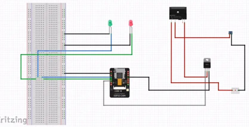
Explanation of the schematic diagram of Electrical Socket to Smart Plug Socket with ESP32 CAM Arduino Blynk app project.
The circuit diagram shown above used the TIP41C NPN transistor to form a common emitter follower configuration. The 5V solid state relay is turned on and off without a based transistor since the ESP32-CAM dev board has a maximum out put voltage of 3.3V.
Two LEDs were connected in the circuit to show a blink without delay and also to visualize when the 5V relay is turned on and off from the Blynk app. These were tested without no current limiting resistors and they worked just fine. The PCB socket was used to connected the electrical wire plug. All Neutral lines were connected together. While the live line was controlled by the 5V solid state relay output. This is shown in the second breadboard schematic below.
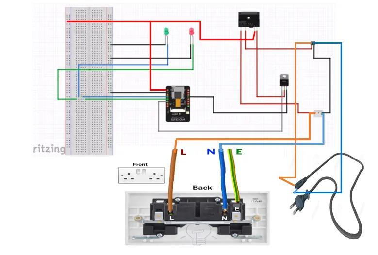
The circuit diagram above works but we recommend using a method to control the 5V solid state relay to be in a two stable states, either ON or OFF; a transistor logic level inverter be created. This comprised of two 220kΩ resistor and a 10kΩ resistor configured around an NPN transistor. The setup of this logic level shifter is to convert the 3.3V HIGH on the ESP32 CAM GPIO pin to 0V and the 0V LOW to 5V. The need for this is to ensure that the 5V solid state relay switch the 5-9V needed to power the project.
This was noticed practically that when switching DC voltage using the 5V solid state relay, the HIGH voltage won’t be enough when using boards like ESP32, ESP32 CAM, ESP8266, Raspberry pi etc. To know more about the calculations used for this simple logic level shifter follow this link.
Breadboard Assembly for Electrical Socket to Smart Plug Socket with ESP32 CAM Arduino Blynk app Project
The breadboard setup for How to Convert Electrical Socket to Smart Plug Socket with ESP32 CAM Arduino Blynk app
The ESP32-CAM development (dev) board was placed on the breadboard so that it can control the TIP41C NPN transistor through the base resistor 10kΩ. We attached the dev board to the breadboard and used the preformed jumper wires to finish off the rest of the connection between the transistor and the 5v solid state relay.
Powering the breadboard Assembly
The 5V power needed for this bread setup was drawn from the programming CH340 adapter. The 5V of the ESP32-CAM is connected to the Vcc pin on the CH340 adapter; this is how the ESP32 Cam is connected. The emitter of the Transistor must have a common ground (GND) with the ESP32 Cam.
CAUTIONS
When working with Alternating current (AC) voltages, care must be taken to avoid electric shocks. The best way to control the flow of AC voltage through the socket outlet is to use the PCB socket header and terminate the wires carefully. The following steps are observed judiciously.
Step 1:
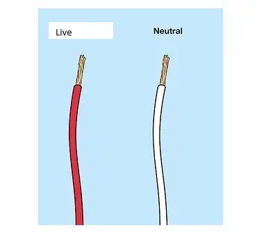
Strip off/Peel off the insulation AC wire terminals to expose the Live and Neutral wires to source the AC voltage to the PCB header. Screw and terminate these AC cables to the PCB header socket and ensure they are tight and firm.
Step 2:
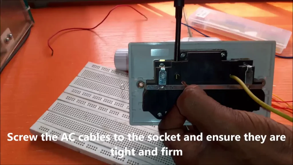
Open the electrical socket and safely attach the Live and Neutral cable. Ensure they are tight and firm.
Step 3:
Use the 5V solid state relay to interrupt the AC Live (L) wire. This is shown in the schematic and breadboard diagram above. The remote control would talk to the ESP32-CAM development board and it will talk to the 5V solid state relay and tell it when it should turn on the AC socket.
Step 4:
Connect the rest of the wires to the 5v solid state relay, ensuring that all the Neutral lines (wires) are connected together.
Step 5:
Use insulation tape to insulate and isolate all exposed AC voltage wires joined together. This will reduce the electric shock when the system is powered.
Setting Up the Blynk Control.
Step 1: Download the Blynk app
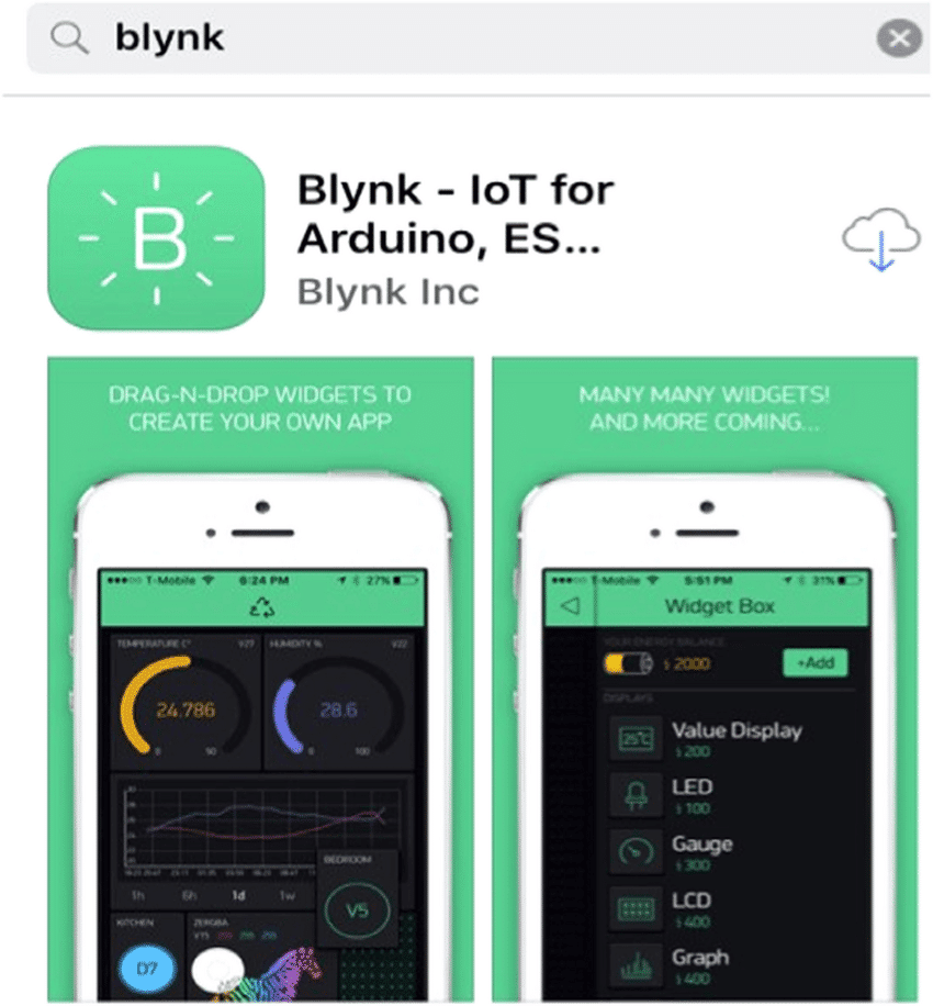
Open the respective app store for your device and find Blynk legacy. Please get the Blynk legacy version because that was used for this project. However, if you can’t use this version, kindly leave a comment in the comment section so that we could tell you how to use the latest version of Blynk IoT app for this electrical socket to smart plug socket with ESP32 CAM Arduino Blynk app project.
Step 2: Installing the Blynk app
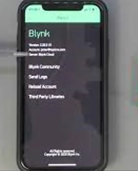
We installed the app on our android or iPhone device as shown in the picture above.
Step 3: Create New project
After successful installation, we signed up or signed since we already have an account and click on New Project as shown below.
Step 4: Pick a name for your new Project
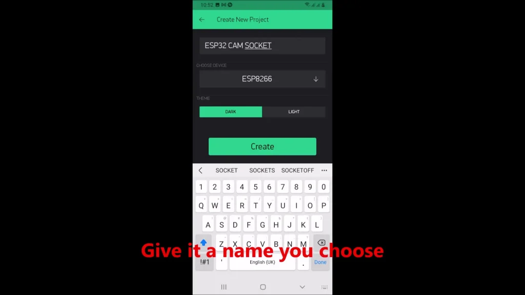
After setting the name of the project click, we selected our device type, and click create.
Step 5: Retrieve the token for Electrical Socket to Smart Plug Socket with ESP32 CAM Arduino Blynk app project
We went to our mailbox or alternatively our Blynk dashboard to copy the token. This would be used in the Arduino code later.
Step 6: Create our GUI design
We clicked on the add button on the upper right side and add the button widget. Configure this button widget by clicking on it and selecting where the virtual pin is selected.
This was saved and it was done.
Programming the ESP32-CAM.
We removed the ESP32-CAM from the breadboard and placed it onto the ESP32-Cam programmer adapter. We connected the USB flex to the port of the programmer. The programmer used a type B USB flex to its USB programmer as shown here below. This was connected this cable to our PC, the power LED on the programmer came on. We opened the Arduino IDE and copied the code below and compiled it successfully.
The Arduino source code for converting electrical socket to smart plug socket with ESP32 CAM Arduino Blynk app.
#define BLYNK_PRINT Serial
#include <WiFi.h>
#include <WiFiClient.h>
#include <BlynkSimpleEsp32.h>

//int led_gpio = 13;

#define Authorization_key "CjMXMZ3xjcbpG7gtnSPTFisJFkJ3WxF9" //EExmWR-3B8jC7H0ttOzr9qmtAciGW8DR
#define SSID "AncII"       // replace with your SSID
#define Password "eureka26"           //replace with your password

void setup() {
  //pinMode(led_gpio, OUTPUT);
  Serial.begin(115200);
  delay(10);
  WiFi.begin(SSID, Password);
  while (WiFi.status() != WL_CONNECTED) {
  delay(500);
  Serial.print(".");
  }
  Blynk.begin(Authorization_key,SSID,Password);
}
void loop(){
    Blynk.run();
}
Arduino Source code (sketch) Explanation.
The Arduino sketch given above began with including the various libraries from Blynk and WiFi connectivity; The Authentication Key was inserted from the email sent by Blynk after creating the project; so was the Internet WiFi USSID and Password too from an existing network with good internet access.
Once these are all set, we select our port number, select AI thinker ESP32-Cam as the development board then upload code.
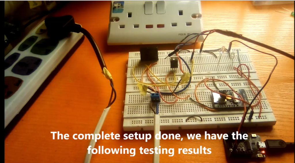
Testing the Final Setup for Electrical Socket to Smart Plug Socket with ESP32 CAM Arduino Blynk app project.
With the complete setup done, we have the following testing results as shown here.
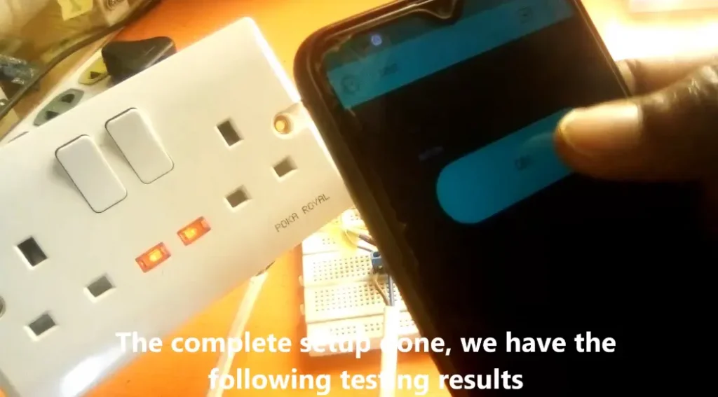
The button on the phone would allow us to turn the electrical socket into a smart plug socket. we can turn it on and off remotely from anywhere around the globe.
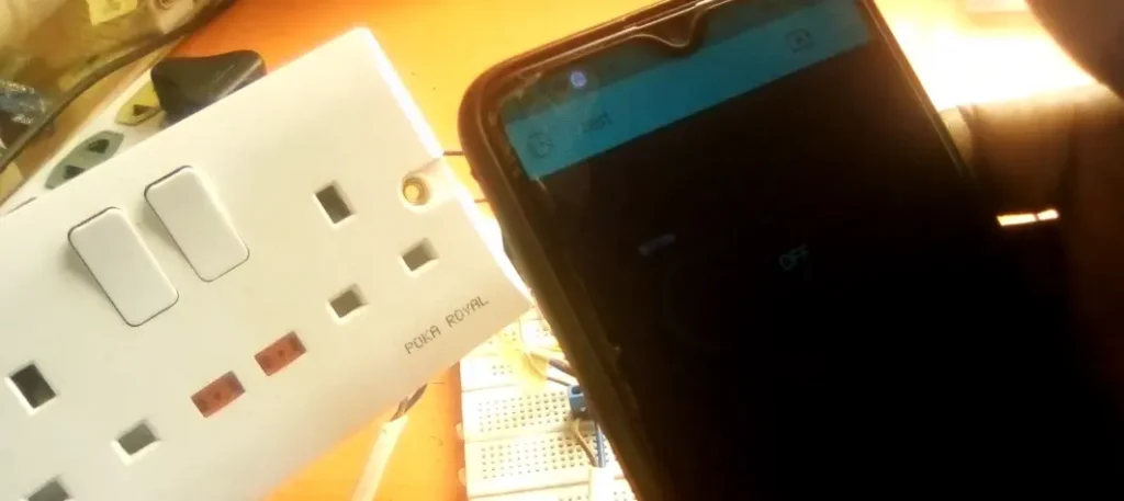
The downside to this is the manual switch on the socket, this can be rectified for forcefully removing the switch and ensuring no more manual controls.
Once we are connected to the internet, the setup works nicely; as expected!
Conclusion:
The project was aimed at using IoT to control an electrical socket via a mobile app. We have successfully shown that we can convert electrical socket to smart plug socket with ESP32 CAM, Arduino and Blynk app. Do you think you can do the same or even more than this? Kindly let us know by commenting below. Also if you have any questions, leave us a message in the comment section or on our Whatsapp handle or telegram group.
Don’t forget to share this post if you like it. You can read the next post on:
IoT Control Light bulb using ESP32 IoT Control of DC rechargeable home Fan.
See you on the next post.
Thank You.

