Introduction
Home automation continues to evolve with the help of affordable microcontrollers and IoT platforms. One of the most powerful combinations for beginners and advanced makers is the ESP32-CAM paired with the Blynk mobile app. Together, they allow you to control home appliances remotely while also providing live camera monitoring from anywhere in the world.
This tutorial is about Arduino Home Automation Using ESP32 CAM and Blynk app. The ESP32 CAM development board is used to control the speed of a rechargeable DC Fan at home using a vertical slider on an android app call the Blynk app. This is the second installment of our Home Automation Project design, you can read the first here. The tutorial will ensure that we control the Fan speed remotely from anywhere around the globe. That means we can run the DC fan at Maximum speed, turn the DC fan off or even keep it going at the speed we desire. We will be listing out the exact components and modules used in this ESP32 CAM project. The explanations of the circuit diagram connection, the ESP32 CAM Blynk code as well as the setting of the design will be well-detailed. Be sure to read through to the end.
The ESP32 CAM: An Overview.
The ESP32-CAM is a compact development board built around the ESP32 chip and integrated OV2640 camera. What makes this board exceptional is its ability to combine Wi-Fi, Bluetooth, video streaming, and GPIO control in a tiny, low-cost package.
With just a few external components and a stable 5V supply, the ESP32-CAM can perform several functions simultaneously: capturing images, streaming video, connecting to the internet, and controlling relays.
This versatility makes it a perfect choice for home automation projects—especially when video monitoring is part of the design.
The ESP32 is a powerful microcontroller platform that has been designed for low-cost, high-performance applications. It offers a wide range of features and can be used in a variety of devices, including security cameras. First, we will need to acquire the necessary hardware and software. The ESP32 camera module can be purchased from our online shop.
The ESP32-CAM Specifications
The ESP32-CAM is based upon the ESP32-S development board, it has a lot of similarities. The following specs are outlined for it.
- Computing power up to 600 DMIPS
- 520 KB SRAM plus 4 MB PSRAM
- Multiple Sleep modes
- Firmware Over the Air (FOTA) upgrades possible
- 9 GPIO ports
- 802.11b/g/n Wi-Fi
- Bluetooth 4.2 with BLE
- UART, SPI, I2C and PWM interfaces
- Clock speed up to 160 MHz
The ESP32 Camera Specifications
The ESP32-CAM includes an OV2640 camera module. The device also supports OV7670 cameras. The OV2640 has the following specifications:
- 2 Megapixel sensor
- Array size UXGA 1622×1200
- Output formats include YUV422, YUV420, RGB565, RGB555 and 8-bit compressed data
- Image transfer rate of 15 to 60 fps
More details can be looked at here
Components needed for this tutorial
- ESP32 cam development board
- Solderless board (breadboard)
- Male jumper wires
- PCB socket header
- Preformed jumper wires
- 5V DC rechargeable fan
- AC Voltage Wire plug
- TIP41C NPN transistor
- ESP32 CAM programmer board
Arduino Home Automation Using ESP32 Cam and Blynk: The Schematic Diagram And Breadboard Assembly.
Since there are many components soldered already on the bottom of the ESP32 CAM, We recommend using a solderless breadboard when experimenting with this tutorial. The use of female Dupont connectors is recommended.
The Circuit Diagram
Explanation of the Circuit Diagram
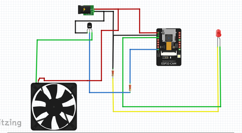
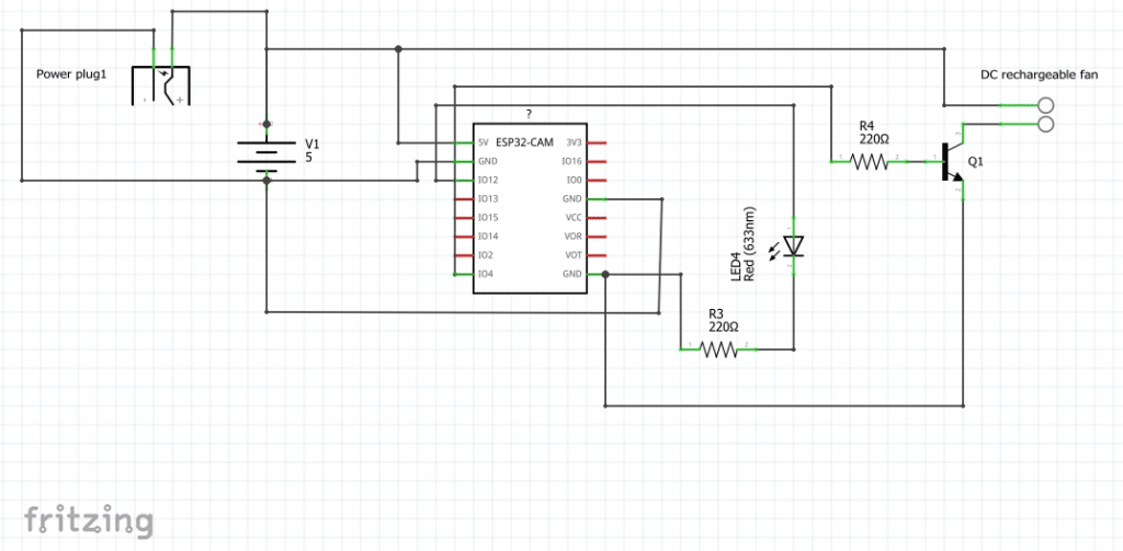
The circuit diagram shows that the ESP32 Cam was connected or powered by a 5V input power rail. This can be easily gotten from the ESP32 CAM programming board. This Adaptable CH340 programmer has an output source for 5V and GND.
The circuit diagram has an indicator LED that is connected to GPIO pin 12 on the ESP32 CAM with a current limiting 220Ω resistor that stops the LED from burning out. The LED indicator here was used to show that the program was working as expected. Later in the code section; a blink-without-delay code will be injected just for aesthetic effect.
To control the DC fan, we needed to use a transistor that is configured in an amplifier mode. By connecting the DC rechargeable fan in the Common Emitter configuration, we were able to use pulse width modulation (PWM) at the base to control the rate of circular movement (speed) of the DC fan for this Arduino Home Automation Using ESP32 CAM and Blynk app instructible.
The DC rechargeable fan for this Arduino Home Automation Using ESP32 CAM and Blynk app tutorial operates on 5-9V DC voltage. However, the ESP32 CAM operates on 5V. For this tutorial, we used only the 5V to control the DC fan and the ESP32 CAM. However, if you want to run the DC fan at is maximum speed by using a 9V DC power supply, you may need a DC-Dc buck converter. This would step down the DC voltage to 5V which is suitable for the ESP32 CAM to operate.
The circuit centers around the ESP32-CAM and a relay module that switches home appliances. The relay is connected to one of the GPIO pins on the ESP32-CAM, while the board itself is powered by a regulated 5V supply.
In the circuit diagram, the relay controls the live AC line of the appliance. The ESP32-CAM sends a digital HIGH or LOW signal to toggle the relay ON or OFF. Meanwhile, the camera module remains active, allowing remote video monitoring through the Blynk interface.
A stable power supply is crucial because the ESP32-CAM tends to draw more current during Wi-Fi transmissions. Once everything is connected properly, the system forms a complete IoT-controlled home automation unit.
Breadboard Assembly for Arduino Home Automation Using ESP32 Cam and Blynk
Before finalizing the hardware, the entire setup is first assembled on a breadboard. This makes it easier to troubleshoot and test each part of the circuit.
The ESP32-CAM is placed at the center of the breadboard, while the relay module sits beside it. Jumpers are used to connect 5V, GND, and the control pin between the two modules. The breadboard also hosts the FTDI or USB-to-TTL programmer used during code uploading.
At this stage, you can verify that the ESP32-CAM powers up correctly, connects to the Wi-Fi network, and communicates with Blynk. Once the relay responds to commands within the Blynk app, the assembly can be moved into a safe housing.
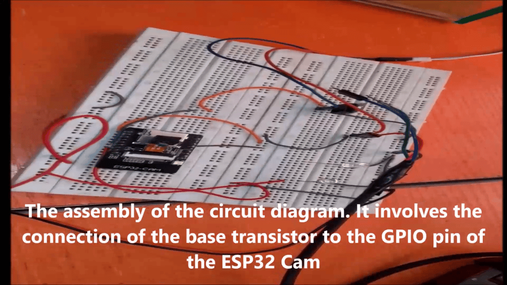
Assembly of the circuit is on a solderless board shown in the picture above. The power rails are maintained as to be expected and preformed jumper wires are used to finish the connections. The DC Rechargeable fan used for this Arduino Home Automation Using ESP32 CAM and Blynk app tutorial was a DC rechargeable hand fan. It was stripped of its internal components and only the Fan motor and blade housing were relevant.
Setting up the Blynk App for Arduino Home Automation Using ESP32 Cam and Blynk
Step 1: Download the Blynk app
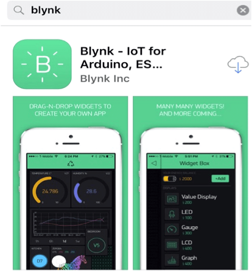
Open the respective app store for your device and find Blynk legacy. The Blynk legacy version was used for this project. However, if you can’t use this version, kindly leave a comment in the comment section so that we could tell you how to use the latest version of Blynk IoT app for this Arduino Home Automation Using ESP32 CAM and Blynk app tutorial.
Step 2: Install the Blynk app
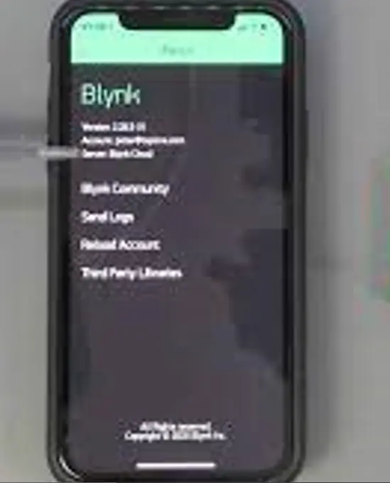
Install the app on your android or iPhone device as shown in the picture above.
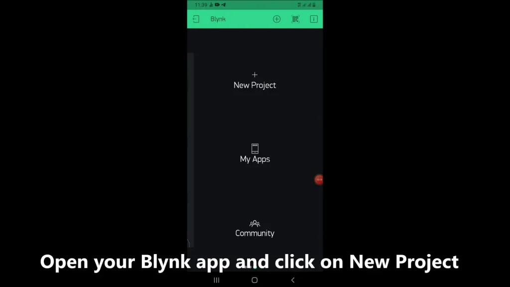
Step 3: Create New project
After successful installation, sign up or sign in if you already have an account and click on New Project as shown below.
Step 4: Pick a name for your new Project
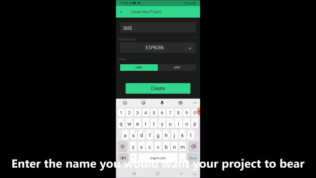
After setting the name of the project click, select your device type as ESP32, and click create.
Step 5: Retrieve the token for this Arduino Home Automation Using ESP32 Cam and Blynk project
Go to your mailbox or to your Blynk dashboard to copy the token. Use this in the Arduino code.
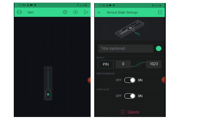
Step 6: Create the GUI design for Arduino Home Automation Using ESP32 Cam and Blynk project.
Click on the add button on the upper right side and add the vertical widget. Click on it, select where the desired virtual pin. The PWM output is either 255 or 1023. For this Arduino Home Automation Using ESP32 CAM and Blynk app tutorial, we left it at 1023. Save this and it is done.
The Arduino Sketch
Below is the Arduino code.
#define BLYNK_PRINT Serial
#include <WiFi.h>
#include <WiFiClient.h>
#include <BlynkSimpleEsp32.h>

const int ledPin =  12;// the number of the LED pin

// Variables will change:
int ledState = LOW;             // ledState used to set the LED

// Generally, you should use "unsigned long" for variables that hold time
// The value will quickly become too large for an int to store
unsigned long previousMillis = 0;        // will store last time LED was updated

// constants won't change:
const long interval = 1000;

const int fanPin = 4;
int fanWidget;

#define Authorization_key "a6SdaWEnnAoXTmrYhX_GPvQ8hq_fDEvw" //EExmWR-3B8jC7H0ttOzr9qmtAciGW8DR
#define SSID "***"       // replace with your SSID
#define Password "***"           //replace with your password

// setting PWM properties
const int freq = 5000;
const int ledChannel3 = 0;
const int resolution = 8;


BLYNK_WRITE(V2) {
fanWidget = param.asInt();
ledcWrite(ledChannel3, fanWidget);
Serial.println(fanWidget);
}

void setup() {
  Serial.begin(115200);
  delay(10);
  WiFi.begin(SSID, Password);
  while (WiFi.status() != WL_CONNECTED) {
  delay(500);
  Serial.print(".");
  }
  pinMode(ledPin, OUTPUT);
  ledcSetup(ledChannel3, freq, resolution);
  // attach the channel to the GPIO to be controlled
  ledcAttachPin(fanPin, ledChannel3);
  Blynk.begin(Authorization_key,SSID,Password);
}

void blinkky(){
  unsigned long currentMillis = millis();

  if (currentMillis - previousMillis >= interval) {
    // save the last time you blinked the LED
    previousMillis = currentMillis;

    // if the LED is off turn it on and vice-versa:
    if (ledState == LOW) {
      ledState = HIGH;
    } else {
      ledState = LOW;
    }

    // set the LED with the ledState of the variable:
    digitalWrite(ledPin, ledState);
  }
}
void loop(){
  blinkky();
    Blynk.run();
  }
Explanation of the Arduino Sketch.
The Arduino sketch handles the Wi-Fi setup, Blynk communication, and relay control logic. When the ESP32-CAM boots, it connects to your Wi-Fi network using the credentials defined in the code.
The Blynk library listens for commands sent from the app. When a widget (like a button) is toggled, the ESP32-CAM receives the instruction and switches the relay accordingly. The sketch also configures the camera stream, enabling you to view live footage on your mobile device.
The code is straightforward: initialize Wi-Fi, connect to Blynk, set pin modes for the relay, and manage the camera server. This structure keeps the sketch clean and easy to expand for multiple relays or sensors.
The esp32 cam Blynk code made use of some Blynk libraries. The LED pin was set and then the WiFi user name and password were also set. The pulse-width modulation (PWM) properties were set and a function was used to check and control the fan speed.
Testing the Arduino Home Automation Using ESP32 Cam and Blynk
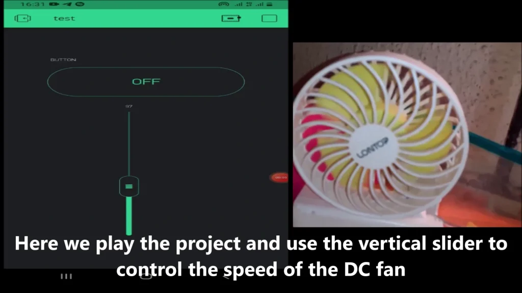
Upload the Arduino sketch and power the hardware circuitry. Open the Blynk app and press the play button. Once the app gets internet access and it can talk to the ESP32 CAM, it will show connected. Using the vertical slider we can control the Fan. The Lowest height on the slider will cause the DC fan to turn off while the highest height will make it operate at its maximum speed. Anything in between these two would make the fan run at a speed proportional to the height on the vertical widget on the Blynk app. Please watch the YouTube video below to see the project in action.
Conclusion.
In conclusion, we have been able to demonstrate how easy it is to control a DC rechargeable Fan with ESP32 CAM using this post of Arduino Home Automation Using ESP32 CAM and Blynk app . The test above showed that this project worked. Follow the steps shown here to reproduce the project. Just follow the step-by-step guide detailed in this post. As a challenge, you may want to control an alternating current (AC) fan rather than a DC Fan you can try it out or post a question in the comment section so that we can make a post and a video on that. Be sure to check out our previous post on how to control a AC light bulb using ESP32 CAM.
Please kindly comment about how you feel about this project. Don’t forget to share and like.
Thank you.

