Introduction
The ESP32-CAM is one of the most versatile and affordable boards for building a home automation system. With built-in Wi-Fi and an onboard camera, it allows you to control appliances remotely while also monitoring your home in real time. This project focuses on how to use the ESP32-CAM as the central control unit for home automation—handling switching operations and offering camera surveillance from anywhere.
Whether you’re turning lights ON/OFF, activating a fan, or checking your home remotely, the ESP32-CAM provides a smart and efficient solution.
In today’s tutorial, we step into the world of IoT (internet of things) automation and surveillance using Arduino and ESP32 cam for home automation. This tutorial ESP32 Cam for home automation focuses on trying to blink the AC light bulb using the GPIO pin of the esp32-cam. This is on the path that leads to using ESP32 Cam to do home automation and surveillance.
This will allow us to control home actuators like light bulbs, ventilation fans, AC load-point sockets and still be able to stream video footage remotely from anywhere in the world. Already, we know that we can stream video surveillance using the esp32-cam, the focus now is to also control AC actuator or actuators in other to complete the task in the home automation. Once we can be able to control or blink the AC light bulb on and off, we can as well do home automation using ESP Wi-Fi in IoT. To get started, the following materials are needed.
Materials/Components for ESP32 Cam for Home Automation
Breadboard…buy here
5V solid-state relay…buy here
PCB socket
Preformed jumper wires… buy here
A pair of screwdrivers
ESP32-Cam development board…buy here
A pair of LEDs (red and green color types)… buy here
ESP32-CAM programmer… buy here
AC wireless plug
AC light bulb (energy-saving type)
Current limiting resistor 220kOhms
ESP32 Cam for Home Automation: Circuit Diagram
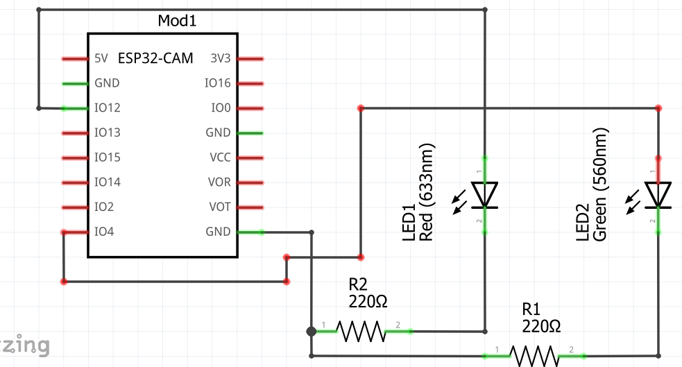
The circuit diagram shown above is the schematic for the ESP32 cam LED blinking. The diagram makes use of the Programmer to power the ESP32 Cam development board. The circuit diagram of the ESP32 cam connection depicts two connections of LEDs to its GPIO (general purpose input output) pins. One for turning the red LED. The red LED was used to know when the ESP-32 Cam was powered on whereas the green LED was used to show the blinking state. The red LED was connected to GPIO pin 4. A current limiting resistor was connected in series to the green LED.
Connection On the Breadboard
The schematic of this Arduino home automation was assembled on a breadboard because it was easier to correct any mistake that is made on it than when it was soldered on a Veroboard. To know more about how to use a breadboard, kindly search on Google or leave us a message in the comment section.
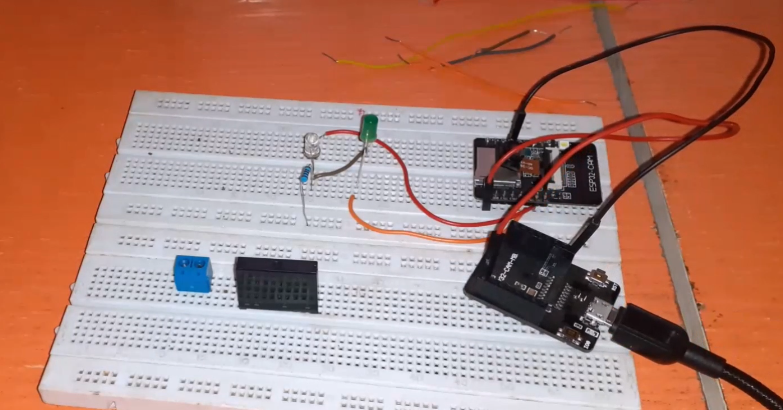
The connection was done by connecting the anode of the green LED to the GPIO pin 4 of the ESP32 Cam dev board and using a current limiting resistor to connect the Cathode of the LED to the ground. The same procedure was repeated for the red LED. Except that the red LED anode pin was connected to GPIO 2 on the ESP32 Cam. Some preformed jumper wires were used to finish the connection whereas the power rails, 5V, and GND sources were drawn from the ESP32 cam programmer DC power rail pins.
Alternatively, the onboard LED of the ESP32 cam development board can equally be used. However, care must be taken to change this pin assignment in the Arduino sketch given below. To use this, the sketch below is used. Refer to the YouTube video for this demonstration.
The Arduino Source Code And Explanation.
//define and declare where the LEDs are connected on the ESP32 cam
#define redLedPin 12
#define greenLedPin 4

void setup(){
//make these LEDs as outputs
pinMode(redLedPin, OUTPUT);
pinMode(greenLedPin, OUTPUT);

//turn the red LED permanently on
digitalWrite(redLedPin, HIGH);
}

void loop(){
//blink the green LED
digitalWrite(greenLedPin, HIGH);
delay(1000);
digitalWrite(greenLedPin, LOW);
delay(1000);
}
For this home automation using ESP32 cam, the pin on is ESP32 Cam, where the green LED, was connected was assigned a variable greenLedPin. And this was declared to be GPIO pin 4 on the ESP32 Cam board. The setup function made these pins outputs. The next line of code calls the red LED to be permanently turned on after this; whereas in the loop function, the green LED was blinked every second.
Blinking the AC Light Bulb
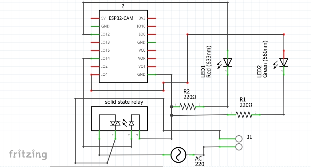
The circuit diagram of the DIY (Do-It-Yourself) AC bulb blinking light is shown above. The schematic showed that a 5V solid-state relay was connected to GPIO pin 14. The anode of the 5V solid state relay was connected directly to this GPIO pin on the ESP32 Cam for home automation. This would work since we are trying to cut off AC voltages during the digital LOW state of the ESp32 Cam development board and allow AC voltages to flow through during the digital HIGH of the state of the ESP32 cam.
The above method of connecting the anode of the 5V solid state relay to the Control GPIO pin of the ESP32 Cam may not always work for some cases. This can be solved by using an NPN transitor. For this demonstration, we used the famous TIP41C transistor. This done according to the Arduino sketch below, would create a blinking bulb with relay.
The J1 header pin is where the AC light bulb lamp holder is connected and the AC ight bulb is connected or screwed for lighting effect.
The Arduino Sketch
//define and declare where the LEDs are connected on the ESP32 cam
#define redLedPin 12
#define greenLedPin 4
//define and declare where the relay anode pin is connected
#define relayPin 14

void setup(){
//make these LEDs as outputs
pinMode(redLedPin, OUTPUT);
pinMode(greenLedPin, OUTPUT);
//make the relay pin an output
pinMode(relayPin, OUTPUT);

//turn the red LED permanently on
digitalWrite(redLedPin, HIGH);
}

void loop(){
//turn on the green LED for 1 sec
digitalWrite(greenLedPin, HIGH);
//turn on the AC light bulb for 1 sec
digitalWrite(relayPin, HIGH);
delay(1000);
//turn off the AC light bulb for 1 sec
digitalWrite(relayPin, LOW);
digitalWrite(greenLedPin, LOW);
delay(1000);
}
The Result:
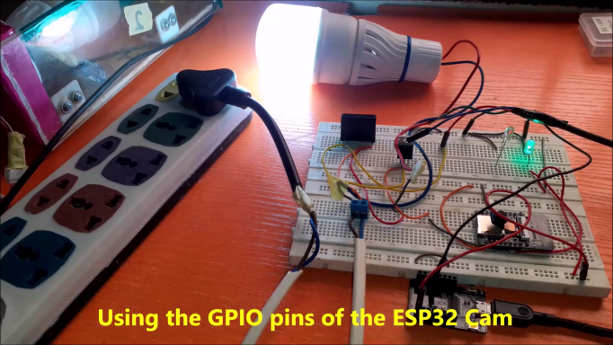
The AC light bulb blinked every second. This means that we have successfully controlled the On-state and the Off-state of the AC light bulb. Thereby making it blink. The next thing is to make this remotely controlled using the Wi-Fi of the ESP32 cam.
Conclusion
So far we have learnt how to use Arduino and ESP32 Cam For Home Automation. Feel free to drop any questions in the comment section. Thank you.

