The project design IoT based pump control irrigation system system using ESP32 Arduino focus on building an irrigation system model that checks on model sensors like temperature, soil moisture content, reservoir/tank water level, and displays this on an Blynk Internet of Things (IoT) dashboard. The model project design automatically irrigates the soil when the water level content is low, it also has an controls on the IoT dashboard where a user can pump water into the reservoir tank by will. The design also sends an alert when any of the monitoring parameter are off. Let us go step-by-step to know how this IoT based pump control irrigation system using ESP32 Arduino was built. Ensure you read until the end.
IoT based pump control irrigation system using ESP32 Arduino: Components and Materials Needed
| S/N | ITEMS | QUANTITY |
| 1 | ESP32 DEV BOARD | 1 |
| 2 | DC PUMP | 2 |
| 3 | TRANSISTOR | 2 |
| 4 | PLASTIC CONTAINER | 2 |
| 5 | USB POWER JACK | 1 |
| 6 | MODEL FARM | 1 |
| 7 | ULTRASONIC DISTANCE SENSOR | 1 |
| 8 | PLASTIC CASING | 1 |
| 9 | VERO BOARD | 1 |
| 10 | CONNECTING WIRES | 3 |
| 11 | PROGRAMMING AND LIBRARIES UPLOAD | 1 |
| 12 | GLUE STICKS | 2 |
| 13 | SOLDERING LEAD | 1 |
| 14 | SOLDERING IRON | 1 |
| 15 | SOIL MOISTURE SENSOR | 1 |
| 16 | 5V DC PUMP | 2 |
| HEADER PIN | 1 | |
| 18 | MISCELLENOUS |
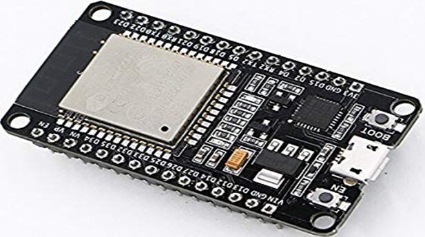
The ESP32 development (dev) board was used because of its fantatic features. It came with lot of processing power, having two 32 bit cores, and enough memory. It possessed both Bluetooth and WiFi capability on its chip. And it could be programmed to enter low-power deep sleep .
Specifications:
- The ESP32 possess dual core (meaning it 2 processors).
- It possess Wi-Fi built-in capability.
- It possessed Bluetooth capability.
- It can run 32 bit programs
- Clock frequency up to 240MHz
- It has 512 Kb Random Access Memory (RAM)
- It has 30 pins with 15 on each sides.
- It has other peripheral features like capacitive touch, ADCs, DACs, UART, SPI, I2C and much more.
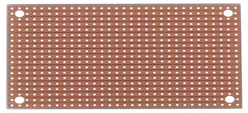
The Perforated boards (perf boards or Veroboard) is a plastic perforated insulator used to arrange configurations of electronic design to finished work. At first, our project was first modelled on a Breadboard, which is a detachable platform, which gives room for error making, removing of components and reattachment of the components. Unlike the Breadboard, the perfboard, is used to solder these components together and once done, is usually very difficult to remove them without applying heat or destroying the components by the use of force.
The Schematic Diagram
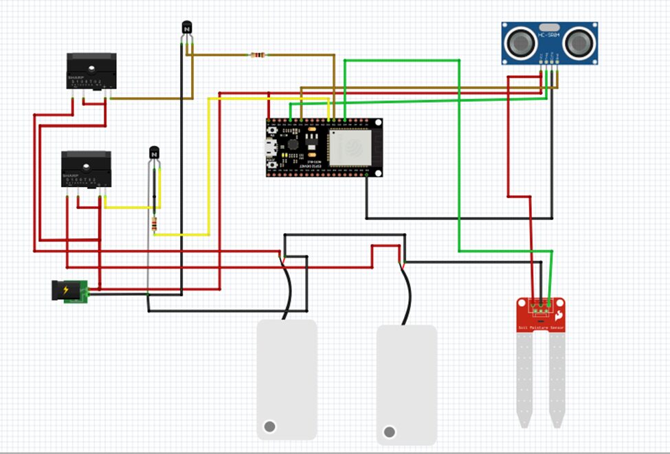
The Explanation
The pictorial schematic diagram above shows how the entire circuitry was assembled. This circuit diagram was drawn using Fritzing IDE. The above circuit is the breadboard view section. As shown the whole design was dependent on the ESP32 dev board. The Ultrasonic sensor was connected to the MCU using two wire data method. The trigger (trig) pin was connected to the digital pin 13 and the echo pin of the ultrasonic sensor was connected to the digital pin 12. The power rails of the ultrasonic sensor was connected to the 5V and the GND pins respectively. This is in parallel to the power rail from which the ESP32 dev board was powered from too.
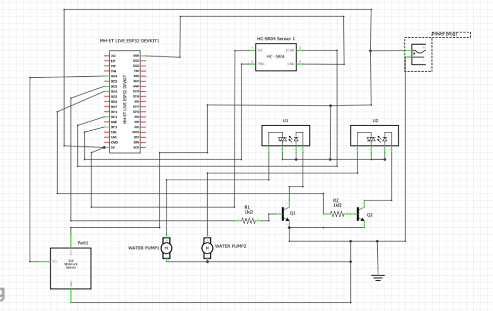
As shown in the schematic diagram above, the two DC pumps were used for different purposes. One of the DC pump served for irrigation, while the other one was to ensure that there is enough water in the reservoir tank for irrigation. Since the DC pumps don’t drag so much current, we used a pair of NPN transistors to construct a common emitter follower which we used to turn on the DC pumps when needed and turn them off when we needed them to stay turned off.
Modelling and Construction of the IoT based pump control irrigation system using ESP32 Arduino
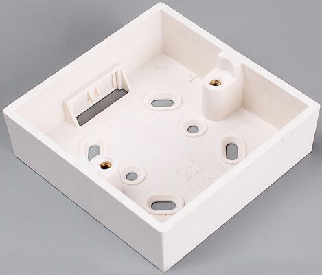
The casing was done using a white plastic box of dimension 3×3”. It was suitable to house the components and wiring. The power supply plug was connected and powered on to testing the design working properly.
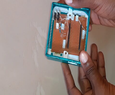
This later wrapped with a blue polyethylene material and it housed the veroboard that has the microcontroller and socket header for the other components as shown in figure above.
Modelling the Irrigation Garden
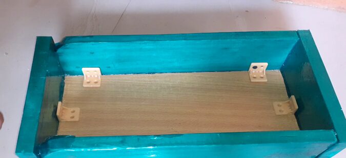
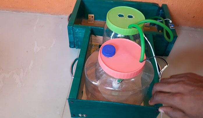
This involved the prototyping of the farm to be irrigated, the water storage tank and the river or waterbody to be demonstrated with. To model the whole project, a wooden platform was constructed containing two wooden boxes. The box for the model farm was done using a dimensions of 30cm × 15cm × 10cm. while the box for housing the reservoirs was 20cm × 11cm × 10cm.
The construction of the IoT based pump control irrigation system using ESP32 Arduino was done using soldering and coupling of active circuit. The soldering was done on the VERO Board using a 60 watts soldering, the components were properly arranged by following the designed circuit diagram of the project.
Programming the Project Design
 // See the Device Info tab, or Template settings
#define BLYNK_TEMPLATE_ID "TMPLYH5GKVJ9"
#define BLYNK_DEVICE_NAME "IoT Based Water Pump Control"
#define BLYNK_AUTH_TOKEN "9UNYu0-4YQSM5BGvY0pFavvxJ-VdTLff"


// Comment this out to disable prints and save space
#define BLYNK_PRINT Serial


#include <WiFi.h>
#include <WiFiClient.h>
#include <BlynkSimpleEsp32.h>

char auth[] = BLYNK_AUTH_TOKEN;

// Your WiFi credentials.
// Set password to "" for open networks.
char ssid[] = "AncII";
char pass[] = "eureka26";

long duration;
float cm, distance;
int toggleState_1, toggleState_2;
 int soilWaterLevel;

#define trigPin 13
#define echoPin 12
#define RelayPin1 32
#define RelayPin2 33


BLYNK_CONNECTED() {
  // Request the latest state from the server
  Blynk.syncVirtual(V0);
  Blynk.syncVirtual(V1);
  Blynk.syncVirtual(V2);
  Blynk.syncVirtual(V3);
}


void setup(){
  // Debug console
  Serial.begin(115200);
   pinMode(trigPin, OUTPUT);
   pinMode(echoPin, INPUT);
   pinMode(RelayPin1, OUTPUT);
   pinMode(RelayPin2, OUTPUT);

  Blynk.begin(auth, ssid, pass);
  // You can also specify server:
  //Blynk.begin(auth, ssid, pass, "blynk.cloud", 80);
  //Blynk.begin(auth, ssid, pass, IPAddress(192,168,1,100), 8080);
}


float uSensor(float numfactor, float denumFactor){
  digitalWrite(trigPin, LOW);
  delayMicroseconds(2);
  digitalWrite(trigPin, HIGH);
  delayMicroseconds(10);
  digitalWrite(trigPin, LOW);
  duration = pulseIn(echoPin, HIGH);
  distance = duration * (numfactor/denumFactor);
  distance = map(distance, 2.00, 18.20, 100.00, 0.00);


  if((distance >= 94)&&(distance < 100)){
   digitalWrite(RelayPin1, LOW);
   Serial.println("water stopped pumping into Irrigation Tank");
  }

  else{
    Serial.println("ariba");
  }

  Serial.print("Tank Water Level: ");
 Serial.println(distance);
  return distance;
}

int soilMoistureLevel(int sensorPin){
 soilWaterLevel = analogRead(sensorPin);
 soilWaterLevel = map(soilWaterLevel, 0, 4095, 100, 0);
 soilWaterLevel = map(soilWaterLevel, 0, 71, 0, 100);
 Serial.print("Soil Moiture Level: ");
 Serial.println(soilWaterLevel);

if(soilWaterLevel <= 40){
 Serial.println("soil needs water");
}


if((soilWaterLevel >= 87) && (soilWaterLevel <= 99)){
  digitalWrite(RelayPin2, LOW);
}
 return  soilWaterLevel;

}


void sendSensor(){
  Blynk.virtualWrite(V3, soilWaterLevel);
  Blynk.virtualWrite(V2, distance);

 }


BLYNK_WRITE(V0) {
  toggleState_1 = param.asInt();
 if(distance <= 92.00){
  if(toggleState_1 == 0){
    digitalWrite(RelayPin1, LOW);
  }
  else {
    digitalWrite(RelayPin1, HIGH);
  }
}
}


BLYNK_WRITE(V1) {
  toggleState_2 = param.asInt();

 if(soilWaterLevel <  88  ){
  if(toggleState_2 == 0){
    digitalWrite(RelayPin2, LOW);
  }
  else {
    digitalWrite(RelayPin2, HIGH);
  }

}
}


void loop(){
  uSensor(0.034, 2.0);
  soilMoistureLevel(34);
  sendSensor();
//  BLYNK_WRITE(V1);
//  BLYNK_WRITE(V2);

  Blynk.run();

}
Explanation of Arduino Source Code
Code line is 57 and 58 where we defined the place where the trig pin and the echo pin were connected to the esp32 development board respectively. Code line 22 and 23 created variables that would allow the Ultrasonic sensor to measure distance in inches and centimeter.
In the setup() function, we set these pinouts of the ultrasonic sensor (U.sensor) as input for the echo pin and output for the trig pin.
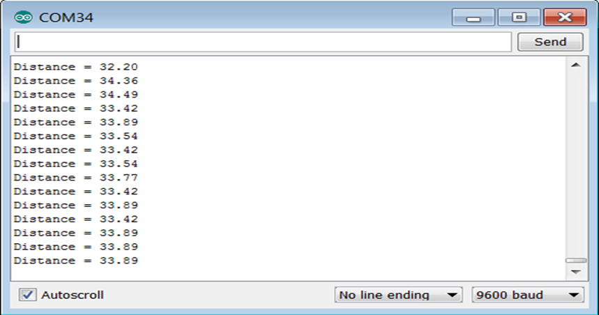
We created a custom function that was designated to measuring distance in centimetres using the U.sensor. this function was called. … in this function we the echo pin for some time then pulse input the trig using the pulseIn function. We calculated the distance measurement away from any obstacle which is hit by the sonar wave sent by the sensor transmitter and then echoed back to it and recieved by its receiver. The measure distance is then converted to centimetres (cm) using the formula shown in code line. The result is printed out on serial monitor using the syntax
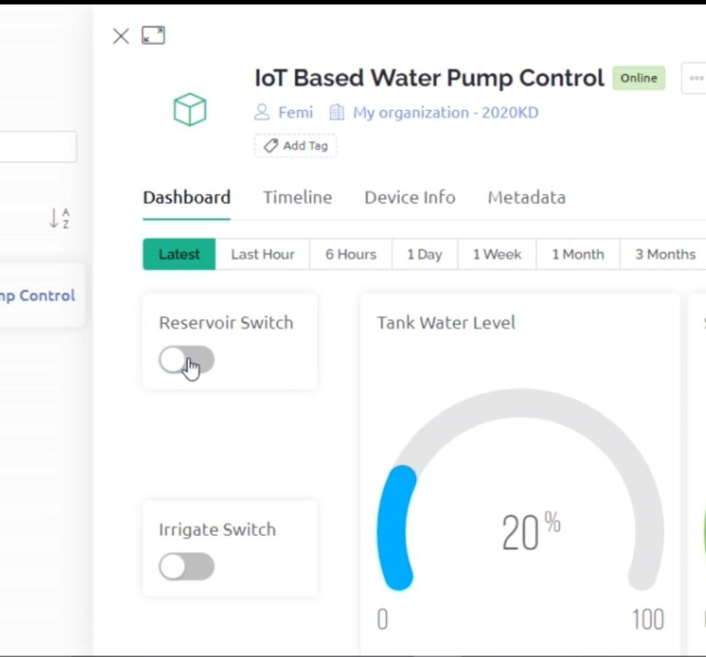
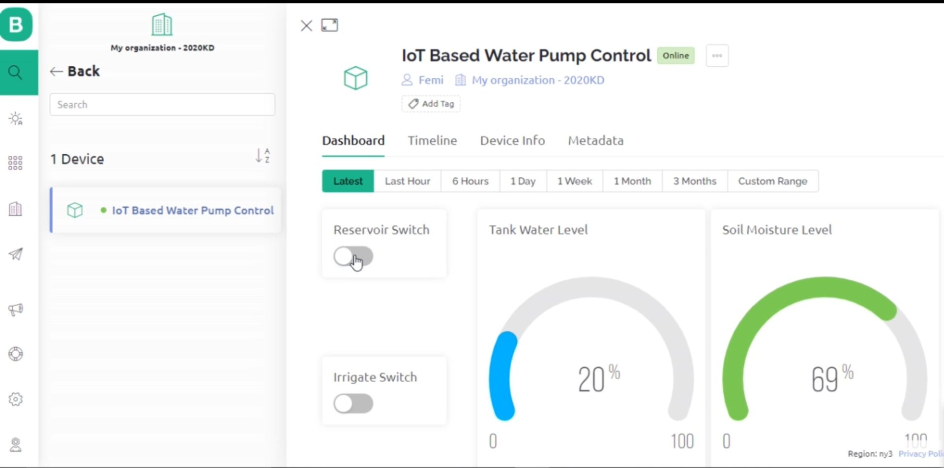
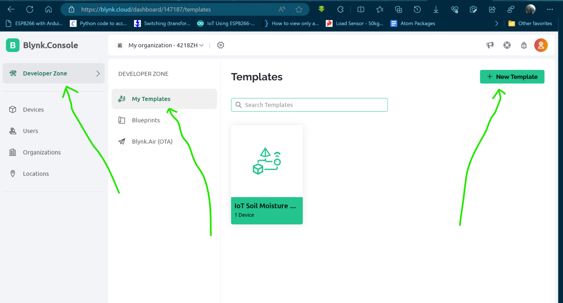
Designing and Setting Up the Blynk IoT Dashboard for IoT-based Pump Control Irrigation System
To begin the setting up of the Blynk dashboard, go to the Blynk platform and after creating an account. Login into your blynk dashboard and click on the “Developer zone”. There you can create a new template.
After naming your template, you get to set up Datastreams, Web Dashboard, Automations and Events.
Results and Testing of the IoT Based Pump control Irrigation System
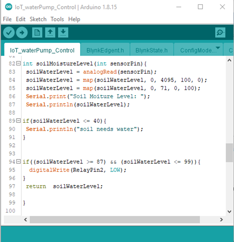
This was a custom function called soilMoistureLevel. In the function the MCU pin where the resistive soil moisture sensor was connected was read using the analog function analogRead(). This was then mapped from the 16-bit to a percentage level. However, this was found to be on 71. And so it led to another mapping of 0 to 100%. The serial print function was used to print the measure soil moisture content on the serial monitor.
An if statement was used to check then when the soil water level was low below or equivalent to 40% so that it could print “soil needs water’. And if the soil moisture level was abundant between the range of 87 to 99 %, it will turn off the relay pin that was responsible for pumping water into the model garden farm this is shown in code line 95.
Conclusion
The system design has been done successfully and it can automatically measure the soil moisture content in the model garden and check if there is enough water in the reservoir tank to irrigate the model garden. It can also alert the user when there is change in the parameters being monitored.

