Tag: Arduino

  • How to Interface an Ultrasonic Sensor with Arduino

    How to Interface an Ultrasonic Sensor with Arduino

    HCSRO4
    HCSRO4

    Ever wondered how bats navigate in total darkness? They use sound waves to “see.” Ultrasonic sensors work the same way — by sending and receiving sound waves beyond human hearing. In this guide, we’ll walk through how to interface an ultrasonic sensor with an Arduino Uno, write the code, and measure distances in centimeters, meters, and even kilometers.

    Whether you’re building a smart robot, a parking system, or a motion detector, this is a core skill every maker should know.


    What Is an Ultrasonic Sensor?

    An ultrasonic sensor is an electronic device that measures distance by sending out ultrasonic waves and measuring the time it takes for the echo to return.

    The most common model is the HC-SR04 ultrasonic sensor, which has:

    • Trigger pin: sends out the sound pulse
    • Echo pin: receives the reflected pulse
    • VCC: power pin (usually 5V)
    • GND: ground pin

    It’s like shouting into a canyon and measuring how long it takes for the echo to bounce back — simple but clever!


    How It Works (In Plain English)

    Here’s what happens step by step:

    1. The Arduino sends a signal to the sensor’s Trigger pin.
    2. The sensor emits an ultrasonic pulse.
    3. That pulse hits an object and reflects back.
    4. The Echo pin receives the returning sound wave.
    5. The Arduino calculates the distance using the time difference.

    The math is simple:

    Distance = (Time × Speed of Sound) / 2

    Since sound travels at about 343 m/s, this formula gives very accurate results — perfect for most DIY projects.


    Components You’ll Need

    To get started, gather the following:

    • Arduino Uno board
    • HC-SR04 Ultrasonic Sensor
    • Jumper wires (male to female)
    • Breadboard
    • USB cable (for programming)
    • Laptop or PC with Arduino IDE installed

    That’s it! No fancy equipment needed — just basic tools.


    Wiring the Ultrasonic Sensor to Arduino

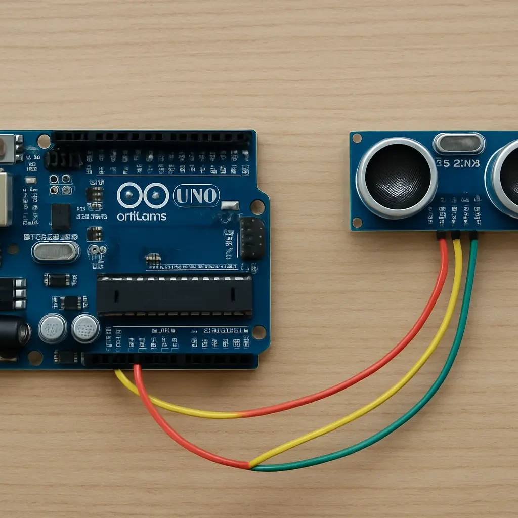
    Connecting the sensor is easy. Here’s the standard setup:

    • VCC → 5V on Arduino
    • GND → GND
    • Trig → Digital Pin 2
    • Echo → Digital Pin 3

    Make sure your connections are firm and correct. One loose wire can mess up your readings!

    Breadboard View

    Breadboard view
    Breadboard view

    Schematic Diagram

    Schematic Diagram
    Schematic Diagram

    Writing the Code

    Now comes the fun part — programming. Open your Arduino IDE and type in the following code:

    code hcsr04
    code hcsr04
    code hcsr04 2
    code hcsr04 2

    Upload the sketch, open your Serial Monitor, and watch your Arduino display distances in cm, m, and km in real time!


    Testing and Calibration

    Place an object in front of the sensor and gradually move it closer or farther away. You’ll notice the readings change dynamically.

    If your readings seem off:

    • Double-check your wiring.
    • Ensure your object is large and flat (like a book or box).
    • Avoid soft materials that absorb sound.

    Small adjustments can make a big difference in accuracy.


    Real-Life Applications of Ultrasonic Sensors

    real world applications of ultrasonic sensors
    real world applications of ultrasonic sensors

    You’ll find ultrasonic sensors everywhere! Here are a few ideas:

    • Smart parking systems — detect vehicles and empty spots.
    • Obstacle-avoiding robots — sense distance and change direction.
    • Water level detection — monitor tank levels without contact.
    • Proximity alarms — trigger a buzzer when someone comes close.

    Think of it as your electronic version of echolocation — just like bats, but smarter.


    Troubleshooting Common Issues

    ProblemPossible CauseSolution
    No reading on Serial MonitorWrong COM portSelect the correct port in Tools > Port
    Constant 0 or max readingLoose connectionCheck wiring
    Inaccurate valuesElectrical noiseAdd a small capacitor (100nF) between VCC and GND
    Unstable readingsInterferenceUse a stable power source or shield the sensor

    FAQs

    1. Can ultrasonic sensors detect transparent objects?
    Not reliably. They work best on solid, flat surfaces because sound waves pass through glass or thin materials.

    2. How far can the HC-SR04 measure?
    It typically measures between 2 cm to 400 cm (4 meters) accurately.

    3. Why does my sensor give unstable readings?
    It may be due to electrical noise, reflections, or incorrect wiring. Adding a capacitor or averaging multiple readings helps.

    4. Can I use multiple ultrasonic sensors on one Arduino?
    Yes, just connect each sensor to different pins and modify your code accordingly.

    5. What can I build with an ultrasonic sensor and Arduino?
    Everything from automatic doors, smart dustbins, parking systems, and robotic distance measurement projects!

    Conclusion

    Interfacing an ultrasonic sensor with Arduino is one of the simplest yet most rewarding projects you can try. In just a few steps, you can make your Arduino “see” distances like a digital bat!

    From robotics to home automation, the possibilities are endless. Once you master this, try combining it with LEDs, buzzers, or even servo motors to build smarter and more interactive systems.

    Your next project is just a sound wave away!

  • How to Design  Linear Power Supply with Grid Utility Alert System

    How to Design Linear Power Supply with Grid Utility Alert System

    Introduction

    Have you ever wished your system could tell you when the utility supply comes back on? Suppose you’re running a bench power supply for projects and you want not just 5V output, but also a little buzzer or alert when the mains utility returns. In this article, I’ll walk you through how to design a linear power supply that delivers 5V DC and integrates a utility‐alert circuit—a monostable that triggers a buzzer for about five seconds when the utility supply is restored.

    Remember you’ve already built a 5 V/12 V/18 V linear supply as covered in your other post (Click Here To View Post), you’re in a great place to extend that to this design. We’ll skip the schematic diagram (since you already have one working) and focus on the practical walk‐through of the alert integration, design considerations, breadboarding, soldering, testing, casing and tips. Let’s dive in.

    Why build this kind of supply?

    Clean power, reliable operation

    When you build a linear power supply, you get quieter (less ripple, less switching noise) and more predictable output—ideal for analog circuits, sensors, audio and similar gear. The linear regulator simply drops excess voltage rather than chopping it. (Wikipedia)

    Adding utility‐return alert adds value

    In many places, utility power may go off and come back unpredictably. A little alert that “Hey, power is back!” is useful: your circuits can resume, you can manually check things, or simply know it’s safe. Rather than relying on indicator lights or watching mains, your device signals audibly for about five seconds.

    Learning and customization

    This kind of project teaches you not only power supply design but also how to build monostable circuits using discrete transistors (here, TIP41C NPNs), resistors and capacitors. That’s a good learning experience.


    Project overview

    What the supply does

    • Takes an AC mains input (transformer secondary) and produces a regulated 5V DC output (via your existing linear supply architecture).
    • Simultaneously feeds that 5V into a monostable switch circuit, built from a pair of NPN transistors (TIP41C), resistors and capacitors.
    • When utility supply returns (detected at the AC side or after rectification), the monostable triggers the buzzer for about 5 seconds.
    • The rest of your power supply remains available to your load.

    What you’ll need

    Since you already have the 5V linear power supply part, here’s what you add for the alert system:

    • Two TIP41C NPN transistors (or similar high-current/voltage NPNs).
    • Resistors [4 pcs of 1k ohms(5-band), 2 pcs of 10k ohms(4-band)].
    • Capacitors (to set the 5s timing).
    • A buzzer (3 – 24V rated or appropriate).
    • Detection mechanism for utility return (often via the presence of the 5V DC output or a rectified AC signal).
    • Optional LED indicator.
    • Wires, perfboard/PCB, enclosure.

    What you’re not doing

    • We’re not using a microcontroller or fancy digital logic—this is all analog/discrete.
    • We’re not dealing with the 12V and 18 V outputs in depth—those were covered in your earlier post; this one is focused on the 5V + alert.

    Understanding the monostable switch circuit

    What is a monostable device?

    monostable switch circuit diagram_original.webp
    monostable switch circuit diagram_original.webp

    A monostable device is a circuit that, when triggered, changes state for a predetermined period then returns to its original state. In our case, when utility power returns, we trigger the monostable and the buzzer sounds for approx. 5 seconds.

    Linear Power Supply Circuit Diagram

    Linear Power Supply circuit diagram
    Linear Power Supply circuit diagram

    You may also want to read: Smart Grid Technology: The Future of Electrical Power Distribution

    How our transistors implement it

    Using the two TIP41C transistors: one transistor senses the incoming 5V presence (or the AC detection), and another drives the buzzer. The timing capacitor and resistor set the 5 s window. The advantage: simple, no microcontroller, easily built on a breadboard.

    Timing and component selection

    To get around 5 seconds, you pick a resistor-capacitor pair, for example ~10kΩ and ~470 µF, then the transistors shape the pulse. You’ll want to test and adjust the values for accurate time.

    Utility return detection

    You can detect the return of utility supply either by sensing the AC via a small transformer or by sensing the 5V DC becoming present again. When the 5V rail comes alive, you trigger the monostable circuit. That’s a neat trick: the supply itself becomes the detector.

    You may also like to read: IoT Smart Home With Bluetooth Voice Control & Energy Monitoring

    Buzzer drive

    Mini Active Buzzer rated 5V
    Mini Active Buzzer rated 5V

    Since the buzzer is powered by the 5V rail (same as your supply), the transistor switch drives the buzzer for the set time. When the monostable times out, the buzzer turns off, leaving your main 5V rail unaffected.


    Components list (full)

    Power supply components

    • Step-down transformer (12V center-tap type or 24V)
    • Bridge rectifier diodes or module
    • Large filter capacitors (47µF/25 V, etc)
    • 5V regulator (linear regulator for your 5 V output)
    • Resistors
    • Indicator (LED)
    • PCB or perfboard

    Alert circuit components

    • 2 × TIP41C NPN transistors
    • Timing resistor (say 10 kΩ)
    • Timing capacitor (say 47 µF/25V or 10 µF/15 V)
    • Buzzer (3-24V)
    • Resistor for base bias (e.g., 10 kΩ)
    • Diode for reverse protection (optional)
    • Wires, connectors

    Casing and finishing parts

    • Project box/enclosure (6X3 Casing)
    • Terminal blocks or screw connectors
    • Ventilation holes (for heat dissipation)
    • Labeling
    • Mounting hardware e.g standoffs, screws (optional)

    Integrating into the linear power supply

    Physical integration

    Mount the alert circuit on the same board or a daughter board near the 5V output section. Ensure you keep signal wiring short for detection transistor, and keep load wiring separate to reduce interference.

    Electrical integration

    Tap the 5V regulated output as the supply for the alert circuit. The detection transistor sees the presence of the 5V rail to trigger. Use a clean ground common between supply and alert circuit.

    Isolating the alert from load noise

    Since the buzzer is a noisy load (acoustically and perhaps electrically), consider adding a small decoupling capacitor on the 5V rail feeding the alert circuit to avoid injecting noise back into your load.

    Thermal and safety considerations

    Even though it’s a linear supply, you still need to ensure heat dissipation and proper insulation. The alert circuit components may get warm, but usually modest. Provide ventilation and avoid excessive heat build-up.


    Soldering the final assembly

    Preparing the PCB or perfboard

    Lay out components logically: transformer side, rectifier side, filter capacitors, regulator, then alert circuit. Keep traces short for high-current paths, and keep signal traces (for alert circuit) separate.

    Soldering tips

    • Solder large leads first (transformer connections, capacitors) to stabilize board.
    • Use short leads and tidy wiring for signal paths.
    • Ensure correct polarity of capacitors and diodes.
    • Use heat-shrink or insulation for exposed parts.

    Check your joints

    After soldering, visually inspect for cold joints, solder bridges, especially around the alert circuit where timing may be sensitive. Use a magnifier if needed.

    Adding the buzzer and connectors

    Mount the buzzer securely in the case (or externally if desired), and add screw terminals or USB connectors (if you plan to power USB loads) for your 5V output. Although this design is 5V only, you might have other rails in your previous design.


    Testing the full system

    Initial no‐load test

    Power on the supply without load. Measure the 5V output; check ripple, noise, and stability. Measures with a multimeter or oscilloscope if available.

    Load test

    Connect a modest load (for example; a 12 V fan) and verify voltage remains stable. Check the alert circuit doesn’t falsely trigger under load.

    Utility‐return test

    Simulate utility supply loss and return: turn off the transformer input or disconnect mains briefly, then restore. When input is restored, the 5V rail comes up; the alert circuit should trigger the buzzer for ~5 seconds, then stop.

    Long‐term stability

    Leave the system on for some time under load and check temperature of regulator, transformer, alert circuit components, and verify the buzzer timing remains consistent.

    Final safety checks

    Check for overheating, check that there is no hum, ensure earth/ground connections are safe, and if this will be used long term, consider adding fuse or protection.


    Casing and finishing touches

    Selecting the enclosure

    Choose a project box that can safely accommodate the transformer, PCB, connectors and buzzer. Metal box is good for shielding; plastic is easier but may need ventilation.

    Mounting components

    Secure the transformer to the box base, mount the PCB with standoffs, mount the buzzer in a location where sound is audible (maybe a grill). Add ventilation holes near the regulator / transformer.

    Front‐panel controls and indicators

    • Add an LED indicator for “5V output present”.
    • Optionally add a small push reset switch if you want to manually reset or re-trigger the alert.
    • Label the connectors (5V OUT, Ground, Buzzer On/Off maybe).

    Wire management

    Use cable ties or adhesive anchor points to keep wiring tidy. Keep AC/mains and DC/output wiring separated to reduce noise and interference.

    Final safety labeling

    Mark input voltage ratings, ground symbol, caution “230 V inside” if mains is high, ensure the enclosure is safe for your region’s mains standard.


    Troubleshooting common issues

    No buzzer sound when utility returns

    Check the detection transistor: is it seeing the 5V rail when it comes up? Measure base voltage when the rail comes alive.
    Check the timing resistor/capacitor: are values correct? Are they connected properly?

    Buzzer stays on too long / too short

    Adjust the timing resistor or capacitor. If too long, reduce R or C; if too short, increase them. Ensure capacitor is within spec.

    5V output sagging under load

    Your linear regulator or transformer may be undersized. Try a lower load, check for overheating, check ripple, ensure filter capacitors are adequate.

    Interference or noise in output

    Check wiring for loops, keep AC and DC wiring separated. Add decoupling capacitors. The alert circuit’s switching may introduce noise—filter it if necessary.

    Heat buildup in enclosure

    Check ventilation. Possibly use a metal case with heat sink or add ventilation holes. Ensure transformer and regulator aren’t overloaded.


    FAQs from readers

    Will this alert circuit work if the main supply is offline for a long time?

    Yes—it will trigger when the 5V rail returns. If the mains is offline for a long time, the circuit simply stays idle until there’s power again. Just ensure the timing capacitor hasn’t leaked or degraded.

    How can I change the buzzer duration from 5 seconds to 10 seconds?

    You change the resistor and/or capacitor in the timing network. For example doubling the capacitor value or resistor value roughly doubles the time constant, so you’d go from ~5 s to ~10 s.

    Can I use other transistors instead of TIP41C?

    Yes—any NPN transistor with appropriate voltage (≥ 5V) and current ratings will do. Just check the buzzer current and ensure the transistor can handle it.

    Does this design need a microcontroller?

    No. The beauty of this design is that it uses a simple discrete monostable circuit with transistors and RC timing. It keeps things low-cost and easy to build.

    What happens if the utility supply flickers or has brief dropouts?

    If the 5V rail dips or disappears and then returns quickly, the alert circuit may trigger repeatedly or not at all if timing overlaps. You can mitigate this by adding a small delay (via a capacitor) or hysteresis so brief flickers don’t cause unwanted alerts.


    Unique FAQs

    FAQ 1: Can I use this alert system to signal loss of utility supply instead of return?

    Yes—you can invert the logic. Detect mains presence continuously; when it disappears, trigger the monostable and buzzer. That may require a different detection arrangement (e.g., a transistor held on when supply is present, and goes off when it disappears).

    FAQ 2: Will the alert circuit draw significant power when idle?

    No—not much. When idle (no trigger), the transistors are off, and the only draw is from bias resistors etc., which is minimal compared to the supply load.

    FAQ 3: Can this be adapted for other voltages (e.g., 9 V or 18 V rail)?

    Yes—just ensure you change component values and the regulator to match the target voltage, and adjust the alert circuit supply voltage accordingly.

    FAQ 4: Is it safe to connect the buzzer and alert circuit to the same 5V rail as my load?

    Generally yes—if your regulator and transformer are sized to handle the extra current. The alert current is brief and small, but you should still design for worst-case load plus alert.

    FAQ 5: What are the downsides of using a linear power supply for this project?

    Linear supplies are less efficient (waste more heat) compared to switch-mode. They may require bigger transformers and heat sinks. But for clean output and simple integration with your alert circuit, they’re very acceptable.


    Conclusion

    Designing a linear power supply with a utility alert system is a practical and rewarding project. You get the best of both worlds: a clean, regulated 5V output for your electronics plus a built-in audible alert when the mains utility returns. It’s more than just a supply—it’s a smart little companion to your bench or project environment.
    By integrating a simple monostable circuit with discrete transistors and RC timing, you’ve kept things straightforward yet effective. You’ve sharpened your skills in power supply design, timing circuits, breadboarding, soldering, testing, and finally casing a project.
    Whether you’re building this for yourself, for a lab, or as a teaching exercise, the result is functional, useful, and elegant. So grab your parts, build it up, test it thoroughly—and enjoy the satisfaction of hearing that buzzer when the power comes back on, knowing you built it.
    Happy building!

  • DIY Weather Station with DHT11 Sensor 

    DIY Weather Station with DHT11 Sensor 

    Introduction

    Ever wondered how weather stations work and how you can build one yourself? With just a few components and basic programming knowledge, you can create a DIY weather station using a DHT11 sensor to monitor temperature and humidity. This project is perfect for beginners in electronics and IoT enthusiasts who want to track local climate conditions.

    What is a DHT11 Sensor?

    weather station with DHT11: The DHT11 module

    The DHT11 is a low-cost, digital sensor used for measuring temperature and humidity. It provides reliable readings and is widely used in weather monitoring systems, smart homes, and other IoT applications.

    Read Also: How to Make Money on TikTok: Your Ultimate Guide

    Features of the DHT11 Sensor

    • Measures temperature from 0 to 50°C
    • Humidity range: 20% to 90% RH
    • Operates on 3.3V to 5V power supply
    • Digital output via a single data pin

    Components Required

    DIY weather station with DHT11 sensor and Arduino: The Arduino Nano board used for the project
    The Arduino Nano board used for the project

    To build this DIY weather station, you need the following components:

    The LCD module and I2C LCD module
    • Arduino Uno (or any compatible microcontroller)
    • DHT11 sensor
    • 16×2 LCD display (optional, for real-time display)
    • I2C module (for interfacing the LCD)
    • Resistors and jumper wires
    • Breadboard
    • ESP8266 Wi-Fi module (for IoT functionality, optional)

    You May also like: The Thing That Went Wrong with Today’s Youths

    How the Weather Station Works

    This weather station continuously reads temperature and humidity data from the DHT11 sensor. The data is displayed on an LCD screen and can also be sent to an IoT platform for remote monitoring. We will later add an ESP8266-01 module and with this ESP8266 module included, the data can be uploaded to a cloud dashboard like ThingSpeak.

    Read Also: IoT Based Automatic Changeover With Auto Gen Start/Stop

    Circuit Diagram

    The Schematic diagram for weather station with DHT11

    Setting Up the Project

    Step 1: Connecting the Components

    1. Connect the VCC pin of the DHT11 sensor to 5V on the Arduino.
    2. Connect the GND pin to the GND of the Arduino.
    3. Connect the Data pin to digital pin 2 of the Arduino.
    4. Connect the LCD display to the Arduino using the I2C module.
    5. If using ESP8266, connect it via TX/RX pins and configure it for data transmission.

    Step 2: Installing the Required Libraries

    Before coding, install the necessary libraries in the Arduino IDE:

    • DHT Sensor Library
    • Adafruit Unified Sensor Library
    • LiquidCrystal_I2C Library (for LCD interface)

    To install these:

    1. Open Arduino IDE.
    2. Go to Sketch > Include Library > Manage Libraries.
    3. Search for the required libraries and install them.

    Program Code

    #include "DHT.h"
    #include <LiquidCrystal.h>
    #include <SoftwareSerial.h>
    
    // LCD Configuration
    const int rs = 5, en = 6, d4 = 7, d5 = 8, d6 = 9, d7 = 10;
    LiquidCrystal lcd(rs, en, d4, d5, d6, d7);
    
    // DHT22 Sensor Configuration
    #define DHTPIN 4
    #define DHTTYPE DHT22
    DHT dht(DHTPIN, DHTTYPE);
    
    // SoftwareSerial for ESP-01 Communication
    SoftwareSerial myNewSerial(2, 3); // RX, TX
    
    // Rain Sensor
    #define RAIN_SENSOR_PIN A0
    
    float humidity, temperature, rainLevel;
    
    void setup() {
        lcd.begin(16, 2);
        dht.begin();
        Serial.begin(9600);
        myNewSerial.begin(9600);
    
        lcd.setCursor(3, 0);
        lcd.print("WELCOME");
        lcd.setCursor(3, 1);
        lcd.print("TIMEYIN");
        delay(3000);
        lcd.clear();
        lcd.setCursor(0, 0);
        lcd.print("IoT WEATHER PRE-");
        lcd.setCursor(0, 1);
        lcd.print("DICTION PROJECT");
        delay(3000);
        lcd.clear();
    }
    
    void readSensors() {
        humidity = dht.readHumidity();
        temperature = dht.readTemperature();
    
        if (isnan(humidity) || isnan(temperature)) {
            Serial.println(F("Failed to read from DHT sensor!"));
            return;
        }
    
        rainLevel = analogRead(RAIN_SENSOR_PIN) * 5.0 / 1023.0;
    }
    
    void displaySensorReadings() {
        lcd.clear();
        lcd.setCursor(0, 0);
        lcd.print("T:");
        lcd.print(temperature, 1);
        lcd.print("'C");
        lcd.setCursor(9, 0);
        lcd.print("H:");
        lcd.print(humidity, 1);
        lcd.print("%");
    
        lcd.setCursor(0, 1);
        lcd.print("Rain: ");
        lcd.print(rainLevel, 2);
        lcd.print("mm");
    }
    
    void sendToESP() {
        readSensors();
        displaySensorReadings();
    
        String dataToSend = "humi:" + String(humidity) + ",temp:" + String(temperature) + ",rain:" + String(rainLevel) + "\n";
        myNewSerial.println(dataToSend);
    
        Serial.println("Data Sent: " + dataToSend);
        delay(2000);
    }
    
    void loop() {
        sendToESP();
    }
    

    Uploading and Testing the Code

    1. Connect your Arduino to the PC using a USB cable.
    2. Open the Arduino IDE and paste the program code.
    3. Select the correct board and COM port.
    4. Click Upload to flash the code onto the Arduino.
    5. Open the Serial Monitor to check if the readings are displaying correctly.

    Enhancing the Weather Station

    Adding IoT Functionality

    With an ESP8266 Wi-Fi module, you can send data to an IoT platform such as:

    • ThingSpeak (for graphical data visualization)
    • Blynk (for mobile monitoring)
    • Firebase (for cloud storage)

    The Arduino code above contains a code snippet where you can connect the ESP-01 module and send the data to Thingspeak. You can reach out to us to get this code for free.

    Improving Accuracy

    For better accuracy, consider upgrading to a DHT22 sensor, which provides a wider temperature and humidity range.

    Battery Power Option

    To make your weather station portable, use a Li-ion battery with a voltage regulator.

    Applications of DIY Weather Station

    • Home climate monitoring
    • Smart agriculture
    • Environmental research
    • School science projects

    Conclusion

    Building a DIY weather station with a DHT11 sensor is a fun and educational project. Whether you use it for home automation or IoT applications, this setup provides a simple yet effective way to monitor environmental conditions.

    FAQs

    1. Can I use a DHT22 sensor instead of DHT11?
    Yes! The DHT22 offers higher accuracy and a broader temperature range.

    2. Why is my DHT11 sensor showing incorrect readings?
    Ensure proper wiring, power supply, and avoid placing the sensor in direct sunlight.

    3. How often does the DHT11 update data?
    The DHT11 updates temperature and humidity readings every 2 seconds.

    4. Can I store the data for later analysis?
    Yes, you can log data to an SD card or send it to a cloud database for storage and analysis.

    5. How can I make my weather station more advanced?
    You can add barometric pressure sensors, wind speed sensors, and rain gauges for a more comprehensive weather station.

  • Fan Speed Controller: Use A Temperature Sensor to Adjust Fan Speed.

    Fan Speed Controller: Use A Temperature Sensor to Adjust Fan Speed.

    Keeping your electronics cool is crucial, especially when working on projects that generate heat. Ever wondered how to automatically adjust a fan’s speed based on temperature? Well, I’m here to guide you through building a simple yet effective temperature-controlled fan speed system using an Arduino, an LM35 temperature sensor, and an NPN transistor. A fan speed controller, think of it like a thermostat for your electronics!

    Why Control Fan Speed?

    fan speed controller
    fan speed controller

    Why not just run the fan at full speed all the time? Great question! Running a fan at full speed constantly can be noisy and waste power. By controlling the fan speed based on temperature, we can achieve efficient cooling only when needed. It’s like having a smart cooling system that adapts to the environment.

    Read Also: IoT Based Automatic Changeover With Auto Gen Start/Stop

    The Components: What You’ll Need

    12V DC fan

    Let’s gather our tools for this project. We’ll need:

    • Arduino Uno: The brains of our operation.
    • LM35 Temperature Sensor: Our temperature “eye.”
    • NPN Transistor (TIP120): The muscle that controls the fan.
    • 12V DC Fan: Our cooling hero.
    1602 lcd used for the fan speed controller
    1602 lcd used for the fan speed controller
    • Resistors (e.g., 220 ohms, 1k ohms): To regulate current flow.
    • Connecting Wires: To connect everything together.
    • Breadboard (Optional): For easy prototyping.
    • Power Supply (12V): To power the fan.
    • 1602 LCD module

    Read Also: The Future of Home Automation

    Understanding the LM35 Temperature Sensor

    The LM35 temperature sensor used for the design

    The LM35 is a nifty little device that outputs a voltage proportional to the temperature. For every degree Celsius, the output voltage changes by 10 millivolts. It’s like a tiny thermometer that speaks the language of electronics.

    AI-Powered Harvesting Robots in Modern Agriculture

    The NPN Transistor: Our Electronic Switch

    TIP120 transistor used for the project

    The NPN transistor acts as a switch, controlling the flow of current to the fan. The Arduino will send a signal to the transistor’s base pin, which will then allow a larger current to flow from the collector to the emitter, powering the fan.

    Using AI for Predicting Supply Chain Disruptions in Manufacturing

    The Circuit: Connecting the Dots

    The circuit diagram of the fan speed controller
    The circuit diagram of the fan speed controller

    We’ll connect the LM35’s output to an analog input pin on the Arduino. The transistor’s base pin will be connected to a digital output pin on the Arduino, through a resistor. The fan’s positive terminal will be connected to the 12V power supply, and the negative terminal to the transistor’s collector. The transistor’s emitter is connected to ground.

    Arduino Code: The Magic Words

    Now, let’s write the code that will make everything work together. The Arduino will read the temperature from the LM35, convert it to degrees Celsius, and then adjust the fan speed using Pulse Width Modulation (PWM).

    // Define pins
    const int lm35Pin = A0;
    const int fanPin = 9;
    
    void setup() {
      Serial.begin(9600);
      pinMode(fanPin, OUTPUT);
    }
    
    void loop() {
      // Read temperature from LM35
      int sensorValue = analogRead(lm35Pin);
      float voltage = sensorValue * (5.0 / 1023.0); // Convert to voltage
      float temperatureC = (voltage - 0.5) * 100; // Convert to Celsius
    
      // Control fan speed based on temperature
      int fanSpeed = map(temperatureC, 20, 40, 0, 255); // Map temperature to fan speed (0-255)
      fanSpeed = constrain(fanSpeed, 0, 255); // Ensure fanSpeed is within 0-255 range
    
      analogWrite(fanPin, fanSpeed);
    
      Serial.print("Temperature: ");
      Serial.print(temperatureC);
      Serial.print(" °C, Fan Speed: ");
      Serial.println(fanSpeed);
    
      delay(100);
    }


    Explaining the Code: Step by Step

    1. Pin Definitions: We define the pins connected to the LM35 and the fan.
    2. Setup: We initialize serial communication for debugging and set the fan pin as an output.
    3. Loop: The main part of the code that runs repeatedly.
    4. Reading Temperature: We read the analog value from the LM35 and convert it to Celsius.
    5. Controlling Fan Speed: We use the map() function to convert the temperature range (20°C to 40°C in this example) to a fan speed range (0 to 255, the range for analogWrite()). We use constrain() to keep the fan speed within the valid range.
    6. Writing to Fan: We use analogWrite() to send a PWM signal to the fan, controlling its speed.
    7. Serial Output: We print the temperature and fan speed to the serial monitor for monitoring.
    8. Delay: We introduce a small delay for stability.

    Testing and Calibration: Fine-Tuning Your System

    Upload the code to your Arduino and open the serial monitor. You should see the temperature and fan speed readings. Adjust the temperature range in the map() function to fine-tune the fan’s behavior according to your needs.

    Applications: Where Can You Use This?

    This temperature-controlled fan system can be used in various applications, such as:

    • Computer Cooling: Keep your PC components cool.
    • Electronics Enclosures: Prevent overheating in your projects.
    • 3D Printer Enclosures: Regulate the temperature inside the enclosure.
    • DIY Projects: Any project that requires temperature-sensitive cooling.

    Troubleshooting: What If It Doesn’t Work?

    If you encounter problems, double-check your wiring, ensure the LM35 is correctly connected, and verify the code is uploaded properly. Use the serial monitor to debug and identify any issues.

    Expanding the Project: Taking It Further

    You can expand this project by adding an LCD display to show the temperature, implementing a more sophisticated control algorithm, or even adding multiple fans.

    Safety Precautions: Be Careful!

    Always be careful when working with electronics. Double-check your wiring before powering on the circuit, and avoid touching any exposed wires when the circuit is powered.

    Conclusion: Cool and Controlled

    Congratulations! You’ve built a temperature-controlled fan speed system. This project is a great introduction to using sensors, microcontrollers, and transistors to create smart and efficient systems. Now you can keep your electronics cool and your projects running smoothly!

    Frequently Asked Questions (FAQs)

    1. Can I use a different fan? Yes, you can use other 12V DC fans. Just make sure the transistor can handle the fan’s current.
    2. What if I don’t have an LM35? You can use other temperature sensors, but you may need to adjust the code accordingly.
    3. How do I adjust the temperature range? Change the values in the map() function to set the desired temperature range.
    4. Why is my fan not spinning? Check your wiring, power supply, and code. Also, make sure the transistor is working correctly.
    5. Can I control multiple fans? Yes, you can control multiple fans by using more transistors and Arduino pins. You might also need a more powerful power supply.

  • DC Motor Speed Control: Adjust Motor Speed using PWM.

    DC Motor Speed Control: Adjust Motor Speed using PWM.

    When it comes to controlling DC motors, precision and flexibility are key. Whether you’re building a robot, a fan, or any other motorized gadget, mastering speed control is essential. Today, I’ll guide you through designing a DC motor speed control system using PWM (Pulse Width Modulation) with an Arduino Uno board. Plus, I’ll share insights into an upgraded version featuring the L293D motor driver module. Let’s get started!

    What Is PWM and Why Does It Matter?

    What is PWM?

    Imagine dimming the lights in your room. You’re not turning them off or on completely; instead, you’re adjusting the intensity. PWM works the same way, but for motors. It sends rapid on/off pulses to the motor, controlling the average voltage and, ultimately, the motor’s speed. Pretty cool, right?

    Read Also: Top 10 Smart Home Hubs to Simplify Your Life

    How DC Motors React to PWM

    DC motors interpret the duty cycle of PWM signals as speed commands. A higher duty cycle means faster rotation, while a lower one slows things down. By changing the pulse duration, you can fine-tune the motor’s performance with ease.

    IoT-Enabled Asset Tracking Solutions in Industrial Settings

    Why Choose Arduino for DC Motor Control?

    Arduino with DC motor

    The Arduino Uno makes motor control beginner-friendly and versatile. Its built-in PWM pins are perfect for sending those crucial pulses to your DC motor. Combine that with the endless possibilities of Arduino’s open-source ecosystem, and you’ve got yourself a game-changer.

    Key Components for This Project

    Here’s what you’ll need:

    1. Arduino Uno

    The Arduino Uno used to generate the PWM signal

    The brains of our project, managing PWM signal generation.

    2. 5V DC Motor

    5V DC motor

    A simple motor to test the basics of speed control.

    3. Motor Driver Module L293D (for the upgraded version)

    The motor driver module L293D

    Enables safe and efficient control of higher voltage (12V) motors.

    4. Power Supply

    12V 10A power supply used for the project work

    A 5V or 12V source, depending on your motor.

    5. 10K-Ohm Potentiometer

    10k-Ohm potentiometer

    Adjusts the PWM duty cycle manually.

    6. Breadboard and Jumper Wires

    For easy connections and experimentation.

    7. 1N4007 Power Diode (for flyback protection)

    1N4007 power diode for flyback protection

    Prevents voltage spikes from damaging your circuit.

    Understanding the Schematic Diagram

    The schematic diagram for the basic DC motor speed control

    the Schematic Diagram above included a clear and labeled chart that showcases connections for the project

    Setting Up the Basic DC Motor Control

    Step 1: Connect the Components

    • Hook up your Arduino Uno to the breadboard.
    • Connect the DC motor to a PWM-capable pin (e.g., pin 9 or 10).
    • Add a flyback diode across the motor terminals for safety.

    Step 2: Arduino Code for the PWM Signal

    Here’s the Arduino code snippet to control motor speed:

    const int motorPin = 9; // PWM pin connected to motor
    const int potPin = A0; // Analog pin connected to potentiometer
    
    void setup() {
      pinMode(motorPin, OUTPUT);
    }
    
    void loop() {
      int potValue = analogRead(potPin); // Read potentiometer value
      int motorSpeed = map(potValue, 0, 1023, 0, 255); // Map to PWM range
      analogWrite(motorPin, motorSpeed); // Set motor speed
    }


    Upload this code, and voila! Your motor’s speed is now adjustable using the potentiometer.

    Taking It to the Next Level: L293D Motor Driver Module

    Why Use the L293D?

    L293D motor driver chip

    While the basic setup works for small motors, it’s not ideal for higher voltage or current requirements. The L293D motor driver module bridges that gap, letting you control 12V DC motors safely and efficiently.

    Upgraded Schematic

    Using L293D Motor driver module to control the DC motor

    Modify the earlier schematic to include the L293D module. Connect as shown above in the schematic diagram. Try to connect:

    • Arduino’s PWM pin to the L293D input pin.
    • External 12V power supply to the motor via the L293D output.

    Enhanced Code for L293D

    const int enablePin = 9; // PWM pin for speed control
    const int in1 = 2; // Control pin 1
    const int in2 = 3; // Control pin 2
    
    void setup() {
      pinMode(enablePin, OUTPUT);
      pinMode(in1, OUTPUT);
      pinMode(in2, OUTPUT);
    
      // Set motor direction
      digitalWrite(in1, HIGH);
      digitalWrite(in2, LOW);
    }
    
    void loop() {
      int potValue = analogRead(A0); // Read potentiometer
      int motorSpeed = map(potValue, 0, 1023, 0, 255); // Map to PWM range
      analogWrite(enablePin, motorSpeed); // Set motor speed
    }


    Now your motor can handle more demanding applications without breaking a sweat!

    Results and Testing

    Testing the DC motor control using Arduino Uno and L293D module

    Real-Life Applications of PWM Motor Control

    1. Robotics

    Precise speed control makes robots move smoothly and efficiently.

    2. Fans and Pumps

    Adjust airflow or liquid flow with ease.

    3. DIY Gadgets

    From conveyor belts to automated curtains, the possibilities are endless.

    Troubleshooting Common Issues

    1. Motor Not Spinning

    • Check power supply connections.
    • Ensure PWM pin configuration is correct.

    2. Overheating Motor or Driver

    • Verify current ratings.
    • Add a heat sink if necessary.

    3. Erratic Speed Control

    • Inspect potentiometer wiring.
    • Reduce noise with capacitors across the motor terminals.

    Conclusion

    Congratulations! You’ve learned how to control DC motor speed using PWM and explored an upgraded version with the L293D motor driver module. Whether you’re a hobbyist or a professional, mastering these techniques unlocks countless possibilities for your projects. So, roll up your sleeves and give it a try—the world of motors awaits!

    FAQs

    1. What is PWM, and why is it used in motor control?

    PWM (Pulse Width Modulation) adjusts the motor’s speed by varying the duty cycle of the voltage signal, providing precise control without wasting energy.

    2. Why do I need a motor driver module like L293D?

    The L293D allows you to control higher voltage motors safely, providing additional protection and functionality.

    3. Can I use this project for a 24V motor?

    Yes, but you’ll need a compatible motor driver capable of handling 24V, like the L298N.

    4. How do I ensure my motor doesn’t overheat?

    Use a motor rated for your application, ensure proper ventilation, and add a heat sink if necessary.

    5. What are some advanced features I can add to this project?

    You could add direction control, Bluetooth connectivity, or even PID speed regulation for more precision.

  • Servo Motor Control: Rotate a Servo Motor with a Potentiometer

    Servo Motor Control: Rotate a Servo Motor with a Potentiometer

    When it comes to tinkering with electronics, servo motors are a game changer. They’re like the wrists of a robot, allowing precise control of angular movement. Imagine turning a knob and seeing a motor follow your every twist — that’s what we’re about to dive into. In this project, we’ll learn how to rotate a servo motor using a 10k potentiometer and, to spice things up, integrate IoT functionality using the Blynk platform. Let’s get started with servo motor control using Blynk IoT platform.

    Why Choose Servo Motors?

     Rotate a Servo Motor with a Potentiometer

    Servo motors are the go-to for precise rotational movements. Unlike regular DC motors that spin continuously, servos operate within a defined angle range, typically 0 to 180 degrees. They’re widely used in robotics, RC cars, and automated systems. What’s not to love about their versatility?

    Read Also: Building a Self-Sustaining Smart Streetlight With Arduino

    What is a Potentiometer?

    10k Potentiometer used for the design
    10k Potentiometer used for the servo motor control

    A potentiometer (or pot for short) is a variable resistor that lets you adjust resistance by turning a knob. It’s like the volume dial on old-school radios. Here, the potentiometer serves as the control interface to adjust the servo’s position. Simple, right?

    Read Also: Face and Fingerprint Recognition Biometric Surveillance Project

    Adding IoT with Blynk: The Magic Touch

    The Blynk IoT platform used to control the servo motor remotely

    By adding IoT functionality, we can control the servo motor remotely using the Blynk platform. Think of it as upgrading your remote control to a smartphone app. The Blynk slider widget will act as a virtual potentiometer for our project. Fancy, huh?

    Read Also: Healthy Recipes for Busy People

    Components You’ll Need

    Before jumping into the setup, make sure you have these:

    • Arduino Uno (or any compatible board)
    • SG90 Servo Motor
    • 10k Potentiometer
    • Breadboard and Jumper Wires
    • Wi-Fi Module (ESP8266 or similar, if not using an IoT-compatible Arduino)
    • Blynk App (available for Android and iOS)
    • USB Cable

    Schematic Diagram

    The Breadboard circuit diagram for the IoT based servo motor control using Blynk App
    The Breadboard circuit diagram for the IoT based servo motor control using Blynk App

    This is a detailed diagram here showing the Arduino, potentiometer, servo motor, and connections. The IoT board here is the ESP8266-01 module. We used software serial connection for the Arduino Uno whereas the ESP-01 was hardware serial connection.

    Read Also: Sleep Hygiene 101: Creating a Restful Environment for Better Rest

    Servo Motor Control Using Blynk App: Wiring the Setup

    Follow these steps to wire everything up:

    The schematic diagram for the IoT based servo motor control using Blynk App
    1. Servo Motor:
      • Connect the red wire to 5V on the Arduino.
      • Connect the brown wire to GND.
      • Connect the orange wire to digital pin 9.
    2. Potentiometer:
      • Connect one outer pin to 5V.
      • Connect the other outer pin to GND.
      • Connect the middle pin (wiper) to A0.
    3. IoT Module (Optional):
      • Connect as per your module’s specifications, ensuring power, TX/RX, and GND are appropriately wired.

    Coding the Project

    Time to write some code! Fire up the Arduino IDE.

    Basic Code for Servo and Potentiometer

    #include <Servo.h>
    
    Servo myServo; // Create a servo object
    int potPin = A0; // Pin connected to potentiometer
    int potValue = 0; // Variable to store potentiometer value
    int angle = 0; // Variable to store servo angle
    
    void setup() {
      myServo.attach(9); // Attach servo to pin 9
      Serial.begin(9600);
    }
    
    void loop() {
      potValue = analogRead(potPin); // Read potentiometer value
      angle = map(potValue, 0, 1023, 0, 180); // Map value to servo range
      myServo.write(angle); // Rotate servo to angle
      delay(15); // Small delay for smooth movement
    }


    Adding IoT Functionality with Blynk

    To use Blynk, install the Blynk library from the Arduino IDE Library Manager. Then, update your code as follows:

    #define BLYNK_TEMPLATE_ID "YourTemplateID"
    #define BLYNK_DEVICE_NAME "YourDeviceName"
    #define BLYNK_AUTH_TOKEN "YourAuthToken"
    
    #include <Servo.h>
    #include <BlynkSimpleEsp8266.h>
    
    char auth[] = BLYNK_AUTH_TOKEN; // Blynk auth token
    char ssid[] = "YourWiFiSSID"; // Wi-Fi name
    char pass[] = "YourWiFiPassword"; // Wi-Fi password
    
    Servo myServo;
    BLYNK_WRITE(V1) {
      int sliderValue = param.asInt(); // Get slider value from app
      myServo.write(sliderValue); // Move servo
    }
    
    void setup() {
      Blynk.begin(auth, ssid, pass);
      myServo.attach(9);
    }
    
    void loop() {
      Blynk.run();
    }


    How It Works

    You can also control 2 servo motors with two potentiometers
    You can also control 2 servo motors with two potentiometers
    1. Local Control with Potentiometer:
      • Turn the potentiometer to control the servo’s position.
      • The analog value (0-1023) is mapped to the servo’s range (0-180 degrees).
    2. Remote Control via Blynk:
      • Open the Blynk app and add a slider widget.
      • Link the slider to Virtual Pin V1.
      • Adjust the slider to rotate the servo from your smartphone.

    Debugging Tips

    • Ensure your servo’s power source can handle its current requirements.
    • Double-check your Wi-Fi credentials in the code.
    • Use Serial.print() statements to troubleshoot sensor readings and Wi-Fi connections.

    Advantages of Combining Potentiometer and IoT

    1. Dual Control: Local and remote operation offer flexibility.
    2. Precision: Potentiometer provides manual fine-tuning.
    3. Convenience: IoT allows control from anywhere.

    Challenges You Might Face

    1. Power Issues: Servo motors can draw significant current. Use an external power source if needed.
    2. Wi-Fi Connectivity: Ensure your network is stable and supports the IoT module.
    3. Delay in Response: Adding IoT may introduce slight lag due to network latency.

    Applications of Servo Motor Control

    1. Robotic Arms: Precise control for picking and placing objects.
    2. Smart Blinds: Adjust window blinds remotely.
    3. Camera Gimbals: Stabilize cameras for smooth video recording.

    Fun Add-Ons

    1. LED Indicator: Add an LED to show the servo’s position visually.
    2. OLED Display: Display the angle in real-time on a small screen.
    3. Voice Control: Integrate with Alexa or Google Assistant for voice commands.

    Conclusion

    And there you have it! You’ve just learned how to control a servo motor using a 10k potentiometer and enhance it with IoT functionality via the Blynk app. This project not only teaches you the basics of servo control but also opens the door to endless possibilities in home automation and robotics. Now it’s your turn to take this foundation and build something extraordinary!

    FAQs

    1. Can I use a different servo motor? Yes, as long as it’s compatible with Arduino. Ensure you check the voltage and current requirements.

    2. What’s the range of the potentiometer? A 10k potentiometer typically ranges from 0 to 10,000 ohms, giving precise control over resistance.

    3. How can I power the servo motor if it draws too much current? Use an external power source like a battery pack or a dedicated power supply unit.

    4. Can I add multiple servos? Absolutely! Just assign each servo to a separate digital pin and modify the code accordingly.

    5. Is the Blynk app free? Blynk offers free and paid versions. The free version is sufficient for basic projects like this one.

  • Arduino IoT Smart Streetlight Powered Footstep Energy

    Arduino IoT Smart Streetlight Powered Footstep Energy

    Streetlights have been a hallmark of urban development for decades. Yet, as energy consumption grows, the quest for sustainable solutions becomes critical. Enter the Arduino IoT Smart Streetlight, powered by footstep energy — an innovation blending renewable energy, automation, and smart technology. Imagine lighting your streets as people walk, harnessing their kinetic energy to power streetlights intelligently and efficiently.

    What Is an Arduino IoT Smart Streetlight?

     Arduino IoT Smart Streetlight project

    Let’s break it down. An Arduino IoT Smart Streetlight is a modern street lighting system that:

    • Utilizes an Arduino microcontroller to process data.
    • Integrates Internet of Things (IoT) technology for remote monitoring and control.
    • Employs footstep energy harvesting to generate electricity.

    This setup minimizes energy wastage while promoting sustainable urban living.

    Read Also: Smart Doorbell for Home Automation Arduino ESP32 Cam

    How Does Footstep Energy Harvesting Work?

    PZT generating electric energy

    Ever heard of energy being generated as you walk? That’s precisely what footstep energy harvesting does. Here’s how it works:

    1. Piezoelectric Sensors: Placed beneath walking surfaces, these sensors convert mechanical pressure from footsteps into electrical energy.
    2. Energy Storage: The generated electricity is stored in batteries for later use.
    3. Power Supply: This stored energy powers streetlights and other connected devices.

    Read Also: Arts or Science: Who Truly Defines Genius?

    Key Components of the Project

    To build this smart streetlight system, you’ll need the following components:

    1. Arduino Board

    components used for the Arduino IoT Smart Streetlight project: Arduino 2560 Pro board

    The brain of the system, an Arduino board processes sensor data and controls the streetlight’s operation.

    Read Also: IoT-Enabled Energy Generation and Smart Lighting

    2. Piezoelectric Sensors

    Piezoelectric Sensors

    These sensors capture the mechanical energy from footsteps and convert it into electrical energy.

    Precision Agriculture Techniques for Enhancing Organic Farming

    3. IoT Module, ESP8266-12E (ESP-01)

    components used for the Arduino IoT Smart Streetlight project: The ESP-01

    An IoT module enables wireless communication, allowing remote monitoring and control of the system.

    4. LED Streetlights

    LED lights

    LEDs are energy-efficient and ideal for smart streetlight systems. For this project design model, we used an old Lontor reading lamp LEDs to construct the LED arrays for the street light.

    5. Rechargeable Battery

    3.7V 3800mAH LiPo battery used for the Arduino IoT Smart Streetlight project

    Stores the energy generated by footsteps to power the streetlights. We used a 3.7V 3800mAH capacity that were 4 pieces connected in series configuration.

    6. PIR Motion Sensor

    PIR motion sensor used for the project design

    These sensor detects movement and trigger the streetlight only when needed. The PIR motion sensor makes the project smart, making us to conserve energy by illuminating the path at maximum only when needed.

    7. DC-DC Buck Converter as Voltage Regulator

    This ensures a stable voltage supply to the components.

    How to Build an Arduino IoT Smart Streetlight Powered by Footstep Energy

    Step 1: The Circuit Diagram

    Circuit diagram for the Arduino IoT Smart Streetlight project

    Explanation of the Circuit Diagram

    The schematic diagram is shown the connection of the motion sensor and its connection through a header to the Arduino board. Also how an NPN transistor was used to amplify the current flowing through the LEDs. We also attached an LDR to check for night time and day time.

    • Begin by connecting your Arduino board to a computer.
    • Install the Arduino IDE software for coding and uploading sketches.

    Step 2: Integrate Piezoelectric Sensors

    • Place piezoelectric sensors under a pressure-sensitive surface (e.g., a walkway tile).
    • Connect the sensors to a rectifier circuit to convert AC to DC power.
    • Attach the output to a rechargeable battery for energy storage.

    Step 3: Connect the IoT Module

    • Use an ESP8266 or ESP32 module to enable internet connectivity.
    • Program the module to transmit data, such as energy usage and system status, to a cloud platform.

    Step 4: Add LED Streetlights

    • Connect LED streetlights to the Arduino board as shown in the circuit diagram
    • Use a relay module to manage the on/off operation of the lights.

    Step 5: Integrate Motion Sensors

    • Install motion sensor to detect pedestrian movement.
    • Configure the Arduino to turn on the streetlights only when motion is detected.

    Step 6: Programing the Arduino IoT Smart Streetlight

    #include <SoftwareSerial.h>
    /*ESP-01 pins are GPIO, Tx is GPIO1 (here define as 1, code line 6),
    */
    #define rxPin 0 // GPIO0 is the pin next to the ESP-01 Rx pin. The Rx (GPIO3), the Tx (GPIO1)
    #define txPin 2 //GPIO2
    #define pumpVirtualPin 1
    #define pumpVirtualPin1 3
    
    SoftwareSerial nodeMCU(rxPin, txPin);
    #define BLYNK_TEMPLATE_ID "TMPL23r_9ngTn"
    #define BLYNK_TEMPLATE_NAME "Footstep IoT Project"
    #define BLYNK_AUTH_TOKEN "_lxtDgv0m1Ihzc6-w_003KNlfpa6usiX"
    
    /* Comment this out to disable prints and save space */
    #define BLYNK_PRINT Serial
    
    int Button, Button1;
    
    #include <ESP8266WiFi.h>
    #include <BlynkSimpleEsp8266.h>
    
    // Your WiFi credentials.
    // Set password to "" for open networks.
    char ssid[] = "Galaxy A51 917E";
    char pass[] = "tosin@345";
    
    BlynkTimer timer;
    
    char c;
    String dataIn;
    int8_t indexOfA, indexOfB,indexOfC, indexOfD;
    String data1, data2, data3, data4;
    
    BLYNK_WRITE(V2) {
      Button = param.asInt();
        if (Button==1){
          digitalWrite(pumpVirtualPin, HIGH);
        }
    else if(Button==0){
     digitalWrite(pumpVirtualPin, LOW);
        }
    }
    
    BLYNK_WRITE(V3) {
      Button1 = param.asInt();
        if (Button1==1){
          digitalWrite(pumpVirtualPin1, HIGH);
        }
    else if(Button==0){
     digitalWrite(pumpVirtualPin1, LOW);
        }
    }
    
    void setup(){
      // Debug console
      Serial.begin(115200);
      nodeMCU.begin(115200);
    
      pinMode(pumpVirtualPin, OUTPUT);
    
      Blynk.begin(BLYNK_AUTH_TOKEN, ssid, pass);
       // Setup a function to be called every second
      //timer.setInterval(1000L, parse_data);
    }
    
    void recvData(){
      while(nodeMCU.available() >0){
      c = nodeMCU.read();
     
       if( c == '\n'){
        break;
      }
    
      else{
        dataIn += c;
      }
    }
    
    if(c == '\n'){
      //Serial.println(c);
      parse_data();
    
      Serial.println("data 1= " + data1);
      Serial.println("data 2= " + data2);
      Serial.println("............................");
      
      c = 0;
      dataIn = "";
      }
    }
    
    void loop(){
      recvData();
    
      Blynk.run();
      timer.run();
       
    }
    
    void parse_data(){
      indexOfA = dataIn.indexOf("A");
      indexOfB = dataIn.indexOf("B");
     
    
      data1 = dataIn.substring(0, indexOfA);
      data2 = dataIn.substring(indexOfA+1, indexOfB);
    
      
       float ch1 = data1.toFloat();
       float ch2 = data2.toFloat();
    
        Blynk.virtualWrite(V0, ch1);
        Blynk.virtualWrite(V1, ch2);
     
    }


    Explanation of Arduino Code

    image showing Arduino code for the IoT Smart Streetlight project

    • Upload the program in Arduino IDE to manage the entire system.
    • The Arduino code includes:
      • Real-time monitoring.
      • Dynamic control of streetlights.
      • Data logging for energy efficiency analysis.

    Step 7: Test the System

    Arduino IoT Smart Streetlight project
    • Simulate pedestrian movement to verify energy generation and streetlight operation.
    • Check remote access via the IoT dashboard for seamless monitoring.

    Why Use Footstep Energy for Smart Streetlights?

    1. Renewable and Sustainable

    Footstep energy is a clean, renewable source that minimizes reliance on non-renewable power.

    2. Cost-Effective

    While the initial setup might seem pricey, the long-term savings on electricity bills are significant.

    3. Encourages Physical Activity

    What better way to incentivize walking than knowing your steps contribute to lighting the streets?

    Applications of Arduino IoT Smart Streetlights

    1. Urban Streets and Pathways

    Perfect for cities aiming to reduce carbon footprints while ensuring safety.

    2. Parks and Recreation Areas

    Enhances green spaces with sustainable lighting solutions.

    3. Smart Campuses

    Ideal for universities and tech parks promoting sustainability.

    4. Remote Areas

    Brings lighting to areas with limited access to grid electricity.

    Advantages of the System

    1. Energy Efficiency

    Motion-activated lights and renewable energy reduce wastage.

    2. Real-Time Monitoring

    IoT integration ensures seamless control and data analysis.

    3. Eco-Friendly

    Reduces dependency on fossil fuels, aligning with green initiatives.

    Challenges and Limitations

    1. High Initial Costs

    Setting up piezoelectric sensors and IoT systems can be expensive.

    2. Maintenance

    Regular upkeep is essential to ensure system efficiency.

    3. Energy Output Variability

    Footstep energy generation depends on pedestrian traffic, which may fluctuate.

    Future Scope and Innovations

    • Enhanced Energy Harvesting: Using advanced materials for higher energy conversion rates.
    • AI Integration: Predictive analytics for optimized energy usage.
    • Scalability: Expanding applications to power other smart city components like CCTV cameras and Wi-Fi hotspots.

    FAQs

    1. Can footstep energy alone power streetlights?

    Yes, but it depends on pedestrian traffic. Energy storage ensures consistent power availability.

    2. How does IoT enhance the system?

    IoT enables remote monitoring and control, ensuring real-time updates and efficient operation.

    3. What are the costs involved?

    While initial costs are high due to sensor and IoT module installations, long-term savings on electricity bills offset the investment.

    4. Is the system weather-dependent?

    No, footstep energy harvesting works regardless of weather conditions, unlike solar or wind energy.

    5. Can the system be scaled for larger areas?

    Absolutely. With sufficient sensors and energy storage, the system can illuminate large spaces effectively.

    The Arduino IoT Smart Streetlight powered by footstep energy is a step toward a sustainable future, blending innovation with practicality. As we move towards smarter cities, such projects pave the way for greener, more efficient urban living. So, are you ready to revolutionize your streets?

  • IoT-Enabled Energy Generation and Smart Lighting: A DIY Project Using PZT Transducers and ESP-01

    IoT-Enabled Energy Generation and Smart Lighting: A DIY Project Using PZT Transducers and ESP-01

    Introduction

    The Internet of Things (IoT) has revolutionized how we interact with everyday devices, making our homes smarter and our lives more efficient. One fascinating area is integrating IoT with renewable energy to create innovative solutions like smart lighting powered by self-generated energy. In this DIY project, we’ll explore how to use piezoelectric (PZT) transducers and an ESP-01 module to build an IoT-Enabled Energy Generation with Smart Lighting system. Let’s dive in!

    flowchart for the IoT enabled energy generation project design
    flowchart for the IoT enabled energy generation project design

    The Project design works as described in the flow chart above. Once the design is turned on, it checks the backup battery voltage, displays it on the LCD, also displays the voltage generated from the PZTs when stepped on. IF there is internet access, it will send these values to the IoT platform on Blynk cloud. And since a smart street light is connected as the actuator, it will power this load.

    Read Also: Digital Temperature Monitor Using LM35 Sensor and Arduino

    What Is IoT-Enabled Energy Generation?

    IoT devices to monitor, optimize, or generate energy

    IoT-enabled energy generation involves using IoT devices to monitor, optimize, or generate energy. By combining sensors, microcontrollers, and connectivity modules, these systems provide real-time data and control capabilities. This project taps into energy harvesting using PZT transducers and leverages the ESP-01 module for IoT functionalities.

    Read Also: IoT Smart Farming Practices for Enhancing Pollination Efficiency

    Why PZT Transducers for Energy Harvesting?

    How to Generate Electrical Energy with Footsteps with Arduino
    The Piezo-electric transducers

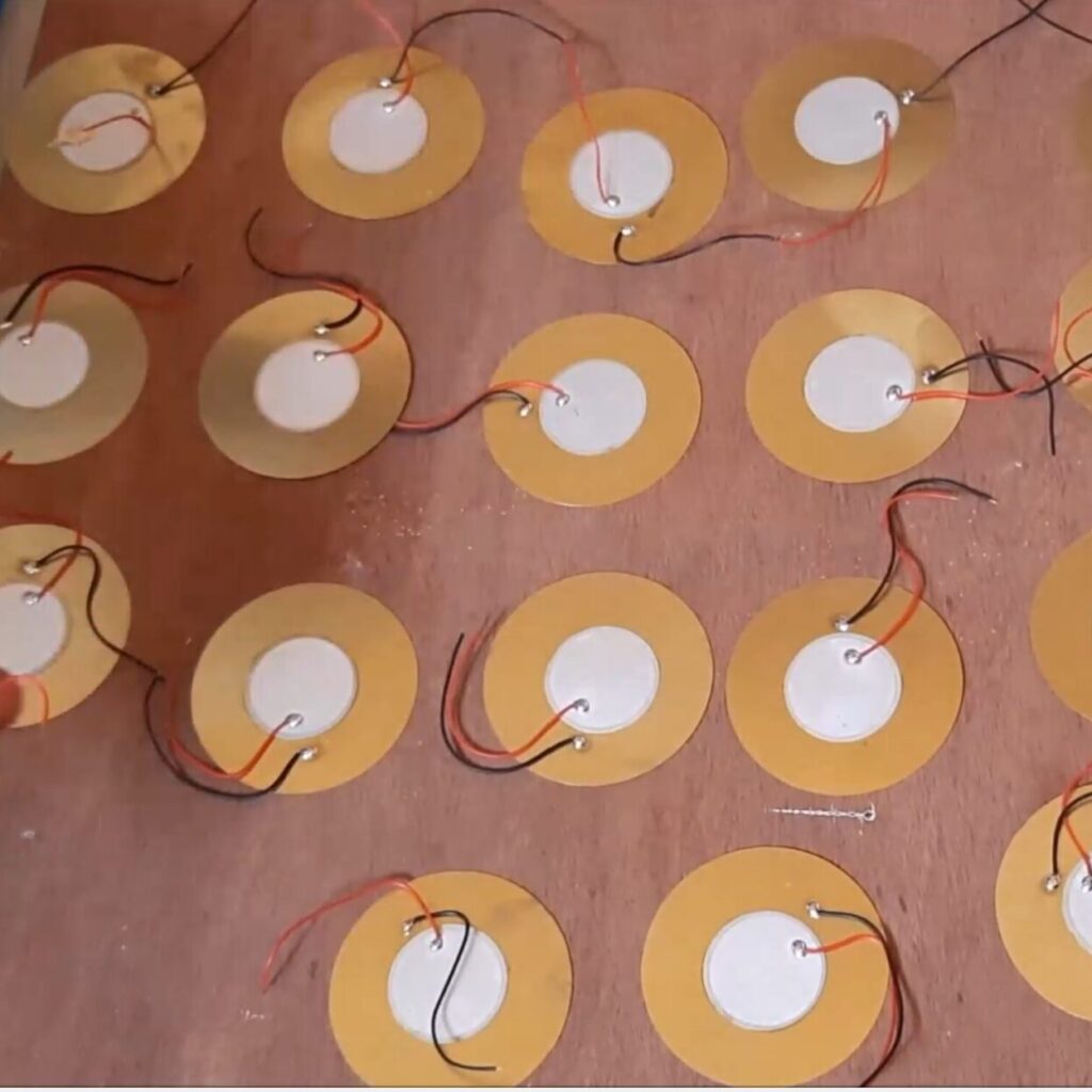
    PZT transducers are piezoelectric materials that generate electricity when subjected to mechanical stress. Commonly found in applications like sensors and actuators, these devices are ideal for harvesting small amounts of energy from movements like vibrations, pressure, or footsteps.

    • Compact and lightweight: Easy to integrate into compact designs.
    • Durable: Can withstand repeated mechanical stresses.
    • Eco-friendly: Generates clean energy with no emissions.

    Read Also: IoT-Based Early Warning Systems for Frost Detection in Orchards

    Components and Materials Required for This Project Design

    components used for the piezo-electric energy generator project design

    Here’s what you’ll need:

    • PZT transducers: Multiple units for harvesting energy.
    • ESP-01 module: A Wi-Fi-enabled microcontroller for IoT.
    • Arduino Mega board, the ch340 compact type
    • Rechargeable battery: To store the energy generated.
    • DC-DC buck converter: To buck down DC voltage
    • Voltage Regulator: To stabilize the output from PZT transducers.
    • LED lights: For the smart lighting component.
    • Resistors and capacitors: For circuit design.
    • Diodes: To prevent reverse current flow.
    • Breadboard and jumper wires: For prototyping.
    • Micro USB cable and adapter: For powering and programming the ESP-01.
    The components used for the IoT enabled energy generation project design

    The Arduino Mega board was the brain of the project design, we used the ESP-01 as another dev board that would send the values measured to the IoT platform. The relationship between these two dev boards are in the way they were connected using the the Serial Communication Protocol. The Arduino Mega board would send data to the ESP-01 and the ESP-01 would receive this data and using internet connectivity, send it to the Blynk cloud.

    Read Also: The History of Money: From Barter to Cryptocurrency

    Step 1: The Circuit Design: Understanding the Circuit Design

    The circuit diagram: Generate Electrical Energy from Footsteps

    Explanation of Circuit Diagram

    The above circuit diagram was designed in Fritzing and it shows the connection of the energy harvesting/generation part that is made up of the piezo-electric transducers (PZTs) section. The PZTs were connected both in parallel and in series connection to maximize output. The output voltage which in an A.C waveform was connected to the bridge rectifier to convert it to DC form.

    We used a resistor of suitable value to form a voltage regulator and a Zener diode to ensure that is achieved. We connected this to the backup battery. The output of the battery is connected to a DC-DC buck converter to regulate an output of stable 5V that was used to power the Microcontrollers (MCUs) and peripherals in the circuitry.

    The circuit diagram of the smart street light with the IoT based energy generation project design
    The circuit diagram of the smart street light with the IoT based energy generation project design

    The actuator load, the smart streetlight, has the connection as shown above, we did the connection by plugging into the connector socket making it plug and play.

    To harness energy and control it efficiently, the circuit comprises three main parts:

    1. Energy harvesting circuit:
      • Connect PZT transducers in parallel to maximize energy output.
      • Use a diode bridge rectifier to convert AC voltage from the PZTs to DC.
      • Add a capacitor to smooth the DC output if possible.
    2. Energy storage circuit:
      • Feed the smoothed DC voltage into a rechargeable battery.
      • Include a voltage regulator to ensure consistent output for the, Arduino Mega, ESP-01 and LED lights.
    3. IoT control circuit:
      • Connect the ESP-01 module to the battery.
      • Integrate the ESP-01 with LEDs for smart lighting functionality.

    Read Also: Embracing Imperfections: The Path to a Happier Life

    Step 2: Programming the Arduino Mega and ESP-01 Module

    snippet of the Arduino code that measure the voltage generated by the PZTs

    The Arduino Mega acts as the brain of this project. Here’s how to set it and the ESP-01 up alongside the Arduino IDE:

    1. Install the Arduino IDE:
      • Download and install the Arduino IDE.
      • Add the ESP8266 board to the IDE by going to File > Preferences and adding the appropriate URL in the “Additional Board Manager URLs” field.
    2. Write the code:
      • The Arduino Mega would will control the LEDs based on user commands sent via a smartphone app or web interface. Whereas the ESP-01 would be the bridge between the IoT platform and the Arduino Mega baord.
      • Use libraries like WiFi.h and blynk.h to handle connectivity and communication.
    // include the library code:
    #include <LiquidCrystal.h>
    #include <EEPROM.h>
    #include <BigCrystal.h>
    #include <BigFont.h>
    #include <SoftwareSerial.h>
     
    // initialize the library with the numbers of the interface pins
    LiquidCrystal lcd(9, 13, 22, 25, 27, 29);
    BigCrystal bigCrystal(&lcd);
     
    int volt;
    float voltage1;
     
    float low = 3.2;
    float full = 10.0;
    //for the ESP-01
    #define gpio0 18  //used for software serial
    #define gpio1 28
    #define gpio2 20  //used for software serial
    #define gpio3 30
    //the serial comm.
    SoftwareSerial arduino(gpio2, gpio0);
    //for LDR
    #define ldrPin A2
    //for pirSensor
    #define pirSensorPin 7
    //for the transistor
    #define transistorBase 11
     
    // Define analog input for battery
    #define ANALOG_IN_PIN A1
    // Floats for ADC voltage & Input voltage
    float adc_voltage = 0.0;
    float in_voltage = 0.0;
    // Floats for resistor values in divider (in ohms)
    float R1 = 32380.0;
    float R2 = 11760.0;
    // Float for Reference Voltage
    float ref_voltage = 5.0;
    // Integer for ADC value
    int adc_value = 0;
     
    //define parameters for piezo generator
    float R3 = 30000.0;
    float R4 = 7500.0;
    #define ANALOG_IN_PIN1 A0
    // Floats for ADC voltage & Input voltage
    float adc_voltage1 = 0.0;
    float in_voltage1 = 0.0;
    // Float for Reference Voltage
    float ref_voltage1 = 5.0;
    // Integer for ADC value
    int adc_value1 = 0;
    int readButton;
     
     
    void setup() {
      // set up the LCD's number of columns and rows:
      lcd.begin(20, 4);
      Serial.begin(9600);
      arduino.begin(115200);
      //declare the inputs and outputs
      pinMode(transistorBase, OUTPUT);
      pinMode(pirSensorPin, INPUT);
      pinMode(ldrPin, INPUT);
      pinMode(gpio1, INPUT);
      pinMode(gpio3, INPUT);
      //write a welcome msg on lcd
      lcd.setCursor(2, 0);
      lcd.print("...WELCOME...");
      lcd.setCursor(3, 1);
      lcd.print("MR. BUKOLA ");
      delay(3000);
      lcd.clear();
      lcd.setCursor(4, 0);
      lcd.print("FOOT-STEP");
      lcd.setCursor(2, 1);
      lcd.print("PIEZOELECTRIC");
      lcd.setCursor(3, 2);
      lcd.print(" GENERATOR");
      lcd.setCursor(3, 30);
      lcd.print("  PROJECT");
      delay(3000);
      lcd.clear();
      for (int x = 0; x < 16; x++) {
        lcd.setCursor(0, 0);
        lcd.print("Checking Battery  ");
        lcd.setCursor(x, 1);
        lcd.print("*");
        delay(200);
      }
      lcd.clear();
    }
     
    float readBatteryVoltage() {
      // Read the Analog Input
      adc_value = analogRead(ANALOG_IN_PIN);
     
      // Determine voltage at ADC input
      adc_voltage = (adc_value * ref_voltage) / 1024.0;
     
      // Calculate voltage at divider input
      in_voltage = adc_voltage * (R1 + R2) / R2;
     
      // Print results to Serial Monitor to 2 decimal places
      // Serial.print("Input Voltage = ");
      // Serial.println(in_voltage, 2);
      return in_voltage;
    }
     
    float readPiezoGenVoltage() {
      // Read the Analog Input
      adc_value1 = analogRead(ANALOG_IN_PIN1);
     
      // Determine voltage at ADC input
      adc_voltage1 = (adc_value1 * ref_voltage1) / 1024.0;
     
      // Calculate voltage at divider input
      in_voltage1 = adc_voltage1 * (R3 + R4) / R4;
     
      // Print results to Serial Monitor to 2 decimal places
      // Serial.print("Input Voltage = ");
      // Serial.println(in_voltage1, 2);
      return in_voltage1;
    }
     
    int readOnlineStreetlightButton() {
      readButton = digitalRead(gpio1);
      Serial.print("Online Control Button: ");
      Serial.println(readButton);
      return readButton;
    }
     
    int checkNightTime() {
      readOnlineStreetlightButton();
      int checkLDR = analogRead(ldrPin);
      int checkPir = digitalRead(pirSensorPin);
      if (readButton == 1) {
        if (checkLDR < 200) {
          analogWrite(transistorBase, 25);
          if (checkPir == 1) {
            analogWrite(transistorBase, 255);
          }
        } else {
          digitalWrite(transistorBase, LOW);
        }
      }
     
      else {
      Serial.println("remote control disabled");
      }
     
      Serial.print("LDR reading: ");
      Serial.print(checkLDR);
      Serial.print(" PIR reading: ");
      Serial.println(checkPir);
    }
     
    void displayBattVoltage() {
      readBatteryVoltage();
      float batPercent = map(in_voltage, 0.11, 4.2, 0.0, 100.0);
      // Serial.print(batPercent);
      // Serial.println();
      batPercent = constrain(batPercent, 0, 99);
      // buffer to hold the converted variable having a length that is +1 of the variable lentgh
      char buffer[5];
      itoa(batPercent, buffer, 10);
      //dtostrf (floatVar, minStringWidthIncDecimalPoint, numVarsAfterDecimal, charBuf)
      // char buffer[5];
      //  dtostrf (batPercent, 0, 1, buffer);
      bigCrystal.printBig(buffer, 0, 0);
      bigCrystal.print("%");
      int number_count = 1;
      int number_temp = int(batPercent);
      while (number_temp != 0) {
        number_count++;
        number_temp /= 10;
      }
      number_count -= 1;
      if (batPercent < 1) { number_count = 1; }
      lcd.setCursor(0 + (number_count * 4), 0);
      bigCrystal.print(in_voltage);
      bigCrystal.print("V  ");
      lcd.setCursor(1 + (number_count * 4), 1);
      lcd.print(" BAT   ");
     
     
      Serial.print("Bat3 Percent:  ");
      Serial.print(batPercent);
      Serial.print("%");
     
      Serial.print(" Batt Voltage: ");
      Serial.print(in_voltage);  //print the voltge
      Serial.print("V");
     
      Serial.print(" Batt analogRead: ");
      Serial.println(adc_value);
    }
     
     
    void displayPiezoGen() {
      readPiezoGenVoltage();
      int readPiezoPin = analogRead(A0);
      // buffer to hold the converted variable having a length that is +1 of the variable lentgh
      char buffer[5];
      itoa(in_voltage1, buffer, 10);
      bigCrystal.printBig(buffer, 0, 2);
      bigCrystal.print("V");
      int number_count = 1;
      int number_temp = int(in_voltage1);
      while (number_temp != 0) {
        number_count++;
        number_temp /= 10;
      }
      number_count -= 1;
      if (in_voltage1 < 1) { number_count = 1; }
      lcd.setCursor(0 + (number_count * 4), 2);
      bigCrystal.print("  Piezo    ");
      lcd.setCursor(1 + (number_count * 4), 3);
      lcd.print(" Gen     ");
      Serial.print("Piezo Pin: ");
      Serial.print(readPiezoPin);
      Serial.print(" Piezo Voltage: ");
      Serial.print(in_voltage1);  //print the voltge
      Serial.println("V");
    }
     
     
    void loop() {
      checkNightTime();
      displayBattVoltage();
      displayPiezoGen();
      //send to the ESP01 dev board via serial comm.
      arduino.print(in_voltage);
      arduino.print("A");
      arduino.print(in_voltage1);
      arduino.print("B");
      arduino.print("\n");
     
      delay(1000);
      Serial.println("\n");
    }
    
    1. Upload the code:
      • Connect the Arduino Mega to your computer using a USB cord.
      • Also, connect the ESP-01 to your computer using an adapter.
      • Select the appropriate board and port in the Arduino IDE.
      • Upload the codes respectively.
    #include &lt;SoftwareSerial.h>
    /*ESP-01 pins are GPIO, Tx is GPIO1 (here define as 1, code line 6),
    */
    #define rxPin 0 // GPIO0 is the pin next to the ESP-01 Rx pin. The Rx (GPIO3), the Tx (GPIO1)
    #define txPin 2 //GPIO2
    #define pumpVirtualPin 1
    #define pumpVirtualPin1 3
    
    SoftwareSerial nodeMCU(rxPin, txPin);
    #define BLYNK_TEMPLATE_ID "TMPL23r_9ngTn"
    #define BLYNK_TEMPLATE_NAME "Footstep IoT Project"
    #define BLYNK_AUTH_TOKEN "_lxtDgv0m1Ihzc6-w_003KNlfpa6usiX"
    
    /* Comment this out to disable prints and save space */
    #define BLYNK_PRINT Serial
    
    int Button, Button1;
    
    #include &lt;ESP8266WiFi.h>
    #include &lt;BlynkSimpleEsp8266.h>
    
    // Your WiFi credentials.
    // Set password to "" for open networks.
    char ssid[] = "Galaxy A51 917E";
    char pass[] = "tosin@345";
    
    BlynkTimer timer;
    
    char c;
    String dataIn;
    int8_t indexOfA, indexOfB,indexOfC, indexOfD;
    String data1, data2, data3, data4;
    
    BLYNK_WRITE(V2) {
      Button = param.asInt();
        if (Button==1){
          digitalWrite(pumpVirtualPin, HIGH);
        }
    else if(Button==0){
     digitalWrite(pumpVirtualPin, LOW);
        }
    }
    
    BLYNK_WRITE(V3) {
      Button1 = param.asInt();
        if (Button1==1){
          digitalWrite(pumpVirtualPin1, HIGH);
        }
    else if(Button==0){
     digitalWrite(pumpVirtualPin1, LOW);
        }
    }
    
    void setup(){
      // Debug console
      Serial.begin(115200);
      nodeMCU.begin(115200);
    
      pinMode(pumpVirtualPin, OUTPUT);
    
      Blynk.begin(BLYNK_AUTH_TOKEN, ssid, pass);
       // Setup a function to be called every second
      //timer.setInterval(1000L, parse_data);
    }
    
    void recvData(){
      while(nodeMCU.available() >0){
      c = nodeMCU.read();
     
       if( c == '\n'){
        break;
      }
    
      else{
        dataIn += c;
      }
    }
    
    if(c == '\n'){
      //Serial.println(c);
      parse_data();
    
      Serial.println("data 1= " + data1);
      Serial.println("data 2= " + data2);
      Serial.println("............................");
      
      c = 0;
      dataIn = "";
      }
    }
    
    void loop(){
      recvData();
    
      Blynk.run();
      timer.run();
       
    }
    
    void parse_data(){
      indexOfA = dataIn.indexOf("A");
      indexOfB = dataIn.indexOf("B");
     
    
      data1 = dataIn.substring(0, indexOfA);
      data2 = dataIn.substring(indexOfA+1, indexOfB);
    
      
       float ch1 = data1.toFloat();
       float ch2 = data2.toFloat();
    
        Blynk.virtualWrite(V0, ch1);
        Blynk.virtualWrite(V1, ch2);


    }


    Explanation of Arduino Code

    The provided Arduino code is designed to control a system that utilizes an ESP-01 module for IoT applications, specifically focusing on managing a pump based on user input from the Blynk platform. The code begins by including the necessary libraries and defining pin configurations for the ESP-01’s RX and TX pins, as well as virtual pins for controlling two pumps. It initializes a SoftwareSerial object for communication with the ESP-01 and sets up Blynk authentication details, including template ID and authentication token. The setup() function configures the serial communication, initializes the pump pins as outputs, and establishes a connection to the Blynk server using provided WiFi credentials.

    In the loop() function, the code continuously checks for incoming data from the ESP-01 module using the recvData() function. This function reads data until a newline character is detected, at which point it calls parse_data() to extract relevant information. The extracted data is then sent to Blynk’s virtual pins for monitoring. Additionally, two Blynk write functions (BLYNK_WRITE) are defined to handle button presses from the Blynk app, allowing users to turn the pumps on or off based on their input. Overall, this code enables remote control of pumps through an Internet connection while providing real-time feedback on their status via the Blynk application.

    Read Also: How Long Would It Take a Hacker to Brute Force Your Password?

    Step 3: Assembling the Hardware

    Now, it’s time to bring everything together:

    The project design
    1. Energy harvesting module:
      • Mount the PZT transducers on a surface that experiences regular vibrations ( a staircase or floor).
      • Connect the output to the diode bridge rectifier.
    2. Energy storage module:
      • Attach the rectified output to the rechargeable battery via the voltage regulator.
    3. IoT module:
      • Connect the Arduino to the battery and LEDs.
      • Test connectivity and ensure the ESP-01 can send signals to the Arduino that can control the LEDs.

    Step 4: Testing and Calibration

    Testing the IoT Energy generation project design
    1. Test energy generation:
      • Apply mechanical stress to the PZT transducers and measure the voltage output.
      • Verify that the rectified voltage is sufficient to charge the battery.
    2. Test IoT functionality:
      • Access the ESP-01’s web interface using a smartphone or laptop.
      • Send commands, by toggling the online button on to turn the LEDs on and off turn it off.
    3. Fine-tune placement:
      • Adjust the placement of PZT transducers for optimal energy generation.

    Real-Life Applications

    This project demonstrates a scalable approach to renewable energy and smart technology. Potential applications include:

    • Smart homes: Motion-powered lighting for hallways and staircases.
    • Public spaces: Energy-harvesting tiles for streetlights.
    • Wearables: Powering sensors using body movements.

    Challenges and Troubleshooting Tips

    1. Low energy output:
      • Combine multiple PZT transducers.
      • Use high-efficiency voltage regulators.
    2. ESP-01 connectivity issues:
      • Check Wi-Fi credentials and signal strength.
      • Reflash the firmware if necessary.
    3. LED flickering:
      • Add capacitors to smooth the power supply.

    Environmental Benefits

    By harnessing renewable energy and using IoT for smart control, this project reduces reliance on traditional energy sources. It’s a small step toward a sustainable future.

    Conclusion

    This DIY project combines the innovative concepts of IoT, energy harvesting, and smart lighting to create a practical and sustainable solution, an IoT-Enabled Energy Generation and Smart Lighting. Whether you’re a hobbyist or a professional, this project is an excellent way to explore the potential of piezoelectric transducers and IoT technology. Why not give it a try and make your home a little smarter while contributing to a greener planet?

    FAQs

    1. Can I use other microcontrollers instead of Arduino Mega and ESP-01?
    Yes, you can use other microcontrollers like ESP32, Arduino Uno with a Wi-Fi shield, or NodeMCU for added flexibility and features.

    2. How much energy can a PZT transducer generate?
    The energy output depends on the size and quality of the PZT transducer, but typically it ranges from micro-watts to milliwatts.

    3. Is this project suitable for beginners?
    Yes, with basic knowledge of electronics and programming, beginners can successfully complete this project.

    4. Can I expand this project to power more devices?
    Yes, by adding more PZT transducers and larger storage components, you can scale up the system to power additional devices.

    5. What apps can I use to control the ESP-01?
    You can use web browsers, Blynk, or custom IoT apps to send commands to the ESP-01.

  • How to Generate Electrical Energy with Footsteps Arduino

    How to Generate Electrical Energy with Footsteps Arduino

    In a world that is increasingly focused on sustainability and renewable energy, innovative solutions are emerging that harness everyday actions to generate electricity. One such remarkable innovation is the use of piezoelectric transducers (PZT) to convert the mechanical energy from footsteps into electrical energy. This article explores the fascinating project of generating electrical energy with footsteps using Arduino, detailing the components, functionality, and potential applications of this technology.

    What Are Piezoelectric Transducers?

    How to Generate Electrical Energy with Footsteps with Arduino
    How to Generate Electrical Energy with Footsteps with Arduino

    Piezoelectric transducers are devices that convert mechanical stress into electrical energy. The piezoelectric effect occurs in certain materials when they are subjected to pressure or deformation, resulting in an electric charge. This phenomenon is utilized in various applications, from sensors to energy harvesting devices.

    Read Also: Digital Temperature Monitor Using LM35 Sensor and Arduino

    How Do Piezoelectric Transducers Work?

    The working principle of PZTs

    When a piezoelectric material is compressed or stretched, it generates an electrical voltage across its terminals. This voltage can be harnessed and used to power electronic devices or charge batteries. The efficiency of this process depends on the type of piezoelectric material used and the design of the transducer.

    Read Also: How to build a Motorized Curtain System using DC Motor, Push Buttons, and Arduino Uno

    Project Overview: Generating Energy with Footsteps

    How to Generate Electrical Energy with Footsteps Arduino
    How to Generate Electrical Energy with Footsteps Arduino

    The project titled “How to Generate Electrical Energy with Footsteps Arduino” involves assembling piezoelectric transducers in a way that they produce voltage when stepped on. The setup includes an Arduino Mega microcontroller to read the voltage output, an LCD for display, and a rechargeable battery for storage.

    Read Also: IoT Smart Doorbell With Email Alert, Video Stream, Arduino and Blynk

    Components Used

    components used for the piezo-electric energy generator project design
    1. Piezoelectric Transducers (PZT): These are the core components that convert mechanical energy from footsteps into electrical energy.
    2. Arduino Mega (CH340 Compact Type): This microcontroller reads the voltage output from the PZTs and controls other components.
    3. LCD Display: Used to show the voltage output in volts and percentage.
    4. Rechargeable Battery (4.2V 3800mAh LiPo): Stores the generated energy for later use.
    5. 12V DC Bulb: Acts as a load to demonstrate the practical application of the generated energy.
    6. LDR (Light Dependent Resistor): Senses ambient light levels to control the street light operation.
    7. PIR Sensor: Increases light intensity when motion is detected.
    8. ESP-01 Module: Sends data to an IoT platform for remote monitoring and control.

    The Schematic Diagram: Setting Up the System

    The circuit diagram: Generate Electrical Energy from Footsteps

    Explanation of the Schematic Diagram

    The schematic diagram shows the connection of the piezo-electric transducers (PZTs) in the PZT generator design. We did both parallel and series connection for the PZTs. This was targeted to increase the A.C voltage output.

    Steps involved in Assembling and Coupling The Piezo-electric Generator (Generate Electrical Energy with Footsteps Using Arduino)

    Step 1: Assembling Piezoelectric Transducers

    The first step in this project involves arranging multiple piezoelectric transducers under a surface where people will walk. The arrangement should ensure that each step applies pressure evenly across the transducers, maximizing energy generation.

    Read More: How to Build An Over-Speeding Limit Project Arduino

    Step 2: Programming and Connecting to Arduino

    // include the library code:
    #include <LiquidCrystal.h>
    #include <EEPROM.h>
    #include <BigCrystal.h>
    #include <BigFont.h>
    #include <SoftwareSerial.h>
     
    // initialize the library with the numbers of the interface pins
    LiquidCrystal lcd(9, 13, 22, 25, 27, 29);
    BigCrystal bigCrystal(&lcd);
     
    int volt;
    float voltage1;
     
    float low = 3.2;
    float full = 10.0;
    //for the ESP-01
    #define gpio0 18  //used for software serial
    #define gpio1 28
    #define gpio2 20  //used for software serial
    #define gpio3 30
    //the serial comm.
    SoftwareSerial arduino(gpio2, gpio0);
    //for LDR
    #define ldrPin A2
    //for pirSensor
    #define pirSensorPin 7
    //for the transistor
    #define transistorBase 11
     
    // Define analog input for battery
    #define ANALOG_IN_PIN A1
    // Floats for ADC voltage & Input voltage
    float adc_voltage = 0.0;
    float in_voltage = 0.0;
    // Floats for resistor values in divider (in ohms)
    float R1 = 32380.0;
    float R2 = 11760.0;
    // Float for Reference Voltage
    float ref_voltage = 5.0;
    // Integer for ADC value
    int adc_value = 0;
     
    //define parameters for piezo generator
    float R3 = 30000.0;
    float R4 = 7500.0;
    #define ANALOG_IN_PIN1 A0
    // Floats for ADC voltage & Input voltage
    float adc_voltage1 = 0.0;
    float in_voltage1 = 0.0;
    // Float for Reference Voltage
    float ref_voltage1 = 5.0;
    // Integer for ADC value
    int adc_value1 = 0;
    int readButton;
     
     
    void setup() {
      // set up the LCD's number of columns and rows:
      lcd.begin(20, 4);
      Serial.begin(9600);
      arduino.begin(115200);
      //declare the inputs and outputs
      pinMode(transistorBase, OUTPUT);
      pinMode(pirSensorPin, INPUT);
      pinMode(ldrPin, INPUT);
      pinMode(gpio1, INPUT);
      pinMode(gpio3, INPUT);
      //write a welcome msg on lcd
      lcd.setCursor(2, 0);
      lcd.print("...WELCOME...");
      lcd.setCursor(3, 1);
      lcd.print("MR. BUKOLA ");
      delay(3000);
      lcd.clear();
      lcd.setCursor(4, 0);
      lcd.print("FOOT-STEP");
      lcd.setCursor(2, 1);
      lcd.print("PIEZOELECTRIC");
      lcd.setCursor(3, 2);
      lcd.print(" GENERATOR");
      lcd.setCursor(3, 30);
      lcd.print("  PROJECT");
      delay(3000);
      lcd.clear();
      for (int x = 0; x < 16; x++) {
        lcd.setCursor(0, 0);
        lcd.print("Checking Battery  ");
        lcd.setCursor(x, 1);
        lcd.print("*");
        delay(200);
      }
      lcd.clear();
    }
     
    float readBatteryVoltage() {
      // Read the Analog Input
      adc_value = analogRead(ANALOG_IN_PIN);
     
      // Determine voltage at ADC input
      adc_voltage = (adc_value * ref_voltage) / 1024.0;
     
      // Calculate voltage at divider input
      in_voltage = adc_voltage * (R1 + R2) / R2;
     
      // Print results to Serial Monitor to 2 decimal places
      // Serial.print("Input Voltage = ");
      // Serial.println(in_voltage, 2);
      return in_voltage;
    }
     
    float readPiezoGenVoltage() {
      // Read the Analog Input
      adc_value1 = analogRead(ANALOG_IN_PIN1);
     
      // Determine voltage at ADC input
      adc_voltage1 = (adc_value1 * ref_voltage1) / 1024.0;
     
      // Calculate voltage at divider input
      in_voltage1 = adc_voltage1 * (R3 + R4) / R4;
     
      // Print results to Serial Monitor to 2 decimal places
      // Serial.print("Input Voltage = ");
      // Serial.println(in_voltage1, 2);
      return in_voltage1;
    }
     
    int readOnlineStreetlightButton() {
      readButton = digitalRead(gpio1);
      Serial.print("Online Control Button: ");
      Serial.println(readButton);
      return readButton;
    }
     
    int checkNightTime() {
      readOnlineStreetlightButton();
      int checkLDR = analogRead(ldrPin);
      int checkPir = digitalRead(pirSensorPin);
      if (readButton == 1) {
        if (checkLDR < 200) {
          analogWrite(transistorBase, 25);
          if (checkPir == 1) {
            analogWrite(transistorBase, 255);
          }
        } else {
          digitalWrite(transistorBase, LOW);
        }
      }
     
      else {
      Serial.println("remote control disabled");
      }
     
      Serial.print("LDR reading: ");
      Serial.print(checkLDR);
      Serial.print(" PIR reading: ");
      Serial.println(checkPir);
    }
     
    void displayBattVoltage() {
      readBatteryVoltage();
      float batPercent = map(in_voltage, 0.11, 4.2, 0.0, 100.0);
      // Serial.print(batPercent);
      // Serial.println();
      batPercent = constrain(batPercent, 0, 99);
      // buffer to hold the converted variable having a length that is +1 of the variable lentgh
      char buffer[5];
      itoa(batPercent, buffer, 10);
      //dtostrf (floatVar, minStringWidthIncDecimalPoint, numVarsAfterDecimal, charBuf)
      // char buffer[5];
      //  dtostrf (batPercent, 0, 1, buffer);
      bigCrystal.printBig(buffer, 0, 0);
      bigCrystal.print("%");
      int number_count = 1;
      int number_temp = int(batPercent);
      while (number_temp != 0) {
        number_count++;
        number_temp /= 10;
      }
      number_count -= 1;
      if (batPercent < 1) { number_count = 1; }
      lcd.setCursor(0 + (number_count * 4), 0);
      bigCrystal.print(in_voltage);
      bigCrystal.print("V  ");
      lcd.setCursor(1 + (number_count * 4), 1);
      lcd.print(" BAT   ");
     
     
      Serial.print("Bat3 Percent:  ");
      Serial.print(batPercent);
      Serial.print("%");
     
      Serial.print(" Batt Voltage: ");
      Serial.print(in_voltage);  //print the voltge
      Serial.print("V");
     
      Serial.print(" Batt analogRead: ");
      Serial.println(adc_value);
    }
     
     
    void displayPiezoGen() {
      readPiezoGenVoltage();
      int readPiezoPin = analogRead(A0);
      // buffer to hold the converted variable having a length that is +1 of the variable lentgh
      char buffer[5];
      itoa(in_voltage1, buffer, 10);
      bigCrystal.printBig(buffer, 0, 2);
      bigCrystal.print("V");
      int number_count = 1;
      int number_temp = int(in_voltage1);
      while (number_temp != 0) {
        number_count++;
        number_temp /= 10;
      }
      number_count -= 1;
      if (in_voltage1 < 1) { number_count = 1; }
      lcd.setCursor(0 + (number_count * 4), 2);
      bigCrystal.print("  Piezo    ");
      lcd.setCursor(1 + (number_count * 4), 3);
      lcd.print(" Gen     ");
      Serial.print("Piezo Pin: ");
      Serial.print(readPiezoPin);
      Serial.print(" Piezo Voltage: ");
      Serial.print(in_voltage1);  //print the voltge
      Serial.println("V");
    }
     
     
    void loop() {
      checkNightTime();
      displayBattVoltage();
      displayPiezoGen();
      //send to the ESP01 dev board via serial comm.
      arduino.print(in_voltage);
      arduino.print("A");
      arduino.print(in_voltage1);
      arduino.print("B");
      arduino.print("\n");
     
      delay(1000);
      Serial.println("\n");
    }
    

    The voltage output from each piezoelectric transducer needs to be connected to the analog input pins of the Arduino Mega. This allows the microcontroller to read the voltage levels generated by foot traffic. The above code does the whole work, just connect your Arduino and upload the code.

    Step 3: Displaying Voltage Output

    displaying the voltage generated on an LCD screen

    Using an LCD display connected to the Arduino, you can visualize the voltage readings in real-time. This provides immediate feedback on how much energy is being generated with each step.

    Step 4: Storing Energy

    The project design

    The generated electricity can be used to charge a rechargeable battery, ensuring that there is always a backup power source available for when foot traffic is low. The LiPo battery chosen for this project has a capacity of 3800mAh, making it suitable for storing significant amounts of energy.

    Smart Street Light Integration

    One of the innovative aspects of this project is its integration with smart street lighting technology.

    Using LDRs for Day/Night Detection

    The LDR detects ambient light levels and controls whether the street light should be on or off based on whether it is day or night. This automation helps conserve energy by ensuring that lights are only on when needed.

    Enhancing Luminosity with PIR Sensors

    The PIR sensor plays a crucial role in enhancing safety and visibility at night by increasing luminosity when motion is detected nearby. This feature not only saves energy but also ensures that pedestrians feel safer when walking through illuminated areas.

    IoT Integration with ESP-01

    To take this project a step further, integrating an ESP-01 module allows for remote monitoring and control via an IoT platform like Blynk.

    Sending Data to IoT Platform

    The Blynk IoT platform where the readings are sent

    The ESP-01 can send real-time data regarding:

    • Generated voltage from PZTs
    • Battery charge status
    • State of the street light (on/off)

    This data can be accessed remotely, allowing users to monitor their system’s performance from anywhere.

    Remote Control Functionality

    With a user-friendly interface on the IoT platform, you can turn your smart street light on or off at will. This feature adds convenience and flexibility, enabling users to manage their lighting system effectively.

    Testing The Project Design: Results and Analysis

    The results obtained from Generating Energy with Footsteps

    The result of the project design here shows the voltage generated as it is being stepped on. Also the voltage of the backup battery.

    Benefits of Generating Energy with Footsteps

    Sustainability

    Harnessing energy from footsteps contributes to sustainable practices by utilizing renewable resources—our daily movements—to generate power without depleting natural resources.

    Cost-Effectiveness

    This system reduces reliance on traditional power sources, potentially lowering electricity bills and maintenance costs associated with conventional street lighting systems.

    Innovative Applications

    Beyond street lighting, this technology can be applied in various settings such as:

    • Public transportation hubs
    • Shopping malls
    • Parks and recreational areas
    • Smart cities initiatives

    Challenges and Considerations

    While this project showcases exciting possibilities, there are challenges to consider:

    Efficiency of Energy Conversion

    The efficiency of piezoelectric transducers can vary based on design and material properties. It’s essential to choose high-quality PZTs for optimal performance.

    Maintenance Requirements

    Regular maintenance may be required to ensure that all components function correctly over time, especially in outdoor environments where exposure to elements can affect performance.

    Future Prospects

    As technology advances, we may see improvements in piezoelectric materials that enhance their efficiency and durability. Research into lead-free alternatives also presents exciting opportunities for environmentally friendly solutions.

    Conclusion

    The project “How to Generate Electrical Energy with Footsteps Arduino” exemplifies how innovative thinking can lead to sustainable solutions for everyday challenges. By harnessing mechanical energy from footsteps through piezoelectric transducers, we can create systems that not only generate electricity but also contribute positively to our environment. As we continue exploring renewable energy sources, projects like these pave the way toward smarter cities and more sustainable living practices.

    FAQs

    What are piezoelectric transducers?

    • Piezoelectric transducers convert mechanical stress into electrical energy through the piezoelectric effect found in certain materials.

    How does an Arduino read voltage from PZT?

    • An Arduino reads voltage by connecting its analog input pins to the output terminals of piezoelectric transducers, allowing it to measure generated voltage levels.

    Can I use this system indoors?

    • Yes! While designed for outdoor applications like street lighting, this system can also be implemented indoors in high foot traffic areas like malls or airports.

    What type of battery is used in this project?

    • A 4.2V 3800mAh LiPo rechargeable battery is used for storing generated energy as backup power.

    How does IoT integration enhance this project?

    • IoT integration allows remote monitoring and control of systems via platforms like Zafron, providing real-time data on voltage generation and enabling users to manage street lights effectively from anywhere.
  • DIY Smart Streetlight Powered by Footstep Energy | Arduino & ESP-01 Explained!

    DIY Smart Streetlight Powered by Footstep Energy | Arduino & ESP-01 Explained!

    In a world where renewable energy and smart technology are taking center stage, combining these two innovations into a DIY project is both fascinating and practical. Imagine a streetlight powered by footsteps – harnessing human energy to light up the night while sending data to an IoT platform for real-time monitoring. Sounds exciting? Let’s dive into how you can build this cutting-edge project, a DIY Smart Streetlight Powered by Footstep Energy.

    What Is a Smart Streetlight Powered by Footstep Energy?

    Smart Streetlight Powered by Footstep Energy

    A smart streetlight powered by footstep energy is a sustainable lighting system that uses energy generated from footfalls to charge a battery, which powers the streetlight. It combines motion detection, light-sensing capabilities, and IoT integration to create a highly efficient and futuristic lighting solution.

    Rad Also: How to Start a Blog in 10 Easy Steps for Money

    How Does It Work?

    The piezo-electric transducers used for this project design

    This project relies on three main components:

    1. Footstep Energy Generator: Converts kinetic energy from footsteps into electrical energy.
    2. Arduino Microcontroller: Acts as the brain of the system, controlling the motion sensor, LDR, and ESP-01 module.
    3. ESP-01 Module: Sends real-time data about the battery voltage and charging status to an IoT platform.
    Arduino mega and ESP-01 module for the Smart Streetlight Powered by Footstep Energy
    Arduino mega and ESP-01 module for the Smart Streetlight Powered by Footstep Energy

    These components are very vital for the project design itself. We used the ESP-01 module to give the design an internet access to communicate with the IoT platform.

    Read Also: How to Make Money on TikTok: Your Ultimate Guide

    Key Features of the DIY Smart Streetlight

    1. Motion-Activated Brightness: A motion sensor ensures the light only brightens when someone is nearby, conserving energy.
    2. Day/Night Detection: An LDR (Light Dependent Resistor) detects ambient light levels, activating the streetlight only at night.
    3. IoT Monitoring: The ESP-01 module uploads battery voltage and charging status to an IoT platform for remote monitoring.
    4. Renewable Energy Source: A footstep energy generator charges the battery, reducing dependency on traditional power sources.

    Components Required

    PIR Motion Sensor used in the Smart Streetlight Powered by Footstep Energy project design
    PIR Motion Sensor used in the Smart Streetlight Powered by Footstep Energy project design

    Before you start building, gather the following components:

    Core Electronics

    • Arduino Mega (or any compatible microcontroller)
    • ESP-01 Wi-Fi Module
    • PIR Motion Sensor
    • LDR (Light Dependent Resistor)
    • Rechargeable Battery (12V recommended)
    • Battery Charging Circuit
    • Footstep Energy Generator

    Additional Components

    • Resistors (1kΩ, 10kΩ)
    • Capacitors
    • Diodes (1N4007 or similar)
    • Voltage Regulator (e.g., LM7805)
    • LED red and green
    • Connecting Wires
    • Veroboard or PCB

    Read Also: How to Cope with Breakups: Moving On After a Relationship Ends

    Step-by-Step Guide to Building the Smart Streetlight

    Step 1: Setting Up the Footstep Energy Generator

    The piezo-electric transducers used for this project design

    The footstep energy generator is a piezoelectric system that generates electricity when pressure is applied. The first thing we do is to assemble and align the PZT materials on a flat wood, this is done judiciously. After carefully placing these transducers on the flat board, we can move onto the next step. While in the process of laying down the PZT sensors, we have to align them in a way it will be most convenient to connect them in a series connection as shown in the schematic diagram. Once we have achieved this structural outline, we can then start joining the polarities of the PZT in both serial and parallel connect following the circuit diagram. To ensure that the connection is firm and tight, we had to solder the PZTs together where their polarities of their terminals were join. However before this soldering process, we used a glue gun to glue the PZT sensors onto the flat board so that it can be helping in place for the terminal joint and soldering.

    Follow these steps:

    1. Arrange multiple piezoelectric discs under a durable platform.
    2. Connect the discs in parallel to a rectifier circuit.
    3. Use a capacitor to smooth out the voltage output.
    4. Connect the output to a rechargeable battery through a charging circuit.

    Step 2: Assembling the Arduino Circuit for the DIY smart streetlight

    circuit diagram for smart street light project design
    circuit diagram for smart street light project design
    1. Connect the PIR motion sensor to the Arduino. The sensor’s output pin goes to one of the Arduino’s digital input pins, D9.
    2. Connect the LDR to an analog input pin using a voltage divider circuit.
    3. Attach the LED light module to a digital output pin, using a transistor if needed for higher current loads.
    4. Integrate the ESP-01 module with the Arduino through UART communication (TX and RX pins).

    Step 3: Programming the Arduino

    Here is the Arduino code

    // include the library code:
    #include <LiquidCrystal.h>
    #include <EEPROM.h>
    #include <BigCrystal.h>
    #include <BigFont.h>
    #include <SoftwareSerial.h>
    
    // initialize the library with the numbers of the interface pins
    LiquidCrystal lcd(9, 13, 22, 25, 27, 29);
    BigCrystal bigCrystal(&lcd);
    
    int volt;
    float voltage1;
    
    float low = 3.2;
    float full = 10.0;
    //for the ESP-01
    #define gpio0 18  //used for software serial
    #define gpio1 28
    #define gpio2 20  //used for software serial
    #define gpio3 30
    //the serial comm.
    SoftwareSerial arduino(gpio2, gpio0);
    //for LDR
    #define ldrPin A2
    //for pirSensor
    #define pirSensorPin 7
    //for the transistor
    #define transistorBase 11
    
    // Define analog input for battery
    #define ANALOG_IN_PIN A1
    // Floats for ADC voltage & Input voltage
    float adc_voltage = 0.0;
    float in_voltage = 0.0;
    // Floats for resistor values in divider (in ohms)
    float R1 = 32380.0;
    float R2 = 11760.0;
    // Float for Reference Voltage
    float ref_voltage = 5.0;
    // Integer for ADC value
    int adc_value = 0;
    
    //define parameters for piezo generator
    float R3 = 30000.0;
    float R4 = 7500.0;
    #define ANALOG_IN_PIN1 A0
    // Floats for ADC voltage & Input voltage
    float adc_voltage1 = 0.0;
    float in_voltage1 = 0.0;
    // Float for Reference Voltage
    float ref_voltage1 = 5.0;
    // Integer for ADC value
    int adc_value1 = 0;
    int readButton;
    
    
    void setup() {
      // set up the LCD's number of columns and rows:
      lcd.begin(20, 4);
      Serial.begin(9600);
      arduino.begin(115200);
      //declare the inputs and outputs
      pinMode(transistorBase, OUTPUT);
      pinMode(pirSensorPin, INPUT);
      pinMode(ldrPin, INPUT);
      pinMode(gpio1, INPUT);
      pinMode(gpio3, INPUT);
      //write a welcome msg on lcd
      lcd.setCursor(2, 0);
      lcd.print("...WELCOME...");
      lcd.setCursor(3, 1);
      lcd.print("MR. BUKOLA ");
      delay(3000);
      lcd.clear();
      lcd.setCursor(4, 0);
      lcd.print("FOOT-STEP");
      lcd.setCursor(2, 1);
      lcd.print("PIEZOELECTRIC");
      lcd.setCursor(3, 2);
      lcd.print(" GENERATOR");
      lcd.setCursor(3, 30);
      lcd.print("  PROJECT");
      delay(3000);
      lcd.clear();
      for (int x = 0; x < 16; x++) {
        lcd.setCursor(0, 0);
        lcd.print("Checking Battery  ");
        lcd.setCursor(x, 1);
        lcd.print("*");
        delay(200);
      }
      lcd.clear();
    }
    
    float readBatteryVoltage() {
      // Read the Analog Input
      adc_value = analogRead(ANALOG_IN_PIN);
    
      // Determine voltage at ADC input
      adc_voltage = (adc_value * ref_voltage) / 1024.0;
    
      // Calculate voltage at divider input
      in_voltage = adc_voltage * (R1 + R2) / R2;
    
      // Print results to Serial Monitor to 2 decimal places
      // Serial.print("Input Voltage = ");
      // Serial.println(in_voltage, 2);
      return in_voltage;
    }
    
    float readPiezoGenVoltage() {
      // Read the Analog Input
      adc_value1 = analogRead(ANALOG_IN_PIN1);
    
      // Determine voltage at ADC input
      adc_voltage1 = (adc_value1 * ref_voltage1) / 1024.0;
    
      // Calculate voltage at divider input
      in_voltage1 = adc_voltage1 * (R3 + R4) / R4;
    
      // Print results to Serial Monitor to 2 decimal places
      // Serial.print("Input Voltage = ");
      // Serial.println(in_voltage1, 2);
      return in_voltage1;
    }
    
    int readOnlineStreetlightButton() {
      readButton = digitalRead(gpio1);
      Serial.print("Online Control Button: ");
      Serial.println(readButton);
      return readButton;
    }
    
    int checkNightTime() {
      readOnlineStreetlightButton();
      int checkLDR = analogRead(ldrPin);
      int checkPir = digitalRead(pirSensorPin);
      if (readButton == 1) {
        if (checkLDR < 200) {
          analogWrite(transistorBase, 25);
          if (checkPir == 1) {
            analogWrite(transistorBase, 255);
          }
        } else {
          digitalWrite(transistorBase, LOW);
        }
      }
    
      else {
      Serial.println("remote control disabled");
      }
    
      Serial.print("LDR reading: ");
      Serial.print(checkLDR);
      Serial.print(" PIR reading: ");
      Serial.println(checkPir);
    }
    
    void displayBattVoltage() {
      readBatteryVoltage();
      float batPercent = map(in_voltage, 0.11, 4.2, 0.0, 100.0);
      // Serial.print(batPercent);
      // Serial.println();
      batPercent = constrain(batPercent, 0, 99);
      // buffer to hold the converted variable having a length that is +1 of the variable lentgh
      char buffer[5];
      itoa(batPercent, buffer, 10);
      //dtostrf (floatVar, minStringWidthIncDecimalPoint, numVarsAfterDecimal, charBuf)
      // char buffer[5];
      //  dtostrf (batPercent, 0, 1, buffer);
      bigCrystal.printBig(buffer, 0, 0);
      bigCrystal.print("%");
      int number_count = 1;
      int number_temp = int(batPercent);
      while (number_temp != 0) {
        number_count++;
        number_temp /= 10;
      }
      number_count -= 1;
      if (batPercent < 1) { number_count = 1; }
      lcd.setCursor(0 + (number_count * 4), 0);
      bigCrystal.print(in_voltage);
      bigCrystal.print("V  ");
      lcd.setCursor(1 + (number_count * 4), 1);
      lcd.print(" BAT   ");
    
    
      Serial.print("Bat3 Percent:  ");
      Serial.print(batPercent);
      Serial.print("%");
    
      Serial.print(" Batt Voltage: ");
      Serial.print(in_voltage);  //print the voltge
      Serial.print("V");
    
      Serial.print(" Batt analogRead: ");
      Serial.println(adc_value);
    }
    
    
    void displayPiezoGen() {
      readPiezoGenVoltage();
      int readPiezoPin = analogRead(A0);
      // buffer to hold the converted variable having a length that is +1 of the variable lentgh
      char buffer[5];
      itoa(in_voltage1, buffer, 10);
      bigCrystal.printBig(buffer, 0, 2);
      bigCrystal.print("V");
      int number_count = 1;
      int number_temp = int(in_voltage1);
      while (number_temp != 0) {
        number_count++;
        number_temp /= 10;
      }
      number_count -= 1;
      if (in_voltage1 < 1) { number_count = 1; }
      lcd.setCursor(0 + (number_count * 4), 2);
      bigCrystal.print("  Piezo    ");
      lcd.setCursor(1 + (number_count * 4), 3);
      lcd.print(" Gen     ");
      Serial.print("Piezo Pin: ");
      Serial.print(readPiezoPin);
      Serial.print(" Piezo Voltage: ");
      Serial.print(in_voltage1);  //print the voltge
      Serial.println("V");
    }
    
    
    void loop() {
      checkNightTime();
      displayBattVoltage();
      displayPiezoGen();
      //send to the ESP01 dev board via serial comm.
      arduino.print(in_voltage);
      arduino.print("A");
      arduino.print(in_voltage1);
      arduino.print("B");
      arduino.print("\n");
    
      delay(1000);
      Serial.println("\n");
    }


    Explanation of Arduino Code

    • The Arduino code reads motion data from the PIR sensor.
    • Checks ambient light levels using the LDR.
    • Activates the LED when motion is detected and it’s dark.
    • Sends battery voltage and charging status data to the ESP-01 module.

    Step 4: Configuring the ESP-01 Module

    1. Flash the ESP-01 with firmware compatible with your IoT platform (e.g., Blynk or ThingSpeak).
    2. Use AT commands to connect the module to your Wi-Fi network.
    3. Configure the ESP-01 to upload battery data and charging voltage to your chosen IoT platform.

    Step 5: Testing and Troubleshooting

    1. Walk over the footstep generator to charge the battery.
    2. Ensure the streetlight turns on only when motion is detected and it’s dark.
    3. Check if the ESP-01 uploads real-time data accurately.

    Applications of the Smart Streetlight

    1. Public Pathways: Illuminate walkways using human energy.
    2. Campus Lighting: Use the system in schools and universities to promote sustainability.
    3. Remote Areas: Implement in areas without access to the power grid.
    4. Sports Arenas: Install in stadiums to harness the energy of large crowds.

    Benefits of the Project

    • Cost Efficiency: Reduces electricity bills.
    • Environmentally Friendly: Promotes renewable energy.
    • IoT Integration: Provides data for monitoring and optimization.
    • Scalability: Can be adapted for larger systems.

    Potential Improvements

    1. Enhanced Energy Storage: Use higher-capacity batteries.
    2. Advanced Sensors: Integrate ultrasonic sensors for better motion detection.
    3. Solar Backup: Combine footstep energy with solar panels for continuous power.
    4. Advanced Analytics: Use AI to analyze energy usage and optimize performance.

    Conclusion

    Building a DIY smart streetlight powered by footstep energy is not only a fun and educational project but also a meaningful step toward sustainability. With its combination of renewable energy, smart technology, and IoT integration, this project has the potential to revolutionize how we think about public lighting.

    So why wait? Gather your components, follow the steps, and start building your own smart streetlight today!

    FAQs

    1. Can I use a different microcontroller instead of Arduino?

    Yes, you can use other microcontrollers like ESP32 or Raspberry Pi, but you’ll need to adapt the code and connections accordingly.

    2. How much energy can the footstep generator produce?

    The energy output depends on the number and type of piezoelectric discs used. Typically, it’s enough to charge small batteries for low-power devices.

    3. What IoT platforms can I use for this project?

    Popular options include Blynk, ThingSpeak, and Adafruit IO.

    4. Is the system weatherproof?

    You’ll need to encase the components in waterproof housing for outdoor use.

    5. Can I add more sensors to the system?

    Absolutely! You can add temperature, humidity, or air quality sensors for additional functionality.