Introduction
The Internet of Things (IoT) has revolutionized how we interact with everyday devices, making our homes smarter and our lives more efficient. One fascinating area is integrating IoT with renewable energy to create innovative solutions like smart lighting powered by self-generated energy. In this DIY project, we’ll explore how to use piezoelectric (PZT) transducers and an ESP-01 module to build an IoT-Enabled Energy Generation with Smart Lighting system. Let’s dive in!

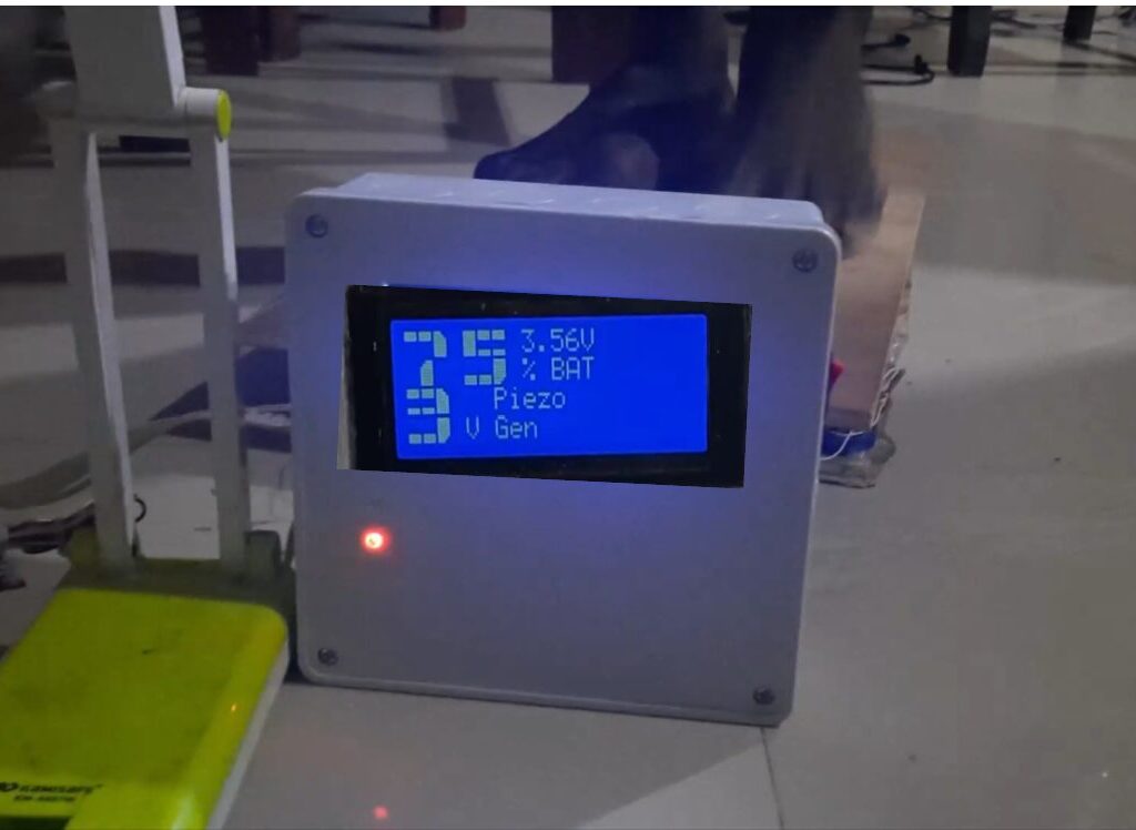
The Project design works as described in the flow chart above. Once the design is turned on, it checks the backup battery voltage, displays it on the LCD, also displays the voltage generated from the PZTs when stepped on. IF there is internet access, it will send these values to the IoT platform on Blynk cloud. And since a smart street light is connected as the actuator, it will power this load.
Read Also: Digital Temperature Monitor Using LM35 Sensor and Arduino
What Is IoT-Enabled Energy Generation?

IoT-enabled energy generation involves using IoT devices to monitor, optimize, or generate energy. By combining sensors, microcontrollers, and connectivity modules, these systems provide real-time data and control capabilities. This project taps into energy harvesting using PZT transducers and leverages the ESP-01 module for IoT functionalities.
Read Also: IoT Smart Farming Practices for Enhancing Pollination Efficiency
Why PZT Transducers for Energy Harvesting?

PZT transducers are piezoelectric materials that generate electricity when subjected to mechanical stress. Commonly found in applications like sensors and actuators, these devices are ideal for harvesting small amounts of energy from movements like vibrations, pressure, or footsteps.
- Compact and lightweight: Easy to integrate into compact designs.
- Durable: Can withstand repeated mechanical stresses.
- Eco-friendly: Generates clean energy with no emissions.
Read Also: IoT-Based Early Warning Systems for Frost Detection in Orchards
Components and Materials Required for This Project Design

Here’s what you’ll need:
- PZT transducers: Multiple units for harvesting energy.
- ESP-01 module: A Wi-Fi-enabled microcontroller for IoT.
- Arduino Mega board, the ch340 compact type
- Rechargeable battery: To store the energy generated.
- DC-DC buck converter: To buck down DC voltage
- Voltage Regulator: To stabilize the output from PZT transducers.
- LED lights: For the smart lighting component.
- Resistors and capacitors: For circuit design.
- Diodes: To prevent reverse current flow.
- Breadboard and jumper wires: For prototyping.
- Micro USB cable and adapter: For powering and programming the ESP-01.

The Arduino Mega board was the brain of the project design, we used the ESP-01 as another dev board that would send the values measured to the IoT platform. The relationship between these two dev boards are in the way they were connected using the the Serial Communication Protocol. The Arduino Mega board would send data to the ESP-01 and the ESP-01 would receive this data and using internet connectivity, send it to the Blynk cloud.
Read Also: The History of Money: From Barter to Cryptocurrency
Step 1: The Circuit Design: Understanding the Circuit Design

Explanation of Circuit Diagram
The above circuit diagram was designed in Fritzing and it shows the connection of the energy harvesting/generation part that is made up of the piezo-electric transducers (PZTs) section. The PZTs were connected both in parallel and in series connection to maximize output. The output voltage which in an A.C waveform was connected to the bridge rectifier to convert it to DC form.
We used a resistor of suitable value to form a voltage regulator and a Zener diode to ensure that is achieved. We connected this to the backup battery. The output of the battery is connected to a DC-DC buck converter to regulate an output of stable 5V that was used to power the Microcontrollers (MCUs) and peripherals in the circuitry.

The actuator load, the smart streetlight, has the connection as shown above, we did the connection by plugging into the connector socket making it plug and play.
To harness energy and control it efficiently, the circuit comprises three main parts:
- Energy harvesting circuit:
- Connect PZT transducers in parallel to maximize energy output.
- Use a diode bridge rectifier to convert AC voltage from the PZTs to DC.
- Add a capacitor to smooth the DC output if possible.
- Energy storage circuit:
- Feed the smoothed DC voltage into a rechargeable battery.
- Include a voltage regulator to ensure consistent output for the, Arduino Mega, ESP-01 and LED lights.
- IoT control circuit:
- Connect the ESP-01 module to the battery.
- Integrate the ESP-01 with LEDs for smart lighting functionality.
Read Also: Embracing Imperfections: The Path to a Happier Life
Step 2: Programming the Arduino Mega and ESP-01 Module

The Arduino Mega acts as the brain of this project. Here’s how to set it and the ESP-01 up alongside the Arduino IDE:
- Install the Arduino IDE:
- Download and install the Arduino IDE.
- Add the ESP8266 board to the IDE by going to File > Preferences and adding the appropriate URL in the “Additional Board Manager URLs” field.
- Write the code:
- The Arduino Mega would will control the LEDs based on user commands sent via a smartphone app or web interface. Whereas the ESP-01 would be the bridge between the IoT platform and the Arduino Mega baord.
- Use libraries like
WiFi.handblynk.hto handle connectivity and communication.
// include the library code:
#include <LiquidCrystal.h>
#include <EEPROM.h>
#include <BigCrystal.h>
#include <BigFont.h>
#include <SoftwareSerial.h>

// initialize the library with the numbers of the interface pins
LiquidCrystal lcd(9, 13, 22, 25, 27, 29);
BigCrystal bigCrystal(&lcd);

int volt;
float voltage1;

float low = 3.2;
float full = 10.0;
//for the ESP-01
#define gpio0 18  //used for software serial
#define gpio1 28
#define gpio2 20  //used for software serial
#define gpio3 30
//the serial comm.
SoftwareSerial arduino(gpio2, gpio0);
//for LDR
#define ldrPin A2
//for pirSensor
#define pirSensorPin 7
//for the transistor
#define transistorBase 11

// Define analog input for battery
#define ANALOG_IN_PIN A1
// Floats for ADC voltage & Input voltage
float adc_voltage = 0.0;
float in_voltage = 0.0;
// Floats for resistor values in divider (in ohms)
float R1 = 32380.0;
float R2 = 11760.0;
// Float for Reference Voltage
float ref_voltage = 5.0;
// Integer for ADC value
int adc_value = 0;

//define parameters for piezo generator
float R3 = 30000.0;
float R4 = 7500.0;
#define ANALOG_IN_PIN1 A0
// Floats for ADC voltage & Input voltage
float adc_voltage1 = 0.0;
float in_voltage1 = 0.0;
// Float for Reference Voltage
float ref_voltage1 = 5.0;
// Integer for ADC value
int adc_value1 = 0;
int readButton;


void setup() {
  // set up the LCD's number of columns and rows:
  lcd.begin(20, 4);
  Serial.begin(9600);
  arduino.begin(115200);
  //declare the inputs and outputs
  pinMode(transistorBase, OUTPUT);
  pinMode(pirSensorPin, INPUT);
  pinMode(ldrPin, INPUT);
  pinMode(gpio1, INPUT);
  pinMode(gpio3, INPUT);
  //write a welcome msg on lcd
  lcd.setCursor(2, 0);
  lcd.print("...WELCOME...");
  lcd.setCursor(3, 1);
  lcd.print("MR. BUKOLA ");
  delay(3000);
  lcd.clear();
  lcd.setCursor(4, 0);
  lcd.print("FOOT-STEP");
  lcd.setCursor(2, 1);
  lcd.print("PIEZOELECTRIC");
  lcd.setCursor(3, 2);
  lcd.print(" GENERATOR");
  lcd.setCursor(3, 30);
  lcd.print("  PROJECT");
  delay(3000);
  lcd.clear();
  for (int x = 0; x < 16; x++) {
    lcd.setCursor(0, 0);
    lcd.print("Checking Battery  ");
    lcd.setCursor(x, 1);
    lcd.print("*");
    delay(200);
  }
  lcd.clear();
}

float readBatteryVoltage() {
  // Read the Analog Input
  adc_value = analogRead(ANALOG_IN_PIN);

  // Determine voltage at ADC input
  adc_voltage = (adc_value * ref_voltage) / 1024.0;

  // Calculate voltage at divider input
  in_voltage = adc_voltage * (R1 + R2) / R2;

  // Print results to Serial Monitor to 2 decimal places
  // Serial.print("Input Voltage = ");
  // Serial.println(in_voltage, 2);
  return in_voltage;
}

float readPiezoGenVoltage() {
  // Read the Analog Input
  adc_value1 = analogRead(ANALOG_IN_PIN1);

  // Determine voltage at ADC input
  adc_voltage1 = (adc_value1 * ref_voltage1) / 1024.0;

  // Calculate voltage at divider input
  in_voltage1 = adc_voltage1 * (R3 + R4) / R4;

  // Print results to Serial Monitor to 2 decimal places
  // Serial.print("Input Voltage = ");
  // Serial.println(in_voltage1, 2);
  return in_voltage1;
}

int readOnlineStreetlightButton() {
  readButton = digitalRead(gpio1);
  Serial.print("Online Control Button: ");
  Serial.println(readButton);
  return readButton;
}

int checkNightTime() {
  readOnlineStreetlightButton();
  int checkLDR = analogRead(ldrPin);
  int checkPir = digitalRead(pirSensorPin);
  if (readButton == 1) {
    if (checkLDR < 200) {
      analogWrite(transistorBase, 25);
      if (checkPir == 1) {
        analogWrite(transistorBase, 255);
      }
    } else {
      digitalWrite(transistorBase, LOW);
    }
  }

  else {
  Serial.println("remote control disabled");
  }

  Serial.print("LDR reading: ");
  Serial.print(checkLDR);
  Serial.print(" PIR reading: ");
  Serial.println(checkPir);
}

void displayBattVoltage() {
  readBatteryVoltage();
  float batPercent = map(in_voltage, 0.11, 4.2, 0.0, 100.0);
  // Serial.print(batPercent);
  // Serial.println();
  batPercent = constrain(batPercent, 0, 99);
  // buffer to hold the converted variable having a length that is +1 of the variable lentgh
  char buffer[5];
  itoa(batPercent, buffer, 10);
  //dtostrf (floatVar, minStringWidthIncDecimalPoint, numVarsAfterDecimal, charBuf)
  // char buffer[5];
  //  dtostrf (batPercent, 0, 1, buffer);
  bigCrystal.printBig(buffer, 0, 0);
  bigCrystal.print("%");
  int number_count = 1;
  int number_temp = int(batPercent);
  while (number_temp != 0) {
    number_count++;
    number_temp /= 10;
  }
  number_count -= 1;
  if (batPercent < 1) { number_count = 1; }
  lcd.setCursor(0 + (number_count * 4), 0);
  bigCrystal.print(in_voltage);
  bigCrystal.print("V  ");
  lcd.setCursor(1 + (number_count * 4), 1);
  lcd.print(" BAT   ");


  Serial.print("Bat3 Percent:  ");
  Serial.print(batPercent);
  Serial.print("%");

  Serial.print(" Batt Voltage: ");
  Serial.print(in_voltage);  //print the voltge
  Serial.print("V");

  Serial.print(" Batt analogRead: ");
  Serial.println(adc_value);
}


void displayPiezoGen() {
  readPiezoGenVoltage();
  int readPiezoPin = analogRead(A0);
  // buffer to hold the converted variable having a length that is +1 of the variable lentgh
  char buffer[5];
  itoa(in_voltage1, buffer, 10);
  bigCrystal.printBig(buffer, 0, 2);
  bigCrystal.print("V");
  int number_count = 1;
  int number_temp = int(in_voltage1);
  while (number_temp != 0) {
    number_count++;
    number_temp /= 10;
  }
  number_count -= 1;
  if (in_voltage1 < 1) { number_count = 1; }
  lcd.setCursor(0 + (number_count * 4), 2);
  bigCrystal.print("  Piezo    ");
  lcd.setCursor(1 + (number_count * 4), 3);
  lcd.print(" Gen     ");
  Serial.print("Piezo Pin: ");
  Serial.print(readPiezoPin);
  Serial.print(" Piezo Voltage: ");
  Serial.print(in_voltage1);  //print the voltge
  Serial.println("V");
}


void loop() {
  checkNightTime();
  displayBattVoltage();
  displayPiezoGen();
  //send to the ESP01 dev board via serial comm.
  arduino.print(in_voltage);
  arduino.print("A");
  arduino.print(in_voltage1);
  arduino.print("B");
  arduino.print("\n");

  delay(1000);
  Serial.println("\n");
}
- Upload the code:
- Connect the Arduino Mega to your computer using a USB cord.
- Also, connect the ESP-01 to your computer using an adapter.
- Select the appropriate board and port in the Arduino IDE.
- Upload the codes respectively.
#include <SoftwareSerial.h>
/*ESP-01 pins are GPIO, Tx is GPIO1 (here define as 1, code line 6),
*/
#define rxPin 0 // GPIO0 is the pin next to the ESP-01 Rx pin. The Rx (GPIO3), the Tx (GPIO1)
#define txPin 2 //GPIO2
#define pumpVirtualPin 1
#define pumpVirtualPin1 3

SoftwareSerial nodeMCU(rxPin, txPin);
#define BLYNK_TEMPLATE_ID "TMPL23r_9ngTn"
#define BLYNK_TEMPLATE_NAME "Footstep IoT Project"
#define BLYNK_AUTH_TOKEN "_lxtDgv0m1Ihzc6-w_003KNlfpa6usiX"

/* Comment this out to disable prints and save space */
#define BLYNK_PRINT Serial

int Button, Button1;

#include <ESP8266WiFi.h>
#include <BlynkSimpleEsp8266.h>

// Your WiFi credentials.
// Set password to "" for open networks.
char ssid[] = "Galaxy A51 917E";
char pass[] = "tosin@345";

BlynkTimer timer;

char c;
String dataIn;
int8_t indexOfA, indexOfB,indexOfC, indexOfD;
String data1, data2, data3, data4;

BLYNK_WRITE(V2) {
  Button = param.asInt();
    if (Button==1){
      digitalWrite(pumpVirtualPin, HIGH);
    }
else if(Button==0){
 digitalWrite(pumpVirtualPin, LOW);
    }
}

BLYNK_WRITE(V3) {
  Button1 = param.asInt();
    if (Button1==1){
      digitalWrite(pumpVirtualPin1, HIGH);
    }
else if(Button==0){
 digitalWrite(pumpVirtualPin1, LOW);
    }
}

void setup(){
  // Debug console
  Serial.begin(115200);
  nodeMCU.begin(115200);

  pinMode(pumpVirtualPin, OUTPUT);

  Blynk.begin(BLYNK_AUTH_TOKEN, ssid, pass);
   // Setup a function to be called every second
  //timer.setInterval(1000L, parse_data);
}

void recvData(){
  while(nodeMCU.available() >0){
  c = nodeMCU.read();

   if( c == '\n'){
    break;
  }

  else{
    dataIn += c;
  }
}

if(c == '\n'){
  //Serial.println(c);
  parse_data();

  Serial.println("data 1= " + data1);
  Serial.println("data 2= " + data2);
  Serial.println("............................");

  c = 0;
  dataIn = "";
  }
}

void loop(){
  recvData();

  Blynk.run();
  timer.run();

}

void parse_data(){
  indexOfA = dataIn.indexOf("A");
  indexOfB = dataIn.indexOf("B");


  data1 = dataIn.substring(0, indexOfA);
  data2 = dataIn.substring(indexOfA+1, indexOfB);


   float ch1 = data1.toFloat();
   float ch2 = data2.toFloat();

    Blynk.virtualWrite(V0, ch1);
    Blynk.virtualWrite(V1, ch2);


}
Explanation of Arduino Code
The provided Arduino code is designed to control a system that utilizes an ESP-01 module for IoT applications, specifically focusing on managing a pump based on user input from the Blynk platform. The code begins by including the necessary libraries and defining pin configurations for the ESP-01’s RX and TX pins, as well as virtual pins for controlling two pumps. It initializes a SoftwareSerial object for communication with the ESP-01 and sets up Blynk authentication details, including template ID and authentication token. The setup() function configures the serial communication, initializes the pump pins as outputs, and establishes a connection to the Blynk server using provided WiFi credentials.
In the loop() function, the code continuously checks for incoming data from the ESP-01 module using the recvData() function. This function reads data until a newline character is detected, at which point it calls parse_data() to extract relevant information. The extracted data is then sent to Blynk’s virtual pins for monitoring. Additionally, two Blynk write functions (BLYNK_WRITE) are defined to handle button presses from the Blynk app, allowing users to turn the pumps on or off based on their input. Overall, this code enables remote control of pumps through an Internet connection while providing real-time feedback on their status via the Blynk application.
Read Also: How Long Would It Take a Hacker to Brute Force Your Password?
Step 3: Assembling the Hardware
Now, it’s time to bring everything together:

- Energy harvesting module:
- Mount the PZT transducers on a surface that experiences regular vibrations ( a staircase or floor).
- Connect the output to the diode bridge rectifier.
- Energy storage module:
- Attach the rectified output to the rechargeable battery via the voltage regulator.
- IoT module:
- Connect the Arduino to the battery and LEDs.
- Test connectivity and ensure the ESP-01 can send signals to the Arduino that can control the LEDs.
Step 4: Testing and Calibration

- Test energy generation:
- Apply mechanical stress to the PZT transducers and measure the voltage output.
- Verify that the rectified voltage is sufficient to charge the battery.
- Test IoT functionality:
- Access the ESP-01’s web interface using a smartphone or laptop.
- Send commands, by toggling the online button on to turn the LEDs on and off turn it off.
- Fine-tune placement:
- Adjust the placement of PZT transducers for optimal energy generation.
Real-Life Applications
This project demonstrates a scalable approach to renewable energy and smart technology. Potential applications include:
- Smart homes: Motion-powered lighting for hallways and staircases.
- Public spaces: Energy-harvesting tiles for streetlights.
- Wearables: Powering sensors using body movements.
Challenges and Troubleshooting Tips
- Low energy output:
- Combine multiple PZT transducers.
- Use high-efficiency voltage regulators.
- ESP-01 connectivity issues:
- Check Wi-Fi credentials and signal strength.
- Reflash the firmware if necessary.
- LED flickering:
- Add capacitors to smooth the power supply.
Environmental Benefits
By harnessing renewable energy and using IoT for smart control, this project reduces reliance on traditional energy sources. It’s a small step toward a sustainable future.
Conclusion
This DIY project combines the innovative concepts of IoT, energy harvesting, and smart lighting to create a practical and sustainable solution, an IoT-Enabled Energy Generation and Smart Lighting. Whether you’re a hobbyist or a professional, this project is an excellent way to explore the potential of piezoelectric transducers and IoT technology. Why not give it a try and make your home a little smarter while contributing to a greener planet?
FAQs
1. Can I use other microcontrollers instead of Arduino Mega and ESP-01?
Yes, you can use other microcontrollers like ESP32, Arduino Uno with a Wi-Fi shield, or NodeMCU for added flexibility and features.
2. How much energy can a PZT transducer generate?
The energy output depends on the size and quality of the PZT transducer, but typically it ranges from micro-watts to milliwatts.
3. Is this project suitable for beginners?
Yes, with basic knowledge of electronics and programming, beginners can successfully complete this project.
4. Can I expand this project to power more devices?
Yes, by adding more PZT transducers and larger storage components, you can scale up the system to power additional devices.
5. What apps can I use to control the ESP-01?
You can use web browsers, Blynk, or custom IoT apps to send commands to the ESP-01.

