In today’s post, we will be using the infrared (IR) receiver sensor module to detect infrared signals from an old TV remote and use the HEX file generated when we send signals to the IR receiver sensor module to control simple displays like LEDs and perhaps later use it to control an electric fan. In this tutorial, how to use an Infrared (IR) receiver module with Arduino Development Board, we will cover understanding the IR receiver module and how to interface with the Arduino Uno. So let’s jump right into it. The Infrared (IR) receiver module with Arduino

How to Use Infrared (IR) receiver module with Arduino: Materials Needed:
- Infrared Receiver Sensor Module…..1pcs
- Arduino Uno board………………………….1pcs
- Generic Jumper wires………………………40pcs
- LED display………………………………………5 to 10pcs
The Circuit Diagram
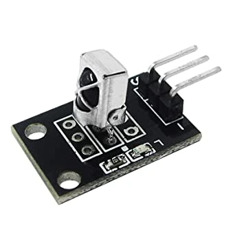
The IR receiver module has three terminals shown and named in the figure below:
From top-left to bottom-right, the first pin S is the pin we connect to any of the digital pins or analog pins of our choice on the Arduino development board. The second pin is the Vcc pin that is hooked up to the +5V of the Arduino development board. The third and last pin is the ground, which is connected to the header port labeled GND on the Arduino board. The connection on breadboard is thus:
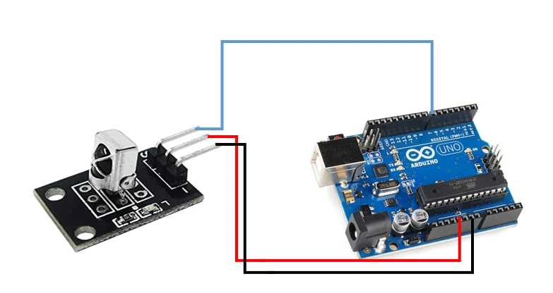
From the breadboard, the 5V output of the Arduino board is connected to pin 2 of the IR receiver module, both the IR receiver module and Arduino Uno board have a common ground.
Step-by-Step To Program the Infrared (IR) receiver module with Arduino Project
Get Your Arduino Board Ready
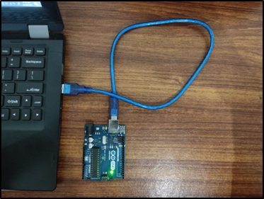
Next, plug in your Arduino communication cable into the USB port of your PC, open your Arduino IDE, click File, create a new file, and you can name it whatever you want, and save your sketch.
Download and Import the Necessary Libraries for the Infrared (IR) receiver module with Arduino
We saved ours with IR_Receiver_Test. You might want to do the same.
To use the Infrared remote on the Arduino, we need to import a special library, known as the IRremote. Once downloaded from the github page, click on the sketch tab, include library, and Add ZIP library.
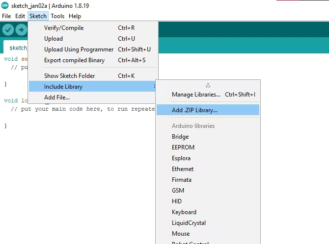
In the list of libraries, you will find your new added library, IRremote, quickly add then and copy the code below to get your HEX codes.
The Arduino Source Code
#include <boarddefs.h>
#include <IRremote.h>
#include <IRremoteInt.h>
#include <ir_Lego_PF_BitStreamEncoder.h>

//state the IR input to the MCU
#define RECV_PIN A1
//make it recognised to IR Lib
IRrecv irrecv(RECV_PIN);
//ask it it get results and save it
decode_results results;

void setup() {
  //enable the IR
  irrecv.enableIRIn();
  //begin the serial monitor comm
  Serial.begin(9600);
}

void loop() {
 if(irrecv.decode(&results))
  {
     irrecv.resume();
    //print the remote results in HEX codes
     Serial.println(results.value, HEX);
  }
Source Code Explanation
Basically, the code is used to generate your HEX codes from pointing and depressing any key on the home remote guide at the IR receiver sensor module. The brief explanation to it is thus: From line 1 to line 4, we included the IR remote libs, Only the IRremote.h header file is enough but it felt good leaving all the others there. Next, we defined the pin on the Arduino where we are connecting the signal pin of the IR of receiver, this we called Recv_Pin and we connected to analog pin 1, A1. Then we make it recognizable to the library. In the setup function, we enabled the IR receiver and begin the serial monitor and set our communication speed between the computer and the Arduino board with Serial.begin(9600) code line. In the loop function, we ask the Arduino to get results and display it on the serial monitor.
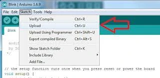
After this, we verify the code and upload it and wait while it finishes uploading.
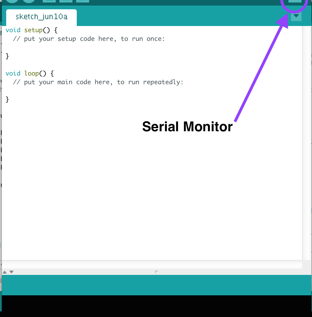
Open your serial monitor, by clicking on tools, serial monitor. Alternatively, you could click on the white search box.
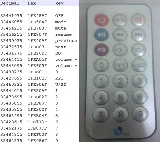
We then start getting the HEX code for each keypad on the TV remote, each key we press when we point at the IR receiver would display its own HEX code.
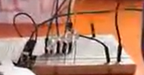
Now we can use this HEX codes to play around with the displays of our LEDs. We connected four LEDs as shown in the breadboard connection below:
Before we go back to our sourcecode to make some changes, we want to pick three different buttons on the old TV remote we want to use to cause changes to the way the LEDs display. after making this choice, we should save their HEX codes somewhere because we are going to be using it to in our next step.
Conditional If statements, and for loops
The if statements we would use here would help us to make comparisons and change the current state of the LEDs to another state when we want them. whereas the for loops would iterate our output LEDs as long as the conditions used in it is true. Otherwise it would stop executing the line of code in it.
#include <boarddefs.h>
#include <IRremote.h>
#include <IRremoteInt.h>
#include <ir_Lego_PF_BitStreamEncoder.h>

//state the IR input to the MCU
#define RECV_PIN A1
//make it recognised to IR Lib
IRrecv irrecv(RECV_PIN);
//ask it it get results and save it
decode_results results;

void setup() {
  //enable the IR
  irrecv.enableIRIn();
  //begin the serial monitor comm
  Serial.begin(9600);
  for(int i = 9; i < 14; i++){
  pinMode(i, OUTPUT);

  }
}

void loop() {

    if(irrecv.decode(&results))
  {
     irrecv.resume();
    //print the remote results in HEX codes
     Serial.println(results.value, HEX);
  }
  if(results.value == 0x4C){
  for(int i=9; i <14; i++){
    digitalWrite(i, HIGH);
    delay(250);
      }
      for(int i=9; i <14; i++){
    digitalWrite(i, LOW);
    delay(250);
      }
  }
  delay(1000);
}
Source Code Explanation
What the sketch does from code line 18 is; make the digital pins from digital pin 9 to digital pin 13 outputs using a for loop. Line 28 through 30 ask the Arduino Microcontroller to get the HEX codes sent from the IR transmitter of the home TV remote and print it out on the Serial monitor screen.
Line 32 through 42 uses the same if statement and comparism but with two for loops to check for when a specific button on the home TV remote is press and display the LEDs in a certain effect.
To use more buttons of the TV remote to display different effects, we use this sketch below:
#include <boarddefs.h>
#include <IRremote.h>
#include <IRremoteInt.h>
#include <ir_Lego_PF_BitStreamEncoder.h>

//state the IR input to the MCU
#define RECV_PIN A1
//make it recognised to IR Lib
IRrecv irrecv(RECV_PIN);
//ask it it get results and save it
decode_results results;

void setup() {
  //enable the IR
  irrecv.enableIRIn();
  //begin the serial monitor comm
  Serial.begin(9600);
  for(int i = 9; i < 14; i++){
  pinMode(i, OUTPUT);

  }
}

void loop() {

    if(irrecv.decode(&results))
  {
     irrecv.resume();
    //print the remote results in HEX codes
     Serial.println(results.value, HEX);
  }
  if(results.value == 0x4C)
  for(int i=9; i <14; i++){
    digitalWrite(i, HIGH);
    delay(250);
      }
      for(int i=9; i <14; i++){
    digitalWrite(i, LOW);
    delay(250);
      }

      if(results.value == 0x876){
        digitalWrite(11, HIGH);
        delay(200);
        digitalWrite(10, HIGH);
        digitalWrite(12, HIGH);
        delay(200);
        digitalWrite(13, HIGH);
        digitalWrite(9, HIGH);
        delay(500);
        digitalWrite(13, LOW);
        digitalWrite(9, LOW);
        delay(200);
        digitalWrite(10, LOW);
        digitalWrite(12, LOW);
        delay(200);
        digitalWrite(11, LOW);
             }
     if(results.value == 0x877){
      digitalWrite(13, HIGH);
      delay(200);
      digitalWrite(13, LOW);
      delay(200);
      digitalWrite(12, HIGH);
      delay(200);
      digitalWrite(12, LOW);
      delay(200);
      digitalWrite(11, HIGH);
      delay(200);
      digitalWrite(11, LOW);
      delay(200);
      digitalWrite(10, HIGH);
      delay(200);
      digitalWrite(10, LOW);
      delay(200);
      digitalWrite(9, HIGH);
      delay(200);
      digitalWrite(9, LOW);
      delay(200);
     }

  delay(1000);
}
The HEX codes should be prefixed with:- 0x for the MCU to recognize your if statements as shown in the source codes above. You can watch the YouTube video of it here; or simply click on the clip below.
Conclusion
We have successfully designed and constructed the project, How to Use Infrared (IR) receiver module with Arduino. Do you think you can replicate the same thing? Or better make it smarter than our own. Let us know if you did this project. We will like to see a photograph or video. Leave us a comment below.
Connect with us on Telegram, Instagram, Facebook page or WhatsApp.
Frequently Asked Questions on How to Use Infrared (IR) receiver module with Arduino
Basic Understanding
- What is an IR receiver module?
- How does it work?
- The IR receiver converts incoming infrared light into electrical signals that can be processed by an Arduino.
- Can I power the IR receiver module directly from the Arduino’s 5V pin?
- Yes, most IR receiver modules can be powered directly from the Arduino’s 5V pin. However, check the module’s datasheet for specific power requirements.
- What type of IR remote control can I use?
- Most standard TV remote controls will work. However, some specialized remote controls might require specific IR receiver modules.
Coding and Programming
- What libraries are available for decoding IR signals?
- The
IRremotelibrary is a popular choice for decoding IR signals.
- The
- How do I decode the received IR signals?
- The IRremote library provides functions to read and decode IR signals. You’ll typically need to capture the raw data and then decode it using the appropriate protocol (e.g., NEC, RC5).
- How do I differentiate between different buttons on the remote?
- Each button on the remote sends a unique code. You can use the decoded data to identify which button was pressed.
- How can I handle multiple IR remotes?
- You can use multiple IR receiver modules and assign different pins to each. However, handling multiple remote controls simultaneously can be complex.
- Why am I not receiving any IR signals?
- Check the connections, power supply, and the orientation of the IR receiver. Ensure the remote control is pointing directly at the receiver.
- Why am I getting inconsistent results?
- Interference from other electronic devices can affect IR signals. Try shielding the IR receiver or using a different frequency.
- How can I improve the range of the IR receiver?
- Using a higher-gain IR receiver or amplifying the received signal can increase the range.
- Can I use an IR receiver to transmit data?
- While primarily used for receiving data, IR can also be used for transmission with specific hardware and coding.
- How can I create my own IR remote control?
- There are dedicated IR transmitter modules and libraries available for encoding data and transmitting IR signals.
- What are some common IR protocols?
- NEC, RC5, and Sony are some of the common IR protocols used in remote controls.