Today, we are constructing a traditional power supply unit with a maximum output of 5V and 1A (or 3A with an LM323T DC supply). which we may subsequently utilize to power any of our microelectronics projects that require that level of DC power. Basic components of electronics engineering are required. You will learn how to construct a 5V linear power supply unit that can power your prototype electronics if you study this tutorial through to the finish.
What is a Linear Power Supply?
A linear power supply is a type of power supply that converts an AC input voltage to a regulated DC output voltage. The key components of a linear power supply include a transformer, rectifier, filter capacitor, and a voltage regulator. These components work together to ensure that the output voltage is stable and free from noise, even under varying load conditions.
Building a linear power supply is a rewarding project for electronics enthusiasts and professionals alike. Unlike switching power supplies, which can generate electrical noise, a linear power supply provides a clean and stable DC output, making it ideal for sensitive electronics applications. In this guide, we’ll go through the process of designing and constructing a 5V linear power supply.
Materials/Components
- 2A AC socket plug,
- 2A A.C switch (Rocker Switch),
- A 12V-0-12V transformer
- 9 meters of calculated millimeter diameter conduction wire
- (50mA- 2A) connector wires (generic jumper wires male or female)
- Full wave rectifying bridge
- 2 calculated capacitors values: 100f and 0.1f.
- L7805CV 5V voltage regulator IC
- 10K and 20k current-limiting resistors
- connector clips
- connector screws,
- insulating caps
- 2 Perforated boards (line version),
- 2 Light Emitting Diodes (LEDs).
How to Build Linear Power Supply Unit: 12V-0-12V Step-down AC Voltage Transformer
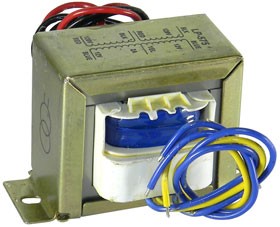
In order to convert 220V – 240V AC to a 5V DC, first we need a step-down transformer to reduce such high voltage. Here we have used 12V-0-12V 1A step-down transformer, which convert 220V AC to 12V AC on single coil and 24V on two coils. In a transformer component, there are primary and secondary coils which step up or step down the voltage according to the number of turns in the each of the coils.
Selection of a proper transformer is very important. Current rating depends upon the Current requirement of Load circuit. This transformer choice was made because the voltage rating of the transformer should be more than the required voltage of the output. Since we needed a 5V DC output supply, and the transformer with a rating of 12V is ideal. Because during voltage regulation, our voltage regulator IC need more voltage to operate. For example, L7805 needs at least need 2V more that’s 7V to provide a 5V voltage.
1mm Diameter Conduction Wire
The length of this type of conduction wires used here was determined by how long the sources of the power supplies are from the device. Choice made was based on calculation of conduction wire diameter; a 1mm diameter wire will give the material increase in resistance and less current capacity and decrease in heat loss. Hence, it will avoid quick burn out. From laws of Resistance;
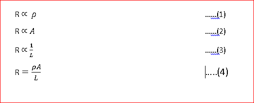
This means that the diameter of a cross-sectional area of the wire affects the current carrying capacity of the wire. The conduction wires here are 10A, 220/240 VAC.
Jumper Wires
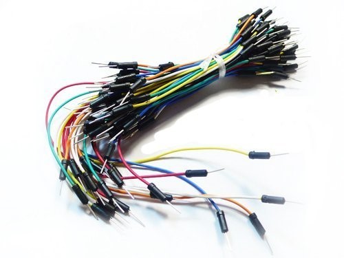
This electronics component was needed to conduct D.C voltage in the power supply unit (and other units). It helped us to avoid short circuits and open circuits in this/these unit(s). It also distributes suitable voltages to each component we used during the design.
Full Wave Bridge Rectifier VS048
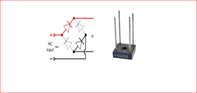
Rectification is the process of removing the negative part of the Alternate Current (AC), hence producing the partial DC. This can be achieved by using 4 power diodes. Diodes only allow current to flow in one direction (not completely true, because of minority carriers’ movement, avalanche breakdown and Peak Inverse voltage). In designing the power supply unit, two diodes D2 & D3 are needed in the first half cycle of AC, and are hence placed in the forward biased configuration. Another two power diodes, D1 and D4 are placed in the reversed biased configuration, and in the second half cycle (negative half) Diode D1 and D4 are forward biased and D2 and D3 are reversed biased. This Combination converts the negative half cycle into positive. Alternatively, we choose a full wave bridge rectifier component VS048 which consist that combination of 4 diodes internally.
A diode bridge makes use of four diodes in a bridge arrangement to attain full-wave rectification. This is more commonly known as a bridge rectifier. Its output is rectified DC from an AC source and the polarity is the same regardless of the polarity of the AC input. The resulting output waveform is not true DC, it contains a ripple. When used in power supplies to rectify the incoming AC the output waveform must be handled by the rest of the power supply circuitry to reduce its ripple thus making a clean DC output. Another application would be reverse polarity protection in the input of a battery circuit to make sure no damage would occur if a battery was inserted into a device with the wrong polarity. And we do not want this in this How to build Linear power supply unit tutorial guide.
Filter Capacitors
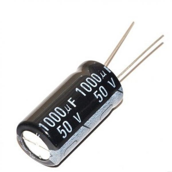
The output after the Rectification is not a proper DC, it is oscillation output and has a very high ripple factor. We don’t need that pulsating output, for this we use Capacitor. Capacitor charge till the waveform goes to its peak and discharge into Load circuit when waveform goes low. So when output is going low, capacitor maintains the proper voltage supply into the Load circuit, hence creating the DC. We thus calculated the value of the filter capacitor using the following formula:
C=(I ×t)/V = Q/V
C= capacitance to be calculated
I= Max output current (which is about 1000mA)
t = 10ms,
We will get wave of 100Hz frequency after converting 50Hz AC into DC, through full wave bridge rectifier. As the negative part of the pulse is converted into positive, one pulse will be counted two.
So the Time period, t, will be 1/100 = 0.01 Second = 10ms
 V = Peak voltage - voltage  given to voltage regulator.
 V= 5+2=7 (+2 more than rated means).
 Now, if 12-0-12 is the RMS value of transformer so peak voltage is:
Vrms × 1.414 = 12× 1.414= 16.968V
1.4V will be dropped on 2 diodes (0.7V per diode) as 2 diodes will be forward biased for half wave.
 Hence, 16.968V– 1.4V = 15.568V
 When capacitor discharges into load circuit, it must provide 7v to voltage regulator to work so finally V is:
 V = 15.568 – 7= 8.568v
 But since,  C=(I×t)/V
 C=(1000mA×10ms)/8.568v=(1×0.01)/8.568=1167µF≃1000µF
Voltage Regulators or Stabilizers
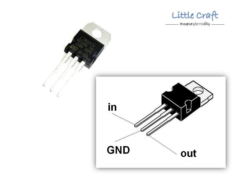
The voltage regulator IC, L805CV is used to provide a regulated 5V DC output. Input voltage should be 2 volts more than the rated output voltage for proper working of Integrated Circuit (IC), that means, for 5V DC output, at least 7v is needed (in which case, 16V was fed into it) Although most voltage regulator Integrated Circuit, can operate in input voltage range of 7-20V. Voltage regulators have all the circuitry inside it to provide a proper regulated DC. A capacitor of 0.01uF was connected to the output of the IC LM7805 to eliminate the noise, produced by transient changes in voltage.
Resistors
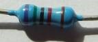
Resistors are electronics components that introduce some amount of resistance into a circuit. The values of the resistors incorporated in this project design for current limiting purposes ranged from 47Ω to 100KΩ. The resistors main functions here are used to protect current sensitive components like LEDs and to stepdown voltages to appropriate values.
Light Emitting Diode (LED)
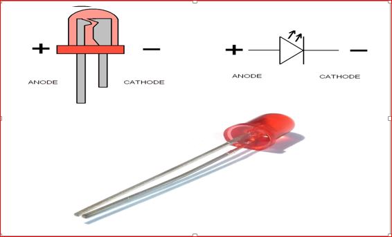
Also called Light Emitting Diodes, LEDs are diodes that basically convert electrical energy to light energy. The LEDs to be used here are Red and Green to show indication of supply either A.C or D.C. The Green LED would indicate that power has been connected to the Power Supply unit while the Red LED would indicate that the PSU system has started to draw A.C voltage supply from the A.C mains.
You will also need strip perforated boards for soldering and solder. you should have your soldering iron ready; soldering stand, solder wick and solder sucker.
Linear Power Supply Unit: The Circuit Diagram
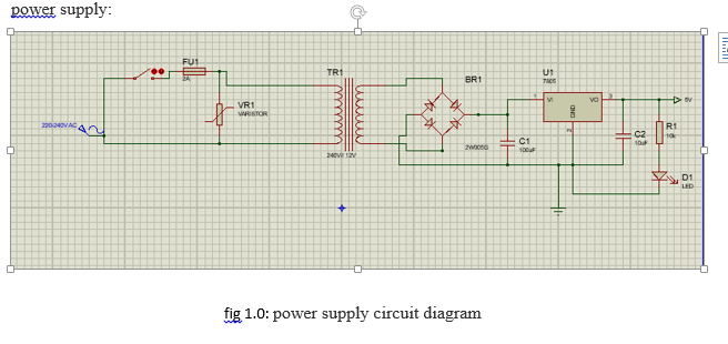
The power supply begins with a 10A AC plug connected to the AC loadpoint through a 13A red switch that is used to control the turning ON or OFF state of the power supply. The 13A Switch was connected in series to a 2A fuse. This was necessary for surge protection. In case of transients, the fuse would burn out thereby protecting the other components in the circuit. The step down transformer was used to reduce the AC voltage from 220V AC to 12V AC with current supply of 2A. The secondary side of the stepdown transformer is connected to a full wave bridge rectifier that converts the AC voltage to DC. The output of this contains ripples of AC current and hence a filtration electrolytic capacitor is connected in parallel to this output. From the capacitive reactance formular;
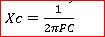
Since the AC voltage is now 100Hz that is 2 times its original 50hz frequency after rectification, Xc would be a definite value with the value of F= 100 plug into equation 1. And as such, the electrolytic capacitor would allow the AC ripples to pass through it and back to the source. But DC voltage has zero (0) frequency and becomes infinite in resistance when computed using that equation, as such all DC voltage cant pass through the electrolytic capacitor C1. Another important feature of this filtration capacitor is that it discharges to the load when the rectified voltage starts falling from the peak.
We can use LM7805 as our linear voltage regulator as shown in the circuit diagram. but if we are to power loads at 5V that would demand more current. Our best choice is to use LM323T linear voltage regulator. It can output more current than the LM7805 voltage regulator.
This linear regulator of output 5V 3A, LM323T is placed at the output of the filtration capacitor. This voltage stabilizer would clip off the incoming voltage from C1 to give out a regulated voltage of 5V 2A DC. In order to notice that we have a stable 5V output, an indicator LED, D1 was connected in parallel to this output. To protect it from damage due to excess current, a 10kΩ resistor was connected in series with it. When the power supply outputs 5V, it will glow.
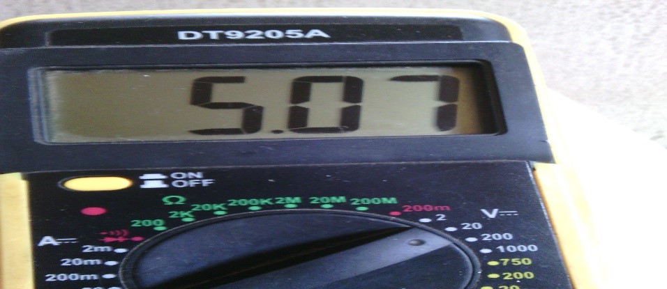
After soldering this circuit diagram, power it up, use your multimeter and measure the DC output. You will get your steady 5V output supply. as shown in the picture below:
Conclusion
Alright. We have covered the whole steps on how to design and build linear power supply with 5V output. Do you think you can do the same? Or perhaps, improve on this design, kindly let us know in the comment section below, We would love to see what you designed, send us your pictures or images on WhatsApp, Telegram group, Facebook or Instagram.
Thanks a lot.
Read More
- ARDUINO VOLTAGE SENSOR: HOW TO MEAUSURE SOLAR PANEL VOLTAGE
- FINAL YEAR PROJECTS FOR ENGINEERING STUDENTS
- ARDUINO VOLTAGE SENSOR: HOW TO MEASURE BATTERY VOLTAGE
FAQs on Linear Power Supply Systems
1. What are the advantages of a linear power supply?
- Linear power supplies offer low noise and ripple, making them ideal for sensitive analog and RF circuits. They also have a simpler design and are easier to troubleshoot compared to switching power supplies.
2. Why does the voltage regulator need a heatsink?
- The voltage regulator dissipates excess energy as heat when dropping the input voltage to the desired output level. A heatsink helps to cool the regulator, preventing it from overheating and ensuring reliable operation.
3. Can I use a linear power supply for high current applications?
- Linear power supplies are less efficient for high current applications due to the heat generated by the voltage regulator. For high current needs, a switching power supply might be more suitable, though at the expense of increased noise.
4. What is the purpose of the filter capacitor in a linear power supply?
- The filter capacitor smooths out the pulsating DC voltage after rectification, reducing voltage ripple and providing a more stable DC output.
5. How do I choose the right transformer for my power supply?
- The transformer should have a secondary voltage that is slightly higher than the desired output voltage, allowing for sufficient headroom for the voltage regulator to operate effectively. Consider the current rating as well to ensure it can handle your load.

