Introduction
Gas leaks can be dangerous, leading to fires, explosions, and even carbon monoxide poisoning. In this blog post, we’ll show you how to build a smart gas leak detector with Arduino and Blynk IoT to keep your home safe.
The project focuses on detecting gas leaks like that of cooking gas, carbon monoxide, and carbon (IV) oxide gas in a resident setting. We designed a prototype model that will be able be monitor and display the sensor readings for these parameters on a Blynk IoT dashboard. The design is equipped with in-app alert that can notify the user remotely anywhere they are around the globe. And the hardware installed give a buzzing tone in the case of gas leak detection.
For intermediate Arduino hobbyists looking to improve their gas detection projects, this blog post is designed for them. We’ll investigate methods for calibrating sensors, develop a Blynk app for push notifications and real-time data visualization, and examine the underlying code.
Why Gas Detection Matters
Undetected gas leaks can be life-threatening. A smart gas detector can provide early warnings, giving you time to address the issue before it becomes a serious problem.
Your sensor will continue to be accurate and produce accurate data if it is calibrated on a regular basis. In order to calibrate the sensor, it must be exposed to pure air (or, for some models, a known concentration of gas) and its internal parameters must be adjusted for best results.
Getting Started
To build your gas detector, you’ll need an Arduino Nanoo board, a gas sensor, jumper wires, and the Blynk app. The full components and materials used for this project design are listed in the table below.
Components and Materials
| ITEM DESCRIPTION | QUANTITY |
| LiPo CHARGING MODULE | 1 |
| LCD Module | 1 |
| 3×6 INCH PATRESS BOX | 1 |
| Connector | 3 |
| RESISTORS | 2 |
| CONNECTING WIRES | 3 yards |
| DHT11 Sensor | 1 |
| MQ135 SENSOR | 1 |
| LIPO BATTERY | 1 |
| SOLDER | 1 |
| SOLDERING IRON | 1 |
| Buzzer | 1 |
| ARDUINO NANO BOARD | 1 |
| MQ-7 GAS SENSOR | 11 |
| BUZZER | 1 |
| OLED MODULE | 1 |
| MQ-2 GAS SENSOR | 1 |
| DC SWITCH | 1 |
| FEMALE HEADERPIN | 2 |
| MISCELLANEOUS |
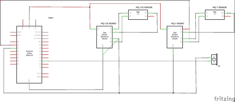
Schematic (Circuit) Diagram of the Gas Leak Detector with Arduino and Blynk IoT
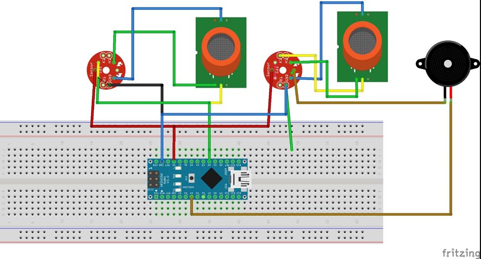
The Gas Leak Detector with Arduino and Blynk IoT Project design ran on Arduino Nano board since the sensors needed 5V for operation; also, since the ESP8266-01 needed 3.3V for its operation, the onboard 3.3V regulator on the gave us that choice, hence why we opted for its use.
Explanation of the Schematic Diagram
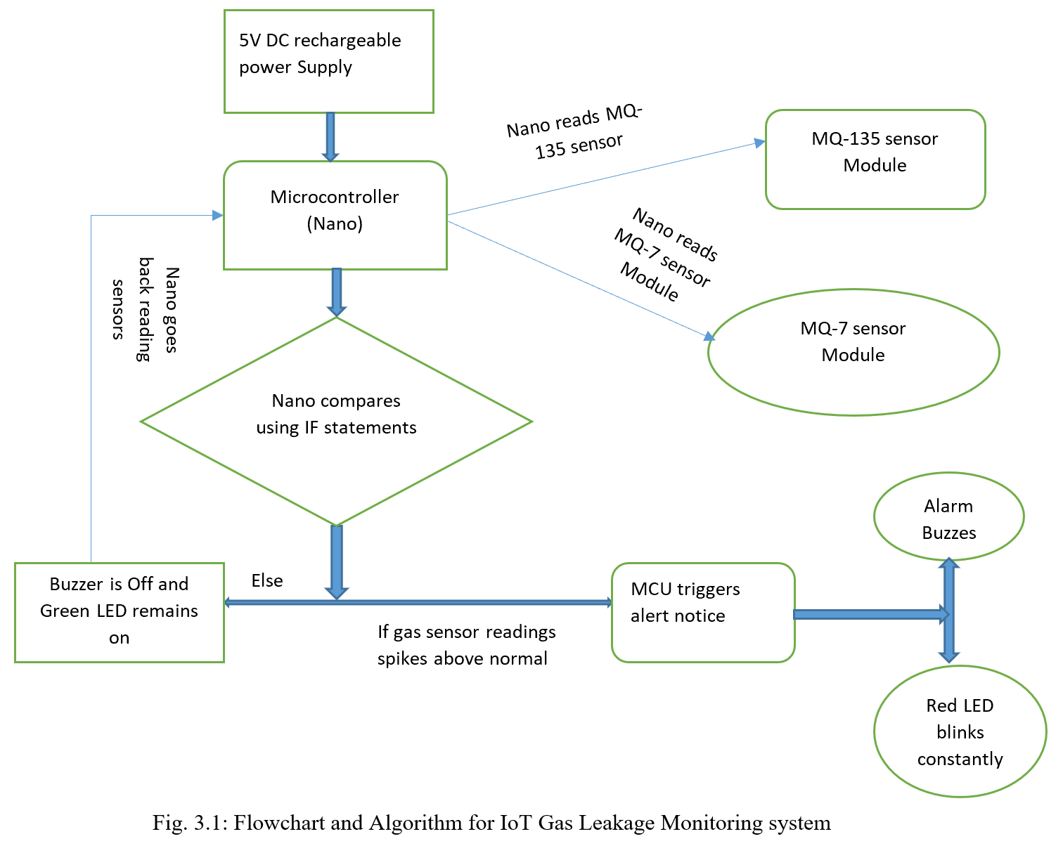
The project was developed using an Arduino Nano development board. The development board measures the concentration of harmful gaseous substances in the environment that humans breathe in through the MQ-7 Carbon Monoxide (CO) and MQ-135 gas sensor modules. The Nano reads the gas module using analog signal converter (ADC) pins. Then we programmed it to check for a threshold where the gas concentration level should exceed, and the buzzer alarm would go off; notifying people around us that the area was unsafe to breathe in.
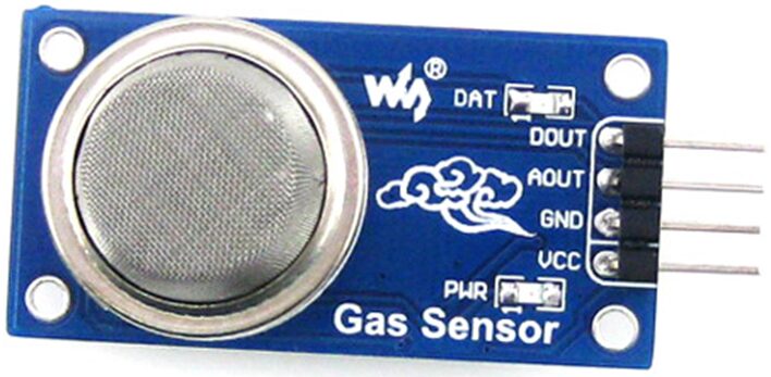
The analog pin of the MQ-7, MQ-135 and MQ-2 gas sensors are connected to analog pin 0 (A0), analog pin 1 (A1), and analog pin 2 (A2) on the Arduino Nano respectively, while its Vcc and Gnd Pins are connected to the 5V and ground on the Nano board respectively too. The Dout (digital output) pin of these sensors are not connected but left “flying”. When powered, the power on indicator LED on the gas sensors came on and when harmful gas substances which it can detect is placed in its proximity, the sensing onboard LED also lit up.
Programming the Arduino
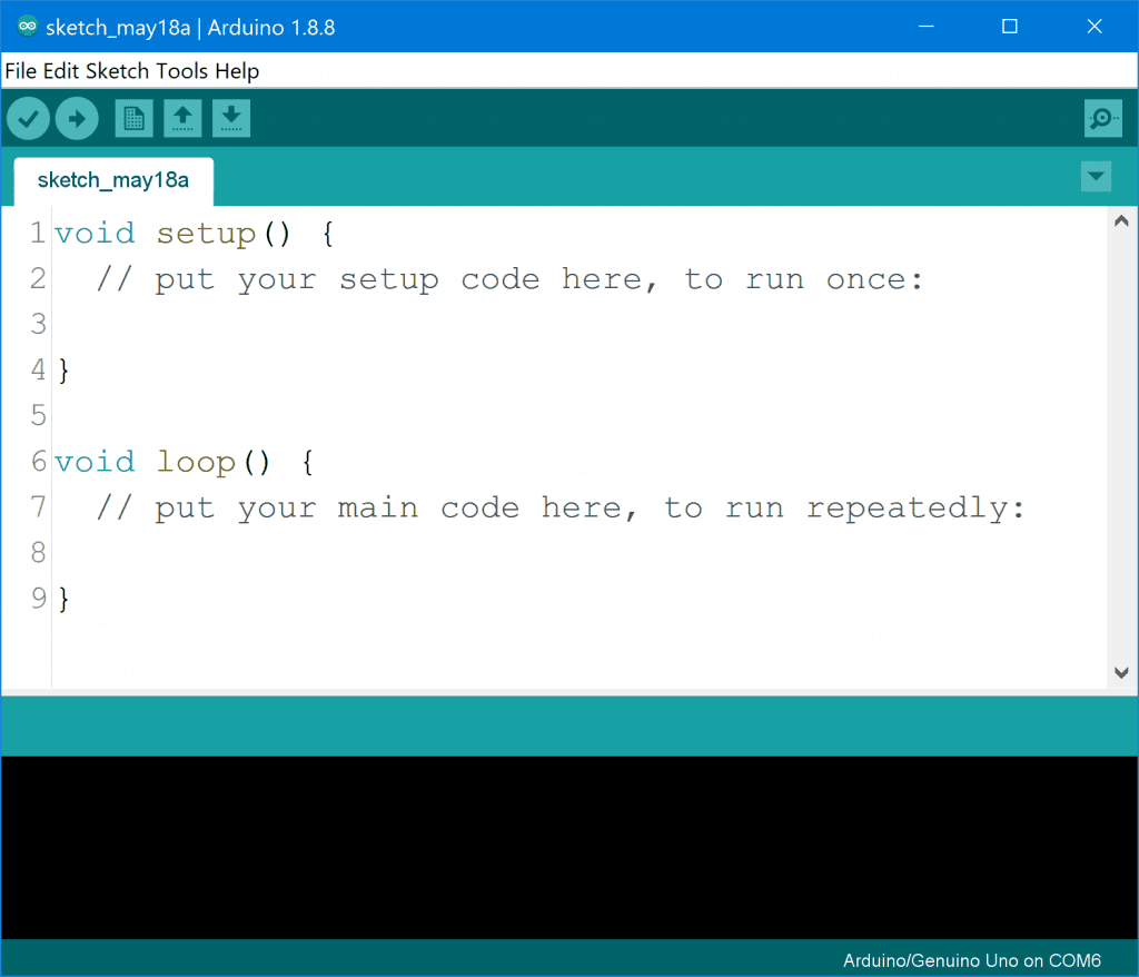
Download the Arduino IDE
Download the Arduino IDE from the Arduino website here. You can choose the latest version of Arduino IDE or choose an older version. We recommend using the latest version though. Once you have downloaded and installed the Arduino IDE, you can proceed to opening it. Once the IDE opens up, you will see something like the image above. This means you are on the right path already.
Install the libraries Needed
For this Gas Leak Detector with Arduino and Blynk IoT project, we will need the Blynk library. Particualry, the ESP8266-01 Blynk library, since we are using the ESP8266-01 module as a peripheral for WiFi station for WiFi networks with internet access.
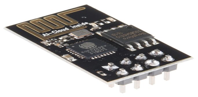
You can proceed to download this library from the Blynk page here. We simply use the library manager in the Arduino IDE to get the same library. It is important that you try to make this ESP8266-01 module connect to the Arduino Nano board in serial communication protocol. This will make programming this project a little bit easier.
You May Also Like…
- IoT Pump Control for Efficient Irrigation Systems
- IoT Pump Control Irrigation System Using ESP32 Arduino
- Internet of Things (IoT) Projects Using Arduino – 10 Amazing Arduino DIY Projects
- How to Make Money From Blogging in 2024
Setting Up the Blynk App

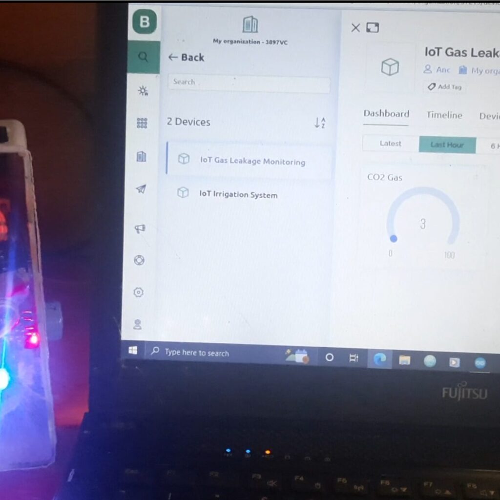
To get started in showing the readings of the sensor on a remote Blynk server. We registered on their website here. Also you can download the Blynk app from the App Store or Google Play and create a new project.
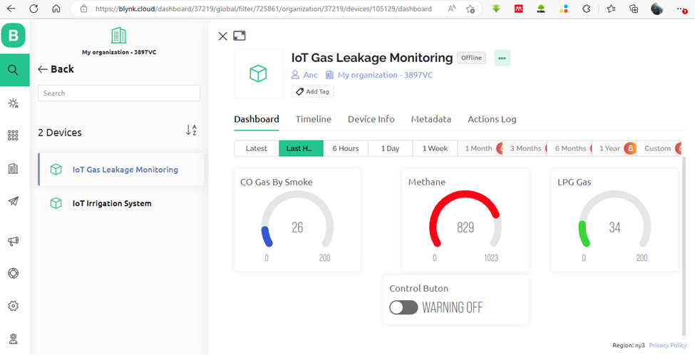
They provided us with the widget like the display widget where the gas sensor readings can be displayed. The platform was also used to blynk platform to create a switch widget where we could “stimulate” the dangerous gases concentrations.
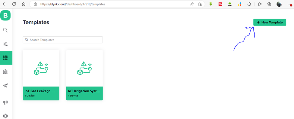
After registration, you need to go to the developer side and create a new template as shown in the picture above by the crooked arrow. This is done by selecting the template tab and clicking on “New Template”. This will bring out a form where the name of the template can be inputted.
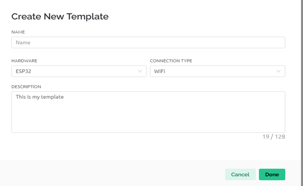
After naming and putting the details of the template, the next is to select the “Datastreams”. We created virtual Datastreams and after that, we saved the templates and created a device for this templates. The final step is shown below.
And this we can add this in the “my device section”. And from there, load it up
The Arduino Source Code for Gas Leak Detector with Arduino and Blynk IoT
#include <SPI.h>
#include <Wire.h>
#include <Adafruit_GFX.h>
#include <Adafruit_SSD1306.h>
#include <SoftwareSerial.h>

#define SCREEN_WIDTH 128 // OLED display width, in pixels
#define SCREEN_HEIGHT 64 // OLED display height, in pixels
// Declaration for an SSD1306 display connected to I2C (SDA, SCL pins)
#define OLED_RESET     8 // Reset pin # (or -1 if sharing Arduino reset pin)
Adafruit_SSD1306 display(SCREEN_WIDTH, SCREEN_HEIGHT, &Wire, OLED_RESET);

#define coSensorPin A3   //MQ135 analog pinout
#define methaneSensorPin A2    //MQ4 analog pinout
// #define coSensorDout 19  //for MQ135
// #define methaneSensorDout 18  //for MQ4

#define buzzerPin 4
#define redLED 5
#define blueLED 7
#define greenLED 6
#define flagButtonPin 9

int readCO, readCO2, readMethane, readLPG, readBlynkButton;
int n, p, k;
String greeting = "hello";

int minValue = 0;
int maxValue = 100;
int oneQuaterCO, oneThirdCO, oneQuaterLPG, oneThirdLPG;

SoftwareSerial arduino(2, 3);

void setup(){
  pinMode(flagButtonPin, INPUT);
  pinMode(buzzerPin, OUTPUT);
  pinMode(redLED, OUTPUT);
  pinMode(blueLED, OUTPUT);
  pinMode(greenLED, OUTPUT);
  // Debug console
  Serial.begin(115200);
  arduino.begin(115200);

// SSD1306_SWITCHCAPVCC = generate display voltage from 3.3V internally
  if(!display.begin(SSD1306_SWITCHCAPVCC, 0x3C)) { // Address 0x3C for 128x32
    Serial.println(F("SSD1306 allocation failed"));
    for(;;); // Don't proceed, loop forever
  }

  display.clearDisplay();
  display.setTextSize(1);             // Normal 1:1 pixel scale
  display.setTextColor(SSD1306_WHITE);        // Draw white text
  display.setCursor(30,0);             // Start at top-left corner
  display.println(F("  WELCOME "));
  display.setCursor(20,20);
  display.println(F("SMART GAS SENSOR "));
  display.setCursor(20,40);
  display.println(F("MONITORING PROJECT"));
  display.display();
  delay(3000);
  // Setup a function to be called every second
  blinkBlueLED();
 }

void sendSensor(){
    mq7Sensor();
    mq135Sensor();
    mq2Sensor();

 readBlynkButton = digitalRead(flagButtonPin);

  if(readBlynkButton == 0){
        if((readCO >= 96) || (readMethane >= 845) || (readLPG >= 95)){
            displayOledWarning();
            blinkRedLED();
            buzzerAlert();
                }
        else if(((readCO >= 30) && (readCO <= 67)) || ((readMethane >= 30) && (readMethane <= 67))){
            digitalWrite(buzzerPin, LOW);
            displayOledGreen();
            blinkBlueLED();
                }
        else{
            digitalWrite(buzzerPin, LOW);
            displayOledGreen();
            blinkGreenLED();
            }

      }

  if(readBlynkButton == 1){
    readCO = 995;
    readLPG = 998;
    readMethane = 997;

    buzzerAlert();
    displayOledWarning();
    blinkRedLED();
  }

    arduino.print(readCO);     arduino.print("A");
    arduino.print(readMethane);     arduino.print("B");
    arduino.print(readLPG);     arduino.print("C");
    arduino.print("\n");
 }

void buzzerAlert(){
  digitalWrite(buzzerPin, HIGH);
  delay(1000);
  digitalWrite(buzzerPin, LOW);
  delay(500);
}

void blinkRedLED(){
  digitalWrite(blueLED, LOW);
  digitalWrite(greenLED, LOW);
  digitalWrite(redLED, HIGH);
  delay(500);
  digitalWrite(redLED, LOW);
  delay(500);
}

void blinkBlueLED(){
  digitalWrite(redLED, LOW);
  digitalWrite(greenLED, LOW);
  digitalWrite(blueLED, HIGH);
  delay(500);
  digitalWrite(blueLED, LOW);
  delay(500);
}

void blinkGreenLED(){
  digitalWrite(blueLED, LOW);
  digitalWrite(redLED, LOW);
  digitalWrite(greenLED, HIGH);
  delay(500);
  digitalWrite(greenLED, LOW);
  delay(500);
}

void displayOledGreen(){

  display.clearDisplay();
  display.setTextColor(SSD1306_WHITE);        // Draw white text

  display.clearDisplay();
  display.setTextColor(SSD1306_WHITE);
  display.setTextSize(1);
  display.setCursor(0, 5);
  display.print("CO LEVEL: ");
  display.print(readCO);
  display.setTextSize(1);
  display.print(" mg/dm3");

  display.setTextSize(1);
  display.setCursor(0, 25);
  display.print("LPG LEVEL: ");
  display.print(readLPG);
  display.setTextSize(1);
  display.print(" mg/dm3");

  display.setTextSize(1);
  display.setCursor(0, 45);
  display.print("CH4 LEVEL: ");
  display.print(readMethane);
  display.setTextSize(1);
  display.print(" mg/dm3");

   display.display();

    Serial.print("CO: ");
    Serial.print(readCO);
    Serial.print(" mq-4 ");
    Serial.print(readMethane);
    Serial.print(" CO2: ");
    Serial.print(readCO2);
    Serial.print(" digital Pin ");
    Serial.println(readBlynkButton);
    delay(500);
}


void displayOledWarning(){
  //Serial.println("NPK Sensor Not Connected");
  display.clearDisplay();
  display.setTextSize(1);             // Normal 1:1 pixel scale
  display.setTextColor(SSD1306_WHITE);        // Draw white text
  display.setCursor(0,0);             // Start at top-left corner
  display.println(F("ALERT! ALERT!! ALERT!!!"));
  display.setCursor(0,20);
  display.println(F("GAS TOXIC LEVELS ELEVATED"));
  display.setCursor(0,40);
  display.println(F("PLEASE EXIT THE AREA"));
  display.display();
}

int mq135Sensor(){
readMethane = analogRead(methaneSensorPin);
//readMethane = map(readMethane, 0, 1023, minValue, maxValue);
//readMethane = constrain(readMethane, 0, 200);
return readMethane;
}

int mq7Sensor(){
    readCO  = analogRead(coSensorPin);
//  int readCarbonConv = map(readCarbon, 0, 1023, minValue, maxValue);
//  readCO = map(readCarbonConv, 0, 100, minValue, maxValue);
//    readCO = constrain(readCO, 0, 100);
   return readCO;
}

int mq2Sensor(){
  readLPG  = analogRead(A1);
//  int readCarbonConv = map(readLpg, 0, 1023, minValue, maxValue);
//  readLPG = map(readCarbonConv, 0, 100, minValue, maxValue);
//    readLPG = constrain(readLPG, 0, 100);


    return readLPG;
}


void loop(){

    sendSensor();

    Serial.print("CO: ");
    Serial.print(readCO);
    Serial.print(" mq-4 ");
    Serial.print(readMethane);
    Serial.print(" LPG: ");
    Serial.print(readLPG);
    Serial.print(" digital Pin ");
    Serial.println(readBlynkButton);
    delay(500);

}
The Arduino source code above has two parts: This code above is the sender. Since the Blynk library has a problem with the OLED library, we had to use a serial communication to work around this. To get both code, check out the Github repository here. Also, the circuit diagrams are listed there.
Explanation of The Arduino Code
The source code uses software serial communication to exchange information between the Nano board and the ESP-01. This is shown when we imported the library in code line 2 in fig 4.4 below. We define which pins we are connecting the ESP-01 to on the Nano board, the Receiver (Rx) is connected to pin 12 while the transmitter (Tx) is connected to the receiver pin 11 on the Nano board.
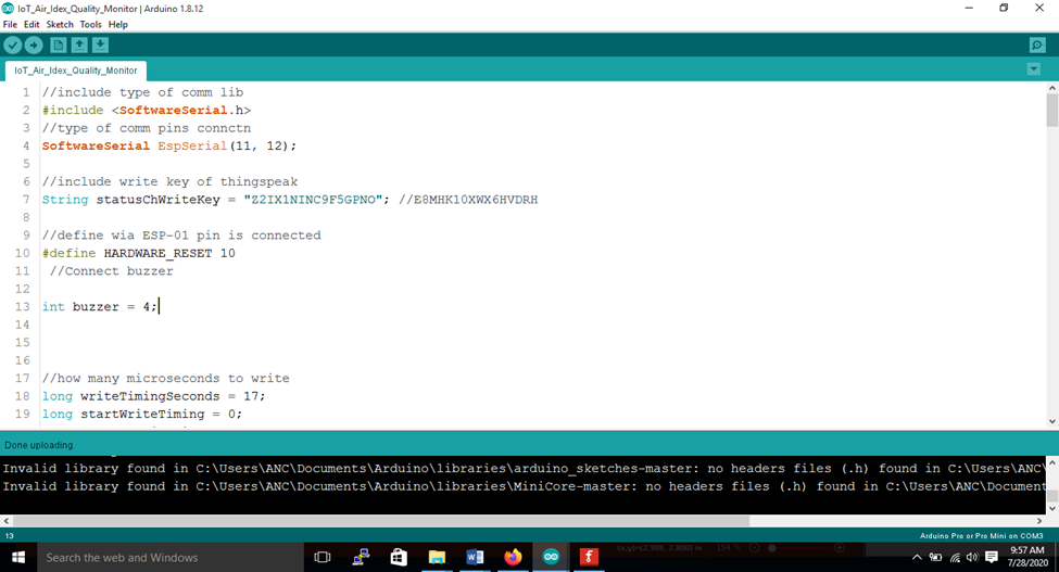
We began the setup() function and stated the baud rate for communication between the programming computer and Nano board to be 115200 bits per second. Before that, we declared and defined where we connected the buzzer alarm pin to be digital pin 4 on the Nano board. Some variables were declared to keep track of some changes in the readings of the gas sensors.
Testing and Calibration
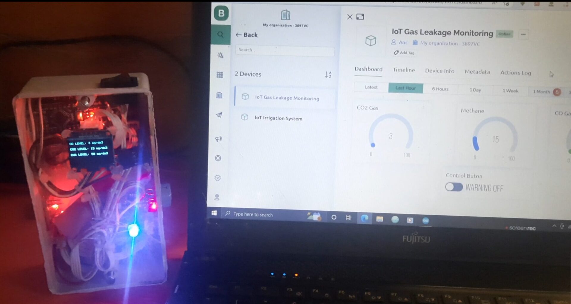
To test the gas leak detector with Arduino and Blynk IoT project, we exposed the hardware design to gas emmsion from a cooking gas cylinder. Once the gas started erupting, the MQ-2 gas sensor pictked up the smell and the design could be seen beeping a warning sound.
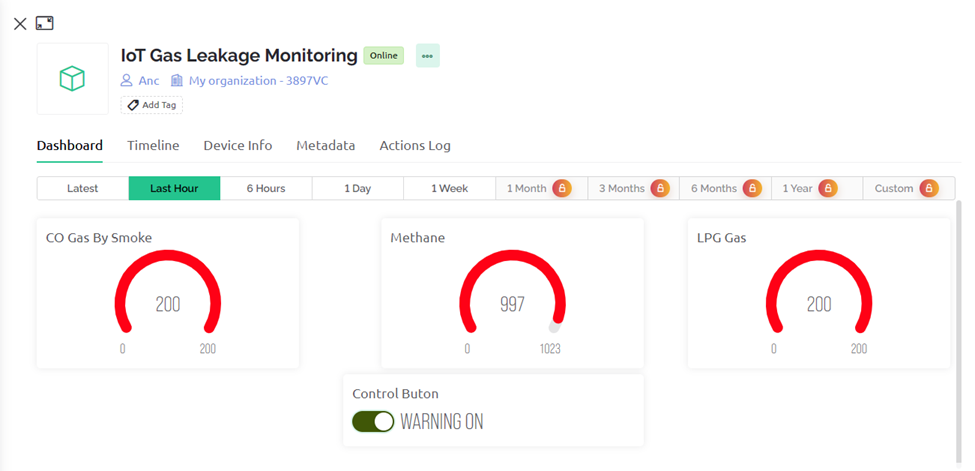
The OLED screen displayed alarming rate of gas level concentration and the IoT dashboard were towards the red part of the chart widget. There was also an in-app alert, telling us that the design has been exposed to alarming rate of gas concentration.
Safety Tips
Always follow safety guidelines when working with gas detectors and gas appliances. Regularly test and maintain your gas detector to ensure it is functioning properly.
Conclusion
Building a smart gas detector with Arduino such as this project is a simple and effective way to enhance the safety of your home. By detecting gas leaks early, you can protect your family and property from potential harm.
Share Your Project
Have you constructed an innovative Gas Leak Detector with Arduino and Blynk IoT on your own? Please share in the comments below your project setup, Blynk interface design, and any difficulties you encountered! We would be delighted to view your works of art and start a conversation among Arduino enthusiasts.
FAQs
What is a gas leak detector?
A gas leak detector is a device that detects the presence of flammable or toxic gases in an environment. They come in various types and can be used in homes, businesses, and industrial settings.
Why are gas leak detectors important?
Gas leaks can be dangerous and even fatal. Gas leak detectors can alert you to a leak before it becomes a serious problem, allowing you to take action to avoid an explosion, fire, or carbon monoxide poisoning.
What types of gas leaks can detectors identify?
Common gas leak detectors can identify natural gas, propane, carbon monoxide, and some other combustible or toxic gases. However, the specific type of gas a detector can identify depends on the model and sensor technology used.
Choosing and Using Gas Detectors:
What type of gas leak detector do I need?
The type of gas leak detector you need depends on the specific gas you are concerned about and the environment where you will be using it. It’s important to choose a detector that is designed for the type of gas you are trying to detect.
Where should I install a gas leak detector?
Gas leak detectors should be installed in low-lying areas near potential gas sources, such as kitchens, laundry rooms, and garages. Some detectors are portable and can be used to check for leaks in specific areas.
How often should I test my gas leak detector?
Most manufacturers recommend testing your gas leak detector monthly according to the manufacturer’s instructions. You should also replace the sensor in your detector according to the manufacturer’s recommended schedule.
What should I do if my gas leak detector goes off?
If your gas leak detector goes off, evacuate the area immediately and turn off the main gas supply valve to your home or building. Open windows and doors to ventilate the area. Call the fire department or a qualified gas technician from a safe location outside the building.
Additional Considerations:
Are there any limitations to gas leak detectors?
Gas leak detectors can be very effective in alerting you to a gas leak, but they are not foolproof. They may not detect every type of gas leak, and they may not work properly if they are not properly installed or maintained.
What are some alternatives to gas leak detectors?
There are no truly effective alternatives to gas leak detectors. However, you can take steps to reduce the risk of gas leaks, such as having your gas appliances serviced regularly and checking for loose connections.
Can I build my own gas leak detector?
While there are DIY projects online for gas leak detectors, it is generally not recommended. Commercially available detectors are more reliable and safer, especially for detecting potentially dangerous gases.

