Hello dear reader , in this tutorial we will be talking about using the Voltage Sensor Module to Measure Solar panel voltage level. The Voltage Sensor Module is a voltage sensing module that can be interfaced with an Arduino for measuring DC voltages within 2V – 25V. To read more about the technical details, go to shop.
Understanding how to accurately measure the voltage level of a solar panel is essential in solar power system design, testing and troubleshooting. One of the simplest and most reliable ways to achieve this is by interfacing a solar panel with an Arduino using a voltage sensor module. This project allows you to observe voltage behavior under different sunlight conditions, compare daytime output fluctuations, and protect your electronics by ensuring incoming voltage stays within safe tolerances. What makes this project especially valuable is that it provides real-time visual and serial feedback of your solar input, making it ideal for students, DIY beginners, and renewable energy enthusiasts who want to learn instrumentation and energy monitoring.
Components Used for Project Tutorial:
In this practical, we will be using the Following Component.
- Arduino Uno
- Voltage Sensor
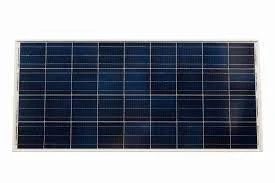
- Solar panel (21.5V)
- Jumper Wires
- Screwdriver
All these components can be bought on our online store. Alternatively, if you can’t find them, leave us a message on WhatsApp or Telegram group for assistance or in the comment section way down below.
To complete this tutorial, the primary items used include the solar panel serving as the energy source, an Arduino microcontroller functioning as the measurement and processing unit, and the voltage sensor module acting as the interface that allows the panel’s output to be safely read without overloading the Arduino pins. Supporting elements include wires, a breadboard to simplify and organize connections, and a laptop running the Arduino IDE for code uploading and serial monitoring. The components are selected specifically because they are easy to assemble, safe to operate, affordable, reusable across multiple projects, and effective in demonstrating basic principles of solar measurement systems.
Arduino Voltage Sensor Module: The Principle of Operation
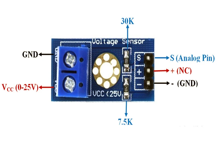
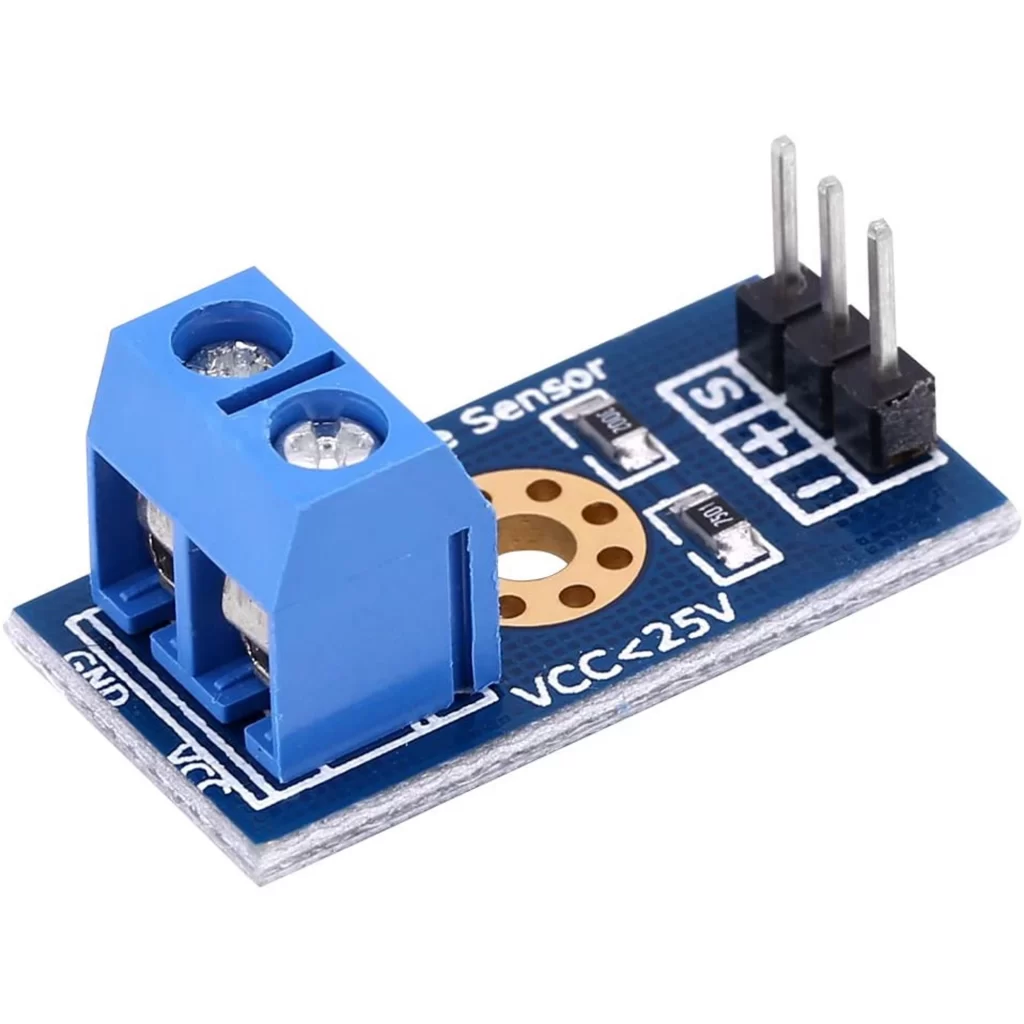
The Voltage sensors are made up of the following input pinouts (VCC and GND) socket – (which can take in Maximum Voltage of 25v). These pinouts are used for measuring the voltage. On the other side, it has 3 pins which contains (VCC, GND and S where S is the Analog pin that can be connected to Arduino).
The Arduino voltage sensor module works by taking a higher input voltage and reducing it to a lower scaled value that the Arduino can safely interpret. Internally, the module uses a voltage divider network consisting of precision resistors that proportionally lower the input voltage level based on a fixed ratio. This scaled-down voltage is then fed into one of Arduino’s analog input pins, where it is converted into a digital numerical value by the ADC (Analog-to-Digital Converter). Once the microcontroller receives this reading, software logic reconstructs the original voltage mathematically using the known scale factor of the module. The fundamental idea is that instead of directly connecting the solar panel to the Arduino, the voltage sensor provides safe isolation, monitoring accuracy, and ensures that even fluctuating sunlight peaks do not damage the board.
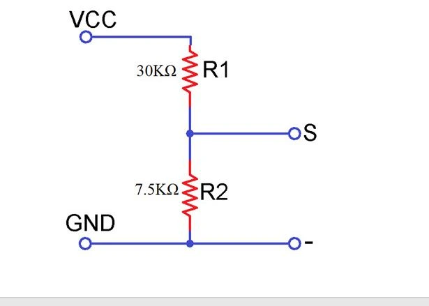
The Arduino Sensor Module contains 2 Resistors 30kΩ and 7.5kΩ that uses the principle voltage divider rule. This is given in the Equation as:

Read up more on this this link. Let us proceed to how to hook this up to an Arduino Uno board and use it to measure DC voltage from a Solar panel up to 24V DC.
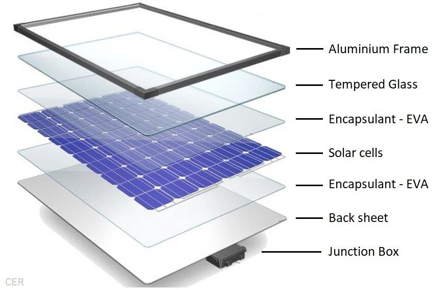
Solar Panels and How They are Made
Solar panels use photovoltaic cells, or PV cells, which are made using silicon crystalline wafers similar to the wafers used to make computer processors. The silicon wafers can be either polycrystalline or monocrystalline and are produced using several different manufacturing methods. The most efficient type is monocrystalline (mono) which are manufactured using the well known Czochralski process. This process is more energy-intensive compared to polycrystalline (poly) and therefore more expensive to produce.
Polycrystalline wafers, on the other hand, are slightly less efficient and are made using several purification processes followed by a simpler, lower cost, casting method. More recently, cast monocrystalline or cast mono cells have been gaining popularity. The reason is due to the lower-cost casting process used to make cast mono cells which is similar to the process used for polycrystalline silicon cells. However, cast-mono wafers are not quite as efficient and pure mono wafers made using the Czochralski process. The various types are namely:
- Monocrystalline silicon cells – Highest efficiency and highest cost
- Cast monocrystalline cells – High efficiency and lower cost
- Polycrystalline silicon cells – Lower efficiency and lowest cost
Read all about solar panels and how they are manaufactured here. However, for this tutorial our focus is to use Arduino Voltage Sensor Module to Measure Solar Panel Voltage level .
Voltage Sensor Module: Measure Solar Panel Voltage level
The Circuit Diagram
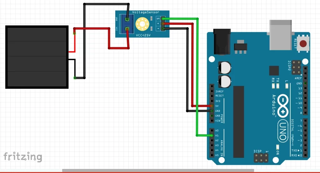
To use the Arduino Voltage Sensor Module with Arduino Uno board, the 3 pins of the Voltage sensors are connected to Arduino Uno as shown above. In which, the VCC is connected to 5V. The GND is also connected to the GND of the Arduino. The “S” which is the Analog pins slot is connected to the Analog part on the Arduino board, which could be connected to (A0, A1, A2, A3 and …). For this project we used the A1 analog pin on the Arduino Uno board. To read the battery level for a 3V battery, the above circuit was used.
The voltage sensor module connects to the solar panel output terminals so that the varying DC voltage created by sunlight can be monitored and analyzed. As sunlight increases, the solar panel generates higher voltage, which the sensor module scales down and sends into the Arduino for processing. The Arduino then analyzes the incoming analog signals and converts them into readable voltage values. This allows the real-time voltage level of the solar panel to be displayed through the serial monitor or an LCD if added. What makes this arrangement significantly useful is that it allows safe measurement without requiring complex test instruments. It also allows you to observe performance characteristics, such as stability, peak voltage, and response under shading. The voltage sensor module therefore acts as an intermediary bridge that simplifies the relationship between renewable energy hardware and the microcontroller software environment.
Voltage Sensor Module: Measure Solar Panel Voltage Level(Arduino Sketch)
Measuring the real-time voltage output of a solar panel using an Arduino and a voltage sensor module requires a stable code routine that continuously reads analog values, converts them precisely, and then reports them in volts. The role of the Arduino sketch here is not only to fetch values from the sensor, but also to interpret them, scale them accurately to match the sensor’s voltage divider ratio, and display them in a meaningful way—whether on the Serial Monitor, an LCD module, or transmitted wirelessly to a monitoring dashboard.
The sensor module typically provides the Arduino with a fraction of the actual solar voltage because the voltage divider inside the module reduces the incoming level into the safe analog-reading range. In the sketch, this divider must be accounted for in the calculation. This is where the calibration constant becomes extremely important. The Arduino receives raw ADC values (0-1023 on most boards), and the sketch interprets these readings against the module’s reduction factor. Without these calculations, the values would appear meaningless and inconsistent, especially when used under variable sunlight conditions.
In the code, the setup stage prepares the serial communication and initializes the pin used for reading. The loop stage continuously reads, processes, and prints updated voltage data. Some Arduino sketches include minor averaging techniques that stabilize noise that normally appears when sunlight fluctuates due to clouds or shading. A well-structured sketch compensates for this by applying a steady conversion ratio and returning real-time output without sudden spikes.
It is also possible inside the sketch to define an operational threshold, meaning the system can detect when the solar panel voltage falls below a specified A-level. This allows the Arduino to trigger external relays, alarms, or even automate a switching mechanism that protects batteries from under-voltage. The sketch can therefore serve not only as a data-monitoring tool but as a smart energy-management routine.
In a more advanced form, the measurement sketch can be extended into a data-logging system where voltage readings are stored with timestamps. From this point the same code can be merged with SD-card modules, IoT dashboards, or Wi-Fi upload functions that track solar performance throughout the day. The fundamental structure remains the same, but the sketch becomes more powerful by giving actionable insight into energy production trends.
So, the Arduino sketch serves as the interpreter between the voltage sensor module and meaningful human understanding. By transforming electrical values into readable voltage levels, the code makes the system usable by engineers, installers, and students who want a clear view of how their solar panel behaves across varying loads, temperatures and irradiance conditions.
Explanation of Source Code (Arduino Sketch)
float PVr1 = 30000.0;
float PVr2 = 7500.0;
float batteryVoltSensor, vinBattery;
const int voltagePinBattery = A0;

void setup() {
  Serial.begin(9600);
   Serial.println("Now in Setup");
Serial.println("Now exiting Setup function");
}

void loop(){
Serial.println("Now in loop function");

  //now doing calculations
  batteryVoltSensor = analogRead(voltagePinBattery);
 batteryVoltSensor = (batteryVoltSensor * 5.0)/1023.0;
 vinBattery = batteryVoltSensor/(PVr2/(PVr1+PVr2));

Serial.println(vinBattery);

Serial.println("Now exiting loop function");
 delay(1000);
}
The Arduino sketch is the same as the sketch used for measuring the various battery level voltages. You can take a look at it here. The sketch begins with declaring and assigning floating point variables that takes care of the values of resistors used to form the voltage divider rule. Other variables were declared to later compute the voltage of the PV (solar panel) measured. In the setup() function, the serial communication is began at a baud ate of 9600 bits per second, we printed out some dummy string text to know when we have entered the setup() function and have exited out of it.
In the loop() function, we carried out the calculation that measured the PV voltage. This was done using the analog pin where the Analog pinout of the Arduino voltage sensor was connected. Then this was multiplied by 5V since the Arduino Development board can take a maximum of 5V of logic voltage. Converted to to actual voltage when divided by 1023 for 16 bits microcontrollers.
The Arduino sketch programmed for this tutorial continuously samples the analog input pin where the voltage sensor module is attached. Through a mathematical relationship built into the code, the microcontroller converts the raw ADC value into a corresponding real-world voltage reading based on the module’s predetermined division ratio. The code keeps running and updating this value several times per second, allowing the user to observe even slight fluctuations caused by passing clouds or different solar orientations. The sketch also ensures that conversion accuracy is maintained through calibration factors written directly into the script, which refine measurement precision. The final computed voltage is then printed out through the serial monitor of the Arduino IDE, making observation effortless during indoor testing or outdoor data collection sessions.
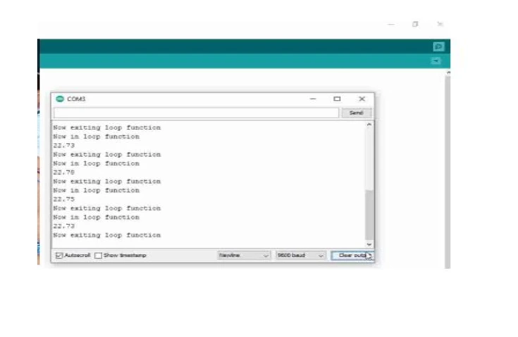
Results
Once powered and connected outdoors, the results show a direct correlation between sunlight intensity and the voltage reported by the Arduino. Voltage values rise during strong sunlight, remain moderate under partial cloud cover, and decline toward evening. Early morning readings appear low and gradually increase as the sun moves to a higher angle. These observations confirm the sensitivity of the panel and the reliability of the voltage sensor circuit in tracking real-time energy production shifts.
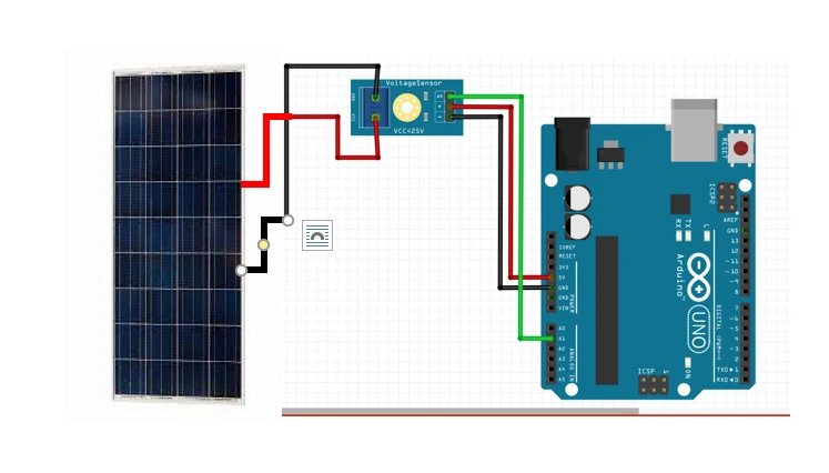
Explanation of Circuit Diagram
The circuit diagram for this 21V PV panel uses the same source code (Arduino Sketch) given above. The voltage level of the solar panel for this Arduino Voltage sensor module measure Solar panel voltage level project was observed to increase by up to 22V and it was printed out on a serial monitor.
The circuit diagram portrays how the solar panel terminals are linked to the voltage sensor input channel, while the module output pin is wired to Arduino’s analog port. Ground reference is consistently shared between the Arduino and the voltage module to stabilize signal flow. The purpose of the diagram is to visually clarify the electrical interaction between the solar generator and the microcontroller system. The layout prioritizes safety by ensuring the solar panel never connects directly to the Arduino analog pins, as that would exceed voltage tolerance. The diagram therefore provides the necessary guidance that ensures the connection style is correct, reliable, and electrically secure.
Conclusion
The serial monitor printing shows that we can measure or take the reading of various DC voltage levels of any solar panel that is within the range of 25V MAXIMUM using this voltage sensor. To take measurements above 25V, you have to see our other project tutorial. The readings obtained in this project would then be uploaded to a cloud dashboard using an Arduino Uno and an ESP8266-01 WiFi module.
So what do you think about this tutorial? Can you reproduce this? or make further modifications to it? Let us know if you tried it and how it built you in the comment section below.
Thank you.
Measuring the voltage level of a solar panel using a voltage sensor module and Arduino is more than just observing a fluctuating reading on a screen—it is a powerful process that helps you understand how effectively your panel is converting sunlight into usable electrical output. With a properly calibrated sensor module and a well-structured Arduino sketch, you can monitor daytime variations, detect efficiency drops, troubleshoot irregular charging cycles, and verify panel health in real-world conditions. Whether the goal is experimentation, academic research, or practical solar system maintenance, the process equips you with the insight needed to design better, safer, and more reliable renewable-energy projects.
As your familiarity grows, the same setup can evolve into automated protections, remote-monitoring systems, and long-term data analytics, turning a simple measurement into valuable engineering intelligence
Frequently Asked Questions (FAQs)
1. Can an Arduino measure a solar panel voltage directly without a sensor module?
No, the Arduino cannot measure high voltage directly. Solar panels often produce voltages far above the Arduino’s safe ADC input limit. The sensor module steps that voltage down safely before measurement.
2. Why does the sensor reading fluctuate during the day?
Solar voltage naturally varies with sunlight intensity, shading, panel temperature, angle, and load demand. The fluctuations are normal and reflect real operating conditions.
3. Does the voltage sensor module measure current as well?
No, the voltage sensor module measures only voltage. To measure current, you need a current sensor such as ACS712 or a dedicated shunt-based measurement module.
4. How accurate is the Arduino voltage reading?
Accuracy depends on module calibration, reference voltage stability, wiring quality, ADC noise, and calculation precision inside the code. It improves significantly with calibration.
5. Can this setup be used with larger wattage solar panels?
Yes, as long as the measured voltage remains within the maximum sensor input rating. Higher wattage does not affect measurement safety—voltage does.
6. Can the measured voltage be displayed on an LCD instead of the serial monitor?
Yes, the sketch can be modified to display readings on LCD, OLED, Nextion, or even wirelessly on IoT dashboards without changing the measurement principle.

