In today’s project design, we made a footstep to electricity project that focused on how to generate electricity using foot-steps with a backup charging station (Piezoelectric generator) project. We can use this to charge devices such as smartphones, tablets, and any 5V-rated rechargeable appliance. This foot-step power generation project is a typical example of an electricity generator tile project. And this tutorial goes further than just generating electricity using footsteps but adds a DC-based backup charging station with charging and full charging indicators. Ensure you read until the end to get a full grasp of how it was designed and built. Watch the full video demo here.
Project Materials/Components
Arduino Nano board Buy here
Piezoelectric transducer sensors buy here
LCD wire and connector sockets
10kΩ potentiometer buy here
USB connector
Bottle water caps
Some stranded 1mm wire
glue sticks buy here
Glue gun 20W
3” x 6 “ adaptable box
Wires
shrink tubes b
Chat and order for the complete kit of this here
Introduction
The piezoelectric sensors, also known as PZT ceramic sensors work on the principle of piezoelectric effect, which means that the sensors can convert mechanical stress (either pressure or stress) into electricity. Read more about this here.
The type of PZT ceramic sensors used for this project is shown below. The footstep power generation using piezoelectric sensors project won’t be possible without these PZT ceramic sensors. Each sensor has a pair of wires attached to it. The red-colored wire and the black wire. These should represent the positive and negative polarities of the sensor. However, this isn’t the case when in the piezoelectric generator circuit diagram.
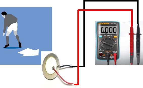
When mechanical stress (in the form of applied pressure or impact stress) is applied directly to any of the PZT ceramic sensors, it generates an AC voltage signal. This can be measured by the digital multimeter as shown above. A single piezoelectric sensor of this type can generate up to 6V under the right amount of mechanical stress. This was why this sensor was ideal for our electricity generation from pressure project design.
Assembling the Piezoelectric Sensors
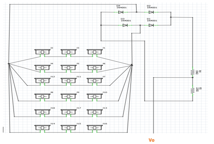
The best way to get the most out of the PZT sensors was to assemble or configure the piezoelectric sensors in a node analysis configuration. That is, both series and parallel in configuration. Having a total of 18 PZT ceramic sensors, the connections were made according to the circuit diagram below.
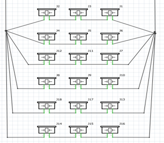
The circuit diagram for the foot step power generation system using piezoelectric sensors showed the connection of the PZT ceramic sensors was connected in both series and parallel modes. There were 3 serially placed PZT sensors, and each of these serial connections (rows) was in turn placed in parallel with 5 other rows of 3 series-connected PZT ceramic sensors. The reason for this mode of configuration was to amplify the voltage output in the series connection and the current in the parallel connection. The series connection of these sensors would increase the overall voltage. A series connection of 3 PZT ceramic sensors can output up to 25V AC when an even force is applied across the sensors. However, the series-connected PZT sensors are susceptible to having an “open circuit” when either of the PZT ceramic sensors breaks or fails during use. Each of these sensors in real life is fragile and can break if the applied pressure is not even around the surface. This means that the series voltage output won’t be realized because of one damaged sensor in the series connection.
By using a configuration of both series and parallel, we try to minimize this voltage loss such that, the rows not affected can still output voltage in this how to generate electricity using foot-steps with backup charging station (piezoelectric generator) project or advanced footstep power generation system.
Rectification and Filtration of the Alternating Current (AC) Voltage.
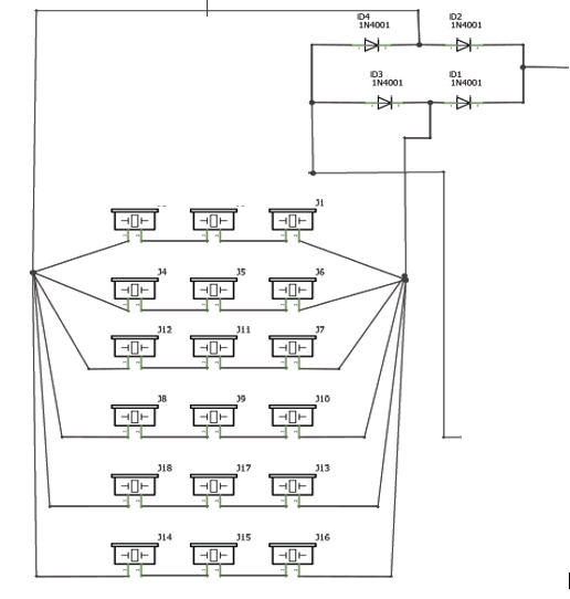
The output voltage of the piezoelectric generator is AC-based, and we intend to use it to power DC loads. To achieve this, the bridge rectifier was used to convert the AC signal to DC signal. The bridge rectifier component makes life easier than using the full wave configuration of 4 diodes. Once the rectification was done, further filtration of AC ripples was done using a 100µF 35V electrolytic capacitor.
Piezoelectric sensors naturally generate AC voltage, which must be converted to DC before it can charge a battery or power electronics. This is where the rectification stage comes in.
A bridge rectifier converts the alternating pulses into a smoothed DC output. However, the rectified voltage still contains ripples, so a large electrolytic capacitor is added as a filter to stabilize the voltage. This filtered DC power becomes the usable output for charging and storage.
Generate Electricity using foot-steps: Adding Backup battery
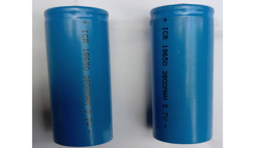
The generation of electricity using footstep project design needed a backup battery. This would serve as a backup when the piezoelectric generator was not producing voltage. This backup battery is made up of 3 pieces of 3.7V 3800mA LiPo batteries all connected in series. This battery configuration gave a resultant voltage of 11.1V.
Recharging Backup Battery.
To recharge the backup battery, a constant current charging method was used to recharge the backup battery. By practical measurement, the output of this piezoelectric generator circuit diagram was found to range from 10V to 15V. The voltage from the PZT circuit was connected through a current limiting resistor of 1kΩ which was then connected to the now 11.1V LiPo batteries.
Adding A DC Based Charging Station.
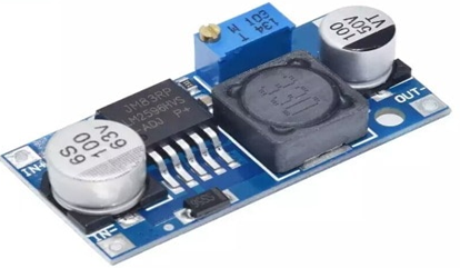
The piezoelectric generator has been able to generate DC voltage which can be used to recharge a DC battery that produces 11.1V. To use this voltage level for microcontrollers and DC charging ports; we needed to regulate and stabilize them to 5V. The module used for this job was the DC-DC buck converter. This module allowed us to step down the output of the backup battery to the 5V logic level for the Arduino Nano microcontroller board and the DC charging ports.
To make the system functional for everyday use, a small DC charging station is added. This station can include USB charging ports or a DC jack for powering portable devices.
The charging station draws energy from the backup battery, not directly from the piezo sensors. This guarantees stable and consistent output even when no one is stepping on the platform. It effectively turns human motion into a useful energy source for mobile gadgets, LED lights, or small electronics.
Generate Electricity using Footsteps: Arduino-Based Voltage Monitoring
The Arduino Nano board was used to measure and display the voltage output by the piezoelectric generator as well as measure and display the voltage level of the backup battery. The circuit diagram was connected as shown below.
The voltage measurement of this how to generate electricity using foot-steps with backup charging station (piezoelectric generator) project was done using the voltage divider rule; this is composed of a pair of known resistor values, R5 and R6, respectively, connected in a series connection. The measurement of the voltage generated by the piezoelectric generator was mostly the voltage drop across R5, as shown in the above circuit diagram. The Vo wire (also called the analog input wire) was connected to the analog pin A0 of the Arduino Nano board. However, because Arduino pins cannot withstand voltage levels above 5V, Caution was taken and a Zener diode of 5V was connected in the reverse direction in parallel to resistor R5. This would ensure that the maximum voltage drop across the Arduino analog pin was 5V.
Since power from footsteps is intermittent, a backup rechargeable battery is added to store the energy produced by the piezo layer. The battery acts as a reservoir, collecting all incoming power and delivering a stable output whenever needed.
This storage ensures that even if the walkway is not in continuous use, the system still holds enough energy to power small loads or charge gadgets later. The choice of battery depends on the expected output and usage—Li-ion, NiMH, or sealed lead-acid batteries can all be used.
To measure the voltage level of the LiPo battery, we used a similar technique. This time, only the values of the resistors connected in series were changed. Since the maximum voltage to be measured and displayed was 12V, Using the series connection of 30k and 7.5k; we formed a voltage sensor. And this is a voltage divider having a ratio of 5 to 1 voltage divider. Hence, there is a reduction by a factor of 5 for any input voltage. The schematic can be drawn below.
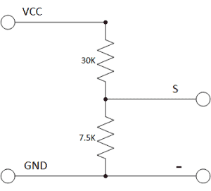
The voltage divider rule configuration of resistors that made up the LiPo Battery voltage measurement
Since we are reading the Arduino analog input pin, which accepts voltages up to 5V. But If the controller had a 3.3V system, the input voltage supplied to it should not be greater than:
3.3V × 5 = 16.5V
But Arduino came with AVR chips that have a 10-bit ADC architecture, so this setup simulates a resolution of:
0.00489V (5V/1023)
so the minimum voltage of the input voltage detection module is:
0.00489V x 5 = 0.02445V.
Light Emitting Diodes (LEDs):
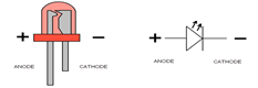
Also called Light Emitting Diodes, LEDs are diodes that convert electrical energy to light energy. The LEDs’ color types used here were Red and Blue LEDs. The Blue LED was to show an indication of charging while the red LED was used to show that the battery was full. However, in the video demonstration, only one LED was used to show when the DC charging port was ready to be used for charging. This red LED would indicate that power has been connected to the system.
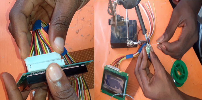
Adding LCD to the Project Design
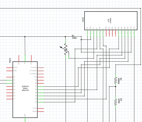
The LCD module was added to the circuit diagram as shown above; to make the how to generate electricity using foot-steps with backup charging station (Piezoelectric generator) project smarter. The LCD uses the 4-bit communication protocol. This means 4 wires were used for the Data transfer between the Arduino Nano board and the liquid crystal display (LCD) module. These four wire data started from Data wire 7 (D7) of the LCD through D4. The Register Select (RS) and the Enable (E) Pins of the LCD were connected to Digital Pin 2 and 3 respectively. A variable resistor of value 10kΩ was used to adjust the contrast display of the LCD. The variable resistor here was a potentiometer (pot). The wiper pin was connected to the A0 of the LCD. This means the Vcc of the 10 kΩ pot was connected to the 5V, and the ground pin was connected to the GND rail. The voltage drop across the pot is then used to determine the contrast brightness of the display module. Where the Vss and the Vdd pins of the LCD were connected to the 5V and Gnd rails of power respectively. To ensure the LCD came on looking bright, the LED+ and the LED- pins were connected to the power rails using a current limiting resistor of 10kΩ.
The Complete Circuit Diagram
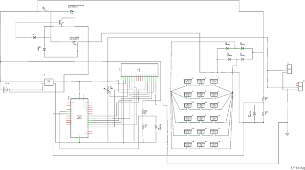
Download clear version of circuit diagram here
Explanation of the circuit diagram
The circuit diagram above added a charging indicator using a blue LED, as shown, as well as a full charge red LED indicator. The simple transistor configuration made this possible (although in the video demo, only one LED was used to show the system was ready to connect USB flex).
The circuit works in stages. The piezo discs form the input layer and feed AC voltage into a bridge rectifier. A capacitor smooths this voltage before delivering it to the battery. The Arduino taps into the battery output for monitoring, while the relay or regulator manages the charging station’s power delivery.
Each part performs a specific role:
- Piezo layer generates AC voltage
- Rectifier converts it
- Capacitor filters it
- Battery stores it
- Arduino, LEDs, and LCD display system activity
- Charging port outputs usable power
This layered approach makes the system efficient and easy to understand.
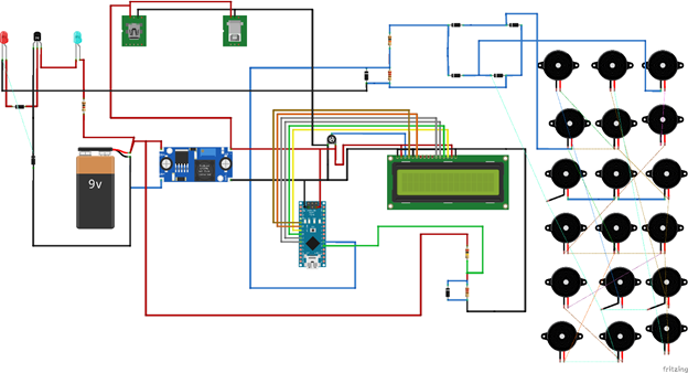
Assembling the whole Circuitry on A Veroboard
Using the Veroboard, we soldered the whole components that needed to be soldered on the Veroboard. The Veroboard type used is shown in the picture below. Things like the female header pins were soldered onto it.
Once the breadboard prototype is tested, the entire design is transferred onto a Veroboard. Components such as the rectifier, capacitors, voltage regulator, and Arduino connectors are soldered neatly into place.
This final assembly stage ensures durability and prepares the system for real-world use. Proper insulation and spacing are important here, especially where wires connect to the piezo elements or battery terminals.
The Perforated Board (strip boards or Veroboard) is a universal permanent circuit board. It is made of one side plastic perforated insulator used to arrange configurations of electronic design to finished work; and underneath, a copper plated line conductor that allows easy soldering. Before using this strip-board, our project was first modeled and tested on a Breadboard, which is a detachable platform, which gives room for error making, removal of components, and reattachment of the components. Unlike the Breadboard, the stripboard is used to solder these components together, and once done, is usually very difficult to remove them without applying heat or destroying the components by the use of force.
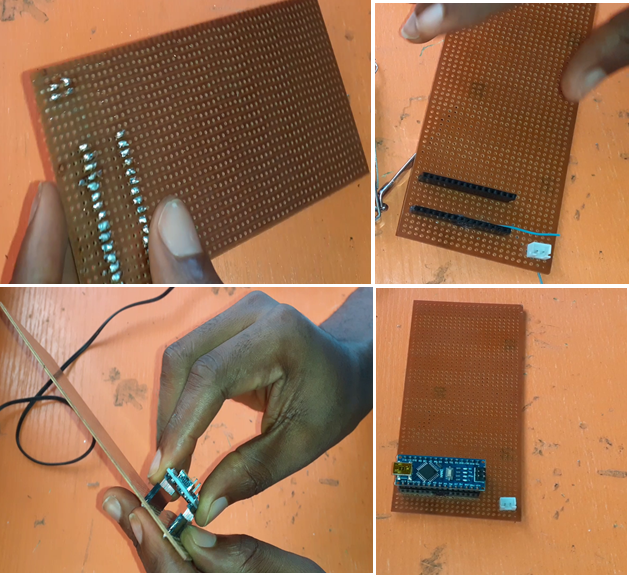
The soldering and the attaching of the Arduino Nano development board on the Veroboard. The LCD was connected using the LCD 16-pin wire terminal and female socket. This was then soldered to the Veroboard.
The Source code for the Design (Arduino Code)
// include the library code:
#include <LiquidCrystal.h>
#include <EEPROM.h>
#include <BigCrystal.h>
#include <BigFont.h>

// initialize the library with the numbers of the interface pins
LiquidCrystal lcd(2, 3, 7, 6, 5, 4);
BigCrystal bigCrystal(&lcd);

int volt;
float voltage1;
float divider = 0.936;
float piezoDivider = 0.26;
float multiFactor = 2.423;
float cell = 11.2;
float low = 3.2;
float full = 10.0;


void setup() {
  // set up the LCD's number of columns and rows:
  lcd.begin(16, 4);
   Serial.begin(9600);

 //write a welcome msg on lcd
 lcd.setCursor(2,1);
 lcd.print("...WELCOME...");
 lcd.setCursor(3, 2);
 lcd.print("  MR. TOLU ");
 delay(3000);
 lcd.clear();
 lcd.setCursor(4,0);
 lcd.print("FOOT-STEP");
 lcd.setCursor(2, 1);
 lcd.print("PIEZOELECTRIC");
 lcd.setCursor(3, 2);
 lcd.print(" GENERATOR");
 lcd.setCursor(3, 30);
 lcd.print("  PROJECT");
 delay(3000);
 lcd.clear();
   for(int x=0; x<16; x++){
  lcd.setCursor(0,0);
  lcd.print("Checking Battery  ");
  lcd.setCursor(x,1);
  lcd.print("*");
delay(200);
}
lcd.clear();
}


float checkBatVoltage() {

   volt = analogRead(A3);// read the input
  float voltage1 = (volt *5.273)/1023.999;
  voltage1 = voltage1/ divider; // divide by 100 to get the decimal values
  voltage1 *= multiFactor;


 float batPercent = map(voltage1, 3.41, 11.1, 0.0, 100.0);
Serial.print(batPercent);
Serial.println();
batPercent = constrain(batPercent, 0, 99);

     char buffer[5]; // buffer to hold the converted variable having a length that is +1 of the variable lentgh
     itoa(batPercent, buffer, 10);
     bigCrystal.printBig(buffer, 0, 0);
     bigCrystal.print("%");
     int number_count = 1;
    int number_temp = int(batPercent);
    while(number_temp != 0){
      number_count++;
      number_temp /= 10;
    }
    number_count-=1;
    if(batPercent < 1){number_count = 1;}
    lcd.setCursor(0 + (number_count*4), 0);
    bigCrystal.print(voltage1);
    bigCrystal.print("v  ");
    lcd.setCursor(1 + (number_count*4), 1);
     lcd.print(" BAT   ");


Serial.print("  Bat3 = ");
Serial.print(batPercent);
Serial.println("%");

  Serial.print("Batt Voltage: ");
  Serial.print(voltage1);//print the voltge
  Serial.print("V");

  Serial.print(" analogRead: ");
  Serial.println(volt);
  delay(500);
  return voltage1;


}


float checkPiezoVoltage() {
  int volt = analogRead(A2);// read the input
  float piezoVoltage = (volt *5.273)/1023.999;
  piezoVoltage = piezoVoltage/piezoDivider; // divide by 100 to get the decimal values
  piezoVoltage *= multiFactor;
  piezoVoltage *= 4.76;
  piezoVoltage = int(piezoVoltage);
  Serial.print("Piezo Voltage: ");
  Serial.print(piezoVoltage);//print the voltge
  Serial.print("V");

  Serial.print(" analogRead: ");
  Serial.println(volt);

 char buffer[5]; // buffer to hold the converted variable having a length that is +1 of the variable lentgh
     itoa(piezoVoltage, buffer, 10);
     bigCrystal.printBig(buffer, 0, 2);
     bigCrystal.print("V");
     int number_count = 1;
    int number_temp = int(piezoVoltage);
    while(number_temp != 0){
      number_count++;
      number_temp /= 10;
    }
    number_count-=1;
    if(piezoVoltage < 1){number_count = 1;}
    lcd.setCursor(0 + (number_count*4), 2);
    bigCrystal.print("  Piezo    ");
    lcd.setCursor(1 + (number_count*4), 3);
    lcd.print(" Gen     ");

return piezoVoltage;

}


void loop() {
  checkBatVoltage();
  checkPiezoVoltage();
  // set the cursor to column 0, line 1
  // (note: line 1 is the second row, since counting begins with 0):

  if(Serial.available())
  {
    char cal = Serial.read();
    if(cal == '+' || cal == 'a')
      divider += multiFactor;
    else if(cal == '-' || cal == 'z')
      divider -= multiFactor;
  }
   delay(50);
}

long readVcc() {
  long result;
  // Read 1.1V reference against AVcc
  ADMUX = _BV(REFS0) | _BV(MUX3) | _BV(MUX2) | _BV(MUX1);
  delay(2); // Wait for Vref to settle
  ADCSRA |= _BV(ADSC); // Convert
  while (bit_is_set(ADCSRA, ADSC));
  result = ADCL;
  result |= ADCH << 8;
  result = 1126400L / result; // Back-calculate AVcc in mV
  return result;
}
Explanation of the code

The syntax uses special libraries of LCD to display the generated level. Some variables that are universal variables to the code were defined above the setup() function and later used in the function to measure the generated voltage checkPiezoVoltage().

In this function, we read the analog voltage from the Vo and then converted it. This is the allowed 5V of the Arduino and the 10bits of the reading. Further calculations were done to adjust and make the reading close to accurate. These readings are then mapped using a map() function. This would allow us to display the voltage at a segmented level. The readings are then printed on the LCD screen using code lines 55 through 59. To make the function repeat itself; we placed the function itself in the loop() function. The loop() function repeatedly executes any code placed inside it.
Measuring the Battery Level Voltage

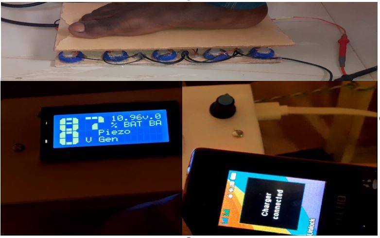
Results
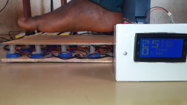
The results obtained are given in the diagram above. Here as seen, before we depressed the voltage generated by the piezoelectric generator was 0V but upon depressing the piezoelectric generator using our feet, we get about 10V DC or above. This voltage is displayed as generated by the piezoelectric generator.
DC-Based Charging Station
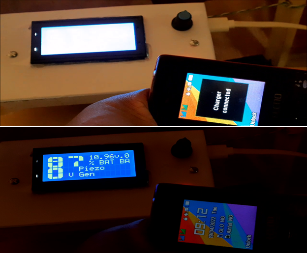
This was handled by the USB ports shown in the circuit diagram above. Once, any of these ports were connected to a USB charging flex, and connected to a phone. It keeps charging and this result is shown below. As shown in the picture above, the battery level was at 87% and at 10.96V, whereas the piezoelectric generator was at 0V. This was done by the programming sketch written above.
Conclusion
And that would be all for this how to generate electricity using foot-steps with backup charging station (Piezoelectric generator) project design. Let us know if you were able to create something similar or better. Don’t forget to leave a comment if you encounter any challenges along the way.
Thank YOU!!!


hi there im very interested in your project but the only thing i can’t understand is why you have a 5:1 ratio divider to measure the battery charge.
I will be glad if you can answer me that.
Have a nice day
Hi Perdro, The resistor turn ratio is for measuring the charging voltage for the microcontroller because the Atmega328P-PU has a voltage of 5V maximum.
Thank you very helpfull! can you tell me the value of zener diode exiting from transistor base and why you chosed that one? theres no info about that, have a nice day
Thanks very much Pedro, for your information and I learned a lot