Hello everyone. In today’s project tutorial, Automatic and Remote Control Pedestal Fan Arduino (smart fan), we will be answering the following questions.
Have you ever wondered if you could turn your home-standing fan into a smart fan?
Do you want to be able to control your pedestal fan using a remote control? perhaps add a display screen?
Do you want to see the temperature of your room displayed on this fan? Or perhaps you want to use the room temperature to control the speed of the fan?
Won’t it be awesome to reverse engineer your pedestal fan and build an automatic and remote control pedestal fan Arduino (smart fan) that would use the room temperature in the room to automatically control the speed of the fan and then lets you control the fan speed at your own will with just any remote control lying around?
Well, it is very possible and we will do this project tutorial today. Well stay tuned and ensure you read to the end because in this tutorial: we will be discussing how to achieve all of these functionalities inside the automatic control fan. But first, a brief introduction.
What is a Pedestal Fan?

This is an electric and oscillating fan supported by an adjustable, detachable stand with its head above the surface and is adjustable. The sole function of this is to circulate cool breeze around our room. The downside of this electrically powered fan is that its speed regulator control is manually operated.
What Is Home Automation?
Home automation is a step toward what is referred to as the “Internet of Things,” it is fun to build and easy if you have the right tools. Home automation is an aspect of IoT called domotics. There are a plenty variety of home automation systems that are available out there and these are equipped with making one’s life easier and more comfortable. Some popular home automation systems include:
-A home security system that is responsible for monitoring your home and will send out alerts if there is an issue, like a broken window or a theft
-An energy management system also helps in saving money spent on energy consumption by simply turning off the devices when they are not in use and adjusting the temperature regulators like thermostats.
-A home entertainment system that can allow one to control his/her home’s lighting, music, and television from any location. These and so many others.
However, for this project tutorials, our focus is the use a traditional standing fan, a temperature sensor, an Arduino board (standalone version), a TV remote, and other modules to build a smart fan that can measure accurately the temperature of the room, control the speed of the fan in “Auto Mode” using this temperature ranges while offering the user the choice to still override this using a TV remote control to set their own fan speed. Enough said already; let’s dive into designing the project.
Components parts for Automatic and Remote Control Pedestal fan Arduino (smart fan)
- Power Supply rated 5V, ≥ 2A or you can build your own here
- Atmeg328p-pu microcontroller
- 16MHz crystal oscillator (Newark part number 16C8140)
- 10nF capacitors
- A 10kΩ pull-up resistor
- A reset push button.
- Dallas temperature sensor DS18B20, maxim part number, 1534C4:
- A 4.7KΩ pull-up resistor
- Infrared receiver TSOP1738
- IR remote controller or any old TV remote(that’s an IR Transmitter)
- 560Ω 5-band resistor
- 1µF ceramic capacitor
- Generic jumper wires: male and female type.
- 16 × 2 Liquid Crystal Display
- 10KΩ potentiometer (trimmer)
- 56OΩ precision resistor
- LCD connector wires’
- Header pins
- 5V 4-channel Relay Module
- A standing fan
What is an Infrared (IR) Signal and an IR Receiver Module?
Infrared radiation that produces Infrared signals or radiations (IR) are actually beams of light, it is that portion of the electromagnetic spectrum that extends from the long wavelength, or red, end of the visible-light range to the microwave range. Invisible to the eye, it can be detected as a sensation of warmth on the skin. Most of the radiation emitted by a moderately heated surface is infrared; it forms a continuous spectrum. Molecular excitation also produces copious infrared radiation but in a discrete spectrum of lines or bands. Everything which produce heat, emits infrared like our human body. Infrared have the same properties as visible light, like it can be focused, reflected and polarized like visible light. IR devices are those photonic components that contains semiconductor materials that are sensitive to IR radiations. They are divided into IR transmitter Light Emitting Diode (LED) and IR Receivers.
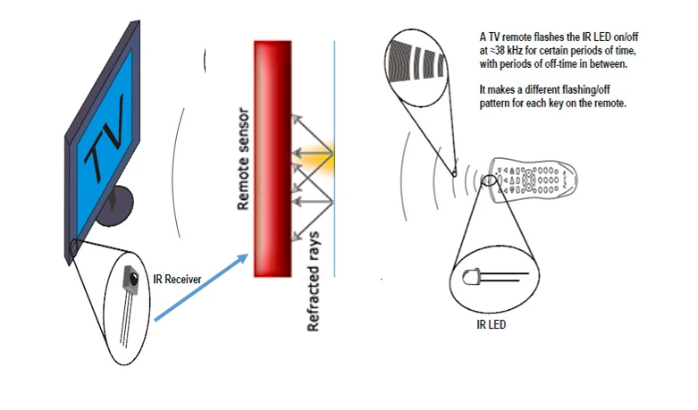
IR receiver is a sensor that is responsible for capturing the IR signal sent out by the IR emitter or in the case of this project the home TV remote. This exact part used here is shown in the component list to be the common TSOP1638. It has 3 pinout configuration and can be used either with a programmable device or non-programmable device. In this Automatic and Remote Control Pedestal fan Arduino (smart fan) project, it is used with a programmable microcontroller Atmega328P chip.
Configuring the IR Receiver Using Arduino.
The IR Receiver TSOP1738 pinout
This component as earlier mentioned, is the famous infrared receiver TSOP1738 that has three terminals with the Pin 3 connected to the HIGH of the PSU (+5 Vcc) supply and the Pin 2 connected to the ground terminal(or LOW) of the PSU while the Pin 1 is the output pin. It is called the data pin (or terminal) Do. To stop the sensor (TSOP1738) from sending fluctuation signals to the MCU due to IR impulses from random sources, a very low capacitive capacitor is connected from the data pin to the ground. This is between 100nF to 33µF. This is shown below.
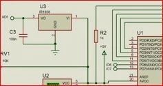
Decoding HEX Value Codes From the IR Receiver on Automatic and Remote Control Pedestal fan Arduino (smart fan) project.
Since this project isn’t based on a non-programmable Remote Control Home Appliance, there is a need to show the IR signals received by the Arduino on the serial monitor. The connection is shown above and the components are assembled on a breadboard.
A Brief Explanation Of Hex Codes.
The Decimal number system is also known as Base 10, since it’s comprised of ten numerals (symbolized by 0 through 9). Although we can only represent up to the number 9 by a single decimal digit, it’s possible to reference up to ten items by using zero ( 0) as an index to refer to the first ( 1st) item; thus, the numeral 9 would refer to the tenth ( 10th) item. With two digits we can refer to 100 items (zero through 99). In terms of the number of digits, 10 n (where n is the number of digits) equals the maximum number of items we can refer to. Therefore, the decimal equivalent of the largest binary number we can represent in 6 bits ( 111111 ) can be found as the sum of the first six powers of 2; starting with 2 to the power of zero (2 ^0): 20 + 21 + 2 2 + 23 + 24 + 25 = 1 + 2 + 4 + 8 + 16 + 32 = 63.
Or, by simply using the formula: 2n – 1 = 64 – 1 = 63.
To convert any binary number to hexadecimal, that is, base 16, simply order the bits into as many four-bit groups as possible, from the least significant position to the most significant position with any remaining group of only 3, 2, or 1 bits at the far left. Then convert each group to a single hex digit of 0 through 9 or A through F . So, to convert our 6-bit number of 111111 (63 decimal) to hex, we simply group the bits as: 111111 which is easily converted to: 3F hex. An 8-bit or 1-byte hexadecimal number can contain a maximum value of 255 decimal. A 10-bit binary number cannot exceed: 11 11111111 or 3FF or 1023 decimal. But, the maximum number of Cylinders we can reference in 10 bits is 1024, since we begin counting from zero.
A 32-bit unsigned integer value can be from 0 to 2(32-1). That is, from 0 to 2147483647. Similarly, 64-bit unsigned integer value can be from 0 to 2(64-1). Now, 32-bit hex value can be from 0 to 0x7f f f f f f f There will be only 8 digits i.e. 7 f f f f f f f because 1 digit corresponds to 4 bit. Hence 8 digits correspond to 8×4 = 32 bits. So, this means the digits which are followed by 0x are hexadecimal. There are two important aspects to the beauty of using Hexadecimal with computers: First, it can represent 16-bit words in only four Hex digits, or 8-bit bytes in just two.
Program Code to Decode the IR Signals off the Remote Controller
//include the IR remote library
#include <IRremote.h>
//state the IR input to the MCU
#define RECV_PIN A1
//make it recognised to IR Lib
IRrecv irrecv(RECV_PIN);
//ask it it get results and save it
decode_results results;

void setup() {
 //enable the IR
  irrecv.enableIRIn();
}

void loop(){
if(irrecv.decode(&results))  {
     irrecv.resume();
    //print the remote results in HEX codes
     Serial.println(results.value, HEX);
  }
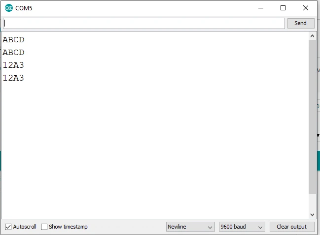
Wit the above program we can use the HEX code of each button to do a certain function on the speed control of the Alternating Current (AC) fan. These HEX value codes would be assigned in the program function later.
Reverse Engineering The AC Fan Control.
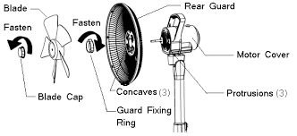
Steps to Reverse Engineeer Pedestal fan to Automatic and Remote Control Pedestal fan Arduino (smart fan):
Step 1:
Remove the fan blade cover. As shown above. The type of AC fa then used in this project has to be opened from the front side.
Step 2:
Remove the Fan blades and the locate the screws holding the speed regulator back casing.
Step 3:
Unscrew the screws holding the control head cover.
Step 4:
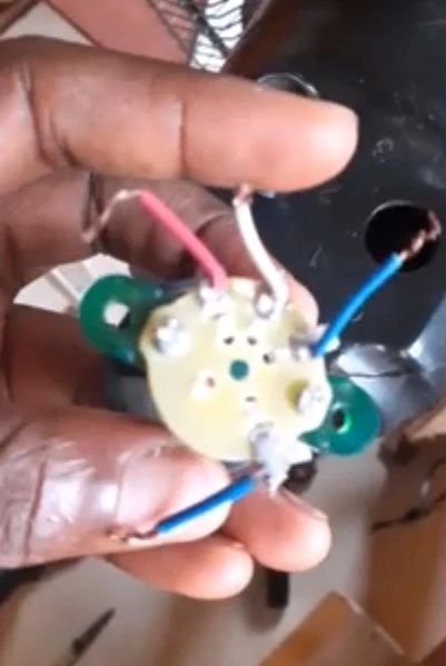
Remove the regulator knob and the back cover to locate the AC fan coil and the regulator panel. This is the only thing we want to mess with. The speed control knob has 4 input wires going into the coil of the . These are the speed 1 wire, the speed 2 wire, the speed 3 wire, and the neutral wire. These wires are to be connected to a relay module to allow automatic switching between each user button select to the appropriate coil connection terminal.

The Circuit Diagram for Automatic and Remote Control Pedestal fan Arduino (smart fan)
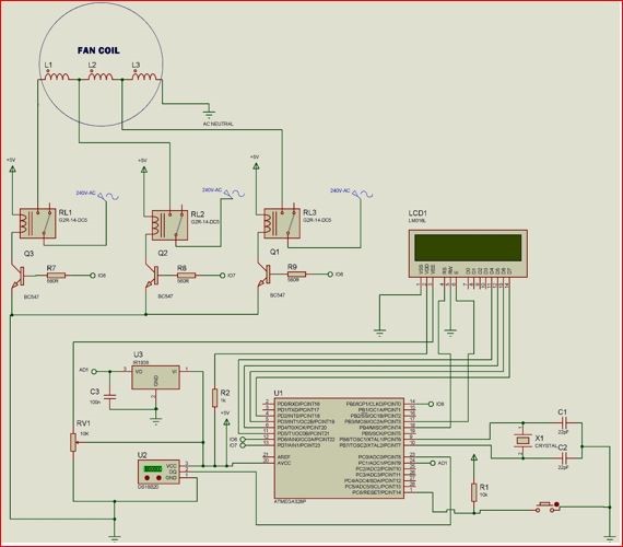
Explanation of Automatic and Remote Control Pedestal Fan with Arduino (smart fan) Circuit Diagram
As shown above, the circuit used temperature sensor DS18B20 to set for the automated mode for the pedestal fan speed control. The temperature sensor is connected in such a way it used a digital pin on the Atmega328P chip (Arduino Standalone) MCU. The temperature sensor uses 5V and this was ensured it was connected to the correct rated power rail. an enlarged section of the connection is shown below thus:
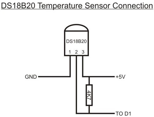
You can choose to connect your data pin of the temperature sensor to any of your microcontroller pins of your choice, whether analog or digital. Just be sure to define it in your source code. It is also very important to add the 4.7kΩ pullup resistor. If this connection were omitted, the temperature sensor wouldn’t work and the displayed readings would be confusing, like -127°C on the serial monitor window or LCD.
The relay module is an arrangement of a electromagnetic switches and other discrete linear components that can sense very minimum current input and allow a high voltage to flow across its switch. The module as shown below is designed with an optocoupler which is made up of LED and phototransistors; signal diodes for relay protection, general purpose NPN transistor and low value resistor.
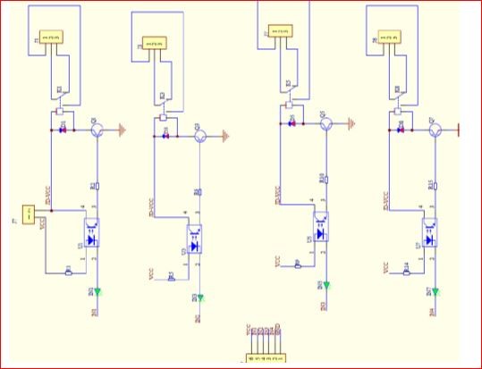
The relay module has four relays that works on the following operation: if we consider the first relay, having switch K1, the anode of the LED in the optocoupler is connected to the +5v Vcc through a resistor R1. Also the Collector of the transistor Q1 is given a +5v having a common emitter connection to baise the coil of the relay. Current would flow through the anode of the LED and it would glow (although this was not seen since it was encased) thereby biasing base of the transistor which would then conduct, allowing current to flow through the Vcc at the collector and since the base of Q1 is already open through R2 to the -5v(ground). This would in turn energize the coils of the K1 and the pole would change from terminal 3((Normally closed, NC) to terminal 1 (Normally Open, NO) of the Relay. The other relays K2, K3 and K4 works on the same operation.
Connecting the 1602 LCD Module:
The liquid crystal display is a display module programmable, economical and can display special characters. A 16×2 LCD means it can display 16 characters per line and there are two of such lines. Each character is displayed in 5×7 pixel matrix. The LCD has two registers namely; Command and Data. The pins and their functions are explained as:
Register Select (RS): this pin selects Command register when low and Data register when high. Read/Write (R/W): this pin writes to the register when low and reads from the register when high. Enable (E): this pin sends data to the Data pins when a high to low pulse is given to it. Pin 7 to 14 (D4 to D): these are 8-bit pins that are used to send and and receive data to/from the LCD. Pin 15 ( ): this is the positive (+Vcc) backlight of the LED (LED+) of the LCD. This pin is usually connected with a pullup resistor ( ≤ 1kΩ). this is important to limit current flowing in the LEDs of the LCD. Pin 16 (D16): this is the negative (ground ) −−Vcc pin. It is connected to the ground of the DC power supply.
Arduino Sketch
#include <LiquidCrystal.h>
//state which pins of the MCU connected 4 LCD
LiquidCrystal lcd(12, 11, 5, 4, 3, 2);
#include <OneWire.h>
#include <DallasTemperature.h>
#include <IRremote.h>
//state where the input of the temp sensor is connected
#define ONE_WIRE_BUS A0
int led1 = 6;
int led2 = 7;
int led3 = 8;
//set the OneWire lib to comm with other bus
OneWire oneWire(ONE_WIRE_BUS);
//transfer the data to Dallas temp Lib
DallasTemperature sensors(&oneWire);
//state the IR input to the MCU
#define RECV_PIN A1
//make it recognised to IR Lib
IRrecv irrecv(RECV_PIN);
//ask it it get results and save it
decode_results results;
void setup() {
   //begin the LCD to start displaying
  lcd.begin(20,4);
   //enable the IR
  irrecv.enableIRIn();
  //begin the temp sensor
  sensors.begin();
  //outline the inputs and output pins
pinMode(led1, OUTPUT);
pinMode(led2, OUTPUT);
pinMode(led3, OUTPUT);
//Serial.begin(9600);
//Display a welcome note
lcd.setCursor(0, 0);
lcd.print("Welcome Chinny!");
lcd.setCursor(0, 1);
lcd.print("Smart FAN Project");
delay(3000);
lcd.setCursor(0, 1);
lcd.print("Please Wait.......");
delay(2000);
lcd.setCursor(0, 1);
lcd.print("Smart FAN Ready");
delay(1000);
}
void SPEED1()
{
       digitalWrite(led1, HIGH);
       digitalWrite(led2,LOW);
       digitalWrite(led3, LOW);
       lcd.setCursor(0, 1);
       lcd.print("FAN AT SPEED 1 ");
      //Serial.println("FAN AT SPEED 1");
 }
void SPEED2()
{
      digitalWrite(led1, LOW);
      digitalWrite(led2,HIGH);
      digitalWrite(led3, LOW);
      lcd.setCursor(0, 1);
      lcd.print("FAN AT SPEED 2 ");
      //Serial.println("FAN AT SPEED 2");
 }
 void SPEED3()
 {
      digitalWrite(led1, LOW);
      digitalWrite(led2,LOW);
      digitalWrite(led3, HIGH);
      lcd.setCursor(0, 1);
      lcd.print("FAN AT SPEED 3 ");
     // Serial.println("FAN AT SPEED 3");
 }
 void fan_off()
 {
      digitalWrite(led1, LOW);
      digitalWrite(led2,LOW);
      digitalWrite(led3, LOW);
      lcd.setCursor(0, 1);
      lcd.print("FAN TURNED OFF! ");
      //Serial.println("FAN TURNED OFF");
 }
void tempSensor() {
  if(irrecv.decode(&results))
  {
     irrecv.resume();
    //print the remote results in HEX codes
     //Serial.println(results.value, HEX);
  }
  sensors.requestTemperatures();
  float roomTemp = sensors.getTempCByIndex(0);
  lcd.setCursor(0, 0);
  lcd.print("ROOM TEMP:");
  lcd.setCursor(10, 0);
  lcd.print(roomTemp);
  lcd.setCursor(14, 0);
  lcd.print("'C");
  if( roomTemp < 20.00 )
    {
      fan_off();
    }
   else if(roomTemp >= 20.01 && roomTemp <= 30.00)
    {
      SPEED1();
    }
   else if(roomTemp >= 30.01 && roomTemp <= 35.00)
    {
      SPEED2();
    }
   else
    {
      SPEED3();
    }
}
void remote()
{
     if(results.value == 0x1266897)
     {
      SPEED1();
     }
     else if(results.value == 0x1269867)
     {
      SPEED2();
     }
     else if(results.value == 0x126E817)
     {
      SPEED3();
     }
     else if(results.value == 0x12618E7)
     {
     fan_off();
     }
     else if(results.value == 0x126926D)
     {
      tempSensor();
     }
}
void loop() {
  sensors.requestTemperatures();
  float roomTemp = sensors.getTempCByIndex(0);
  lcd.setCursor(0, 0);
  lcd.print("ROOM TEMP:");
  lcd.setCursor(10, 0);
  lcd.print(roomTemp);
  lcd.setCursor(14, 0);
  lcd.print("'C");
  // Serial.print("ROOM TEMP: ");
  // Serial.print("  ");
  //Serial.println(roomTemp);
if(irrecv.decode(&results))
  {
     irrecv.resume();
    //print the remote results in HEX codes
     //Serial.println(results.value, HEX);
  }
     if(results.value == 0x126926D)
     {
        while((results.value == 0x126926D) ||((results.value != 0x1266897) && (results.value != 0x1269867) && (results.value != 0x126E817) && (results.value != 0x12618E7) && (results.value != 0x126926D)))
        tempSensor();
      }
       remote();
 delay(50);
}
Explanation of Arduino Sketch for Automatic and Remote Control Pedestal fan Arduino (smart fan) Project
The algorithms programmed into the microcontroller unit (MCU) chip, has two objectives:
First, the Auto Mode: if, say the room temperature is too hot, it would switch to a speed on the pedestal fan that is the highest speed. this would make the room cold and cozy. However, if it is cold, it would switch to a speed level that is comfortable or turn off totally if it is too cold.
The User Mode: Mostly, if the user feels that he or she doesn’t like the speed of the fan, he or she can pick up a remote control and select the desired speed of choice; giving it a user enable option.
The program records and stores the IR signals as HEX Values and it used only Hexadecimal to display the actual Binary bytes of a Memory Dump rather than a huge number of ones and zeros! The second aspect is closely related, whenever it is necessary to convert the Hex representation back into the actual Binary bits, the process is simple enough to be done. For example, FAD7 hex is 1111101011010111 (F=1111, A=1010, D=1101, 7=0111) in Binary.
Once the IR receiver was configured correctly as drawn in the circuit drawn above and this is powered on; using an old home TV remote as IR transmitter, specific button’s HEX codes were selected and mapped as commands into the MCU to control the fan speed controls. For example, for Speed 1, 0x1266897 is used. But inputting it in an if statement, it makes the MCU know which remote button controls what speed and which function.
Conclusion
This remote controlled fan facilitates the operation of fan regulators around the home or office from a distance. It provides a system that is simple to understand and also to operate, a system that would be reliable and easy to maintain, and durable irrespective of its usage. It adds more comfort to everyday living by removing the inconvenience of having to move around to operate a fan regulator. Automatic and Remote Control Pedestal Fan with Arduino (smart fan) is designed with an in-built temperature sensor module that measures the room temperature of the room at every time. It then regulates the fan speed controls based on this temperature in the automatic mode.
Do you think you can make such a project design? Let us know how you were able pull off such project in the comment section below.
You can watch the video of the YouTube link below to see the demo of the project in action.

