Ever wished you could open your gate without stepping out of your car?
Imagine driving home on a rainy day, pressing a button, and your gate slides open like magic. That’s the beauty of a Remote Gate Opener DIY project. It gives you comfort, security, and that futuristic vibe — without spending huge money on commercial systems.
The good news?
You can build one yourself. Yes, you. And it’s easier than you think.
Whether you’re a beginner in electronics or a seasoned DIY lover, this guide walks you through everything you need to know. No complicated jargon. No confusing diagrams. Just a simple, clear, and practical explanation of how to create your own remote-controlled gate opener.
How It Works
Let’s break it down in plain language.
- You press a button on the remote.
- The remote sends a wireless RF signal.
- The receiver picks up the signal.
- The relay switches ON.
- The motor runs and moves the gate.
- Limit switches stop the motor when the gate reaches its destination.
It’s simple, efficient, and works reliably.
Components Needed
- Atmega328P-PU
- 16Mhz Crystal oscillator
- L293D motor driver IC (or Module)
- Pushbutton
- 100nF caps (2 pcs)
- Male and female header pins
- 22pF caps (ceramic types, 2 pcs)
- LEDs (red and green colors)
- 10k ans 1k precision resistors
- 16×2 LCD module, socket headers and wire
- 10k potentiometer
- MP3 car remote control
- Pair of DVD/CD ROM
- Infrared Obstacle Avoidance Sensor Module
- Infrared (IR) Receiver TSOP1838
Buy All components on our online store
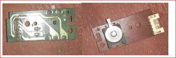
Motor-Driven Mechanism (Gating system)
This is made up of CD tray, DC motor and drive belt from an old DVD player machine.
The low cost nature and its availability made it very useful in its selection. We used two of these devices to control the closing and opening of the gate system. The amazing part of these devices is that each mechanism has a “stopper switch” buried beneath the tray that moves to cut power to the DC motor driving the drive belt that in turns moves the tray. This stopper switch’s state changes in any direction it moves. When it is full forward direction, the stopper switch is LOW and when it is full reverse direction, the switch moves to HIGH. We used these change in states to control our gating system
Also, the drive belt between the DC motor and the gears that control the CD tray doesn’t maintain a very firm grip on the both gear and DC motor. This is very good so that once the tray has gotten to the marked position and by some reasons unknown, the DC motor is still power, the immovable action on the tray won’t cause the DC motor to get over heated and burn out.
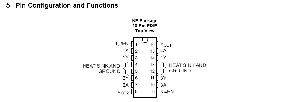
Using L293D Motor Driver IC for Remote Gate Opener Project
This integrated circuitry makes it very possible for us to control the motion of the gating system (which involves two DC motors) simultaneously. The L293D is a device that is quadruple high current half-H drivers. With bidirectional drive currents up to 1A at voltages from 4.5V to 36V. This makes it ideal for relays, solenoids, DC and stepper motors.
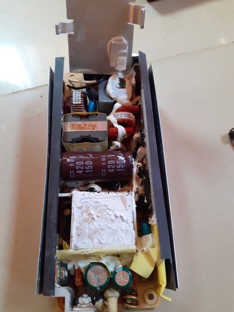
The Power Supply: The power supply used in this project design was a switch mode power supply. The choice was due to its consistency in supply output the required voltage demanded from it at the specified current rating.
Infrared Obstacle Avoidance Sensor Module: The infrared obstacle avoidance sensor is made up of two infrared LEDs. One is used as the transmitter, while the other is the encapsulated receiver. These two IR sensors are soldered on the same PCD board that has an adjustable potentiometer.
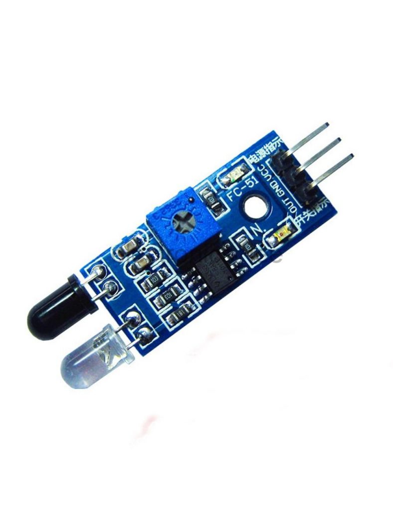
The two sensor LEDs are controlled by an on-board comparator LM358 which compares the threshold between the inputs of the IR LEDs. The potentiometer used here was to adjust the sensitivity of the IR receiver. The IR obstacle avoidance sensor module works thus: The transmitter (usually the bright encapsulated LED) emits IR signal and once there is no obstacle in its path, the receiver doesn’t get to receive it. But if there is an obstacle in the transmitter’s line of sight, the signal bounces off the obstacle and echoes back to the receiver through diffraction and reflection. Once the receiver LED receives this signal, it activates the signal received active on-board LED to indicate that it has received the signal and it will automatically change the signal output on its board (which is HIGH, giving 1) to LOW, producing 0).
IR Receiver TSOP1838:
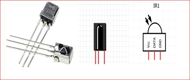
This IR receiver operates at 38KHz frequency and can decode the IR signals sent to it from the remote controller. The pinout diagram is shown above. The IR receiver, however, when tested with non-programmable chips, shows some inconsistent signal received due to its data pin. The IR receiver runs on a 5V power supply, hence there is no power conversion for it. It was simply plugged into the output of the power supply kit shown above, and we were ready to start receiving specific IR signals from the transmitter(the remote controller) at a 38KHz frequency.
IR transmitter (remote controller)
This is a 21 button remote control that is universal. It is very versatile and often low cost as it was meant as a car Mp3 player’s control. The portability of this remote made it very ideal for our project. Hence we used two (2) specific buttons for our selection of opening and closing of the gate. The ‘CH-’ button does the opening of the gate while the ‘CH+’ does the closing of the gate. Of course this was only possible when the IR receiver has decoded the signal each button t transmits and the microcontroller matches the HEX code generated by such signal by the command it prompts

The Complete Circuit Diagram
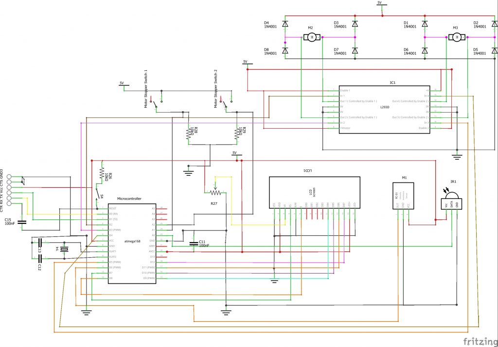
The circuit diagram uses an Atmega168 microcontroller. The microcontroller is designed with a 16MHz crystal for its synchronous clocking speed. As shown in the circuit diagram. This is connected to pin 9 and pin 10 of the IC. This is marked XTAL1 and XTAL2. To aid with this and to suppress noise generated in the chip, we used a 22pF capacitor connected to the same pin, but to be used as a filter, they were connected with respect to the ground.
To burn programs into the IC, we used the 6 male header pins for the connection of our FTDI cable. The FTDI programmer has 6 pins for programming: the CTR or chip reset, the receive pin, which is connected to the transmit pin of the microcontroller, the transmit pin Tx, which is connected to the receiver of the microcontroller, the Vcc power pin that is hooked to +5V and the Chip select that is grounded.
In order to work with the microcontroller and rework with it, there was a need to add a manual reset button. And this is connected to the Active LOW pin (pin 1) of the microcontroller through a 10KΩ precision resistor. This is also called the pull-up resistor that keeps pin 1 of the MCU to see a 5V supply until the reset button is pushed.
The microcontroller needs 100nF capacitors to be connected across its analog Vcc with respect to the ground. And the other connected from the reset pin to the FTDI pin.
The LCD connection is done using the 4-bit method of data connection. No I2C modules or connections were needed since the output digital pins of the microcontroller were enough to communicate with the LCD module. The LCD is powered directly at pins 1, 2, 15, and 16 respectively without using a pull-up resistor for the LED+ backlight pin. The wiper of a 10KΩ pot is connected to the Vo pin of the LCD to adjust the screen contrast. The Register Select (RS) is connected to pin 7 and the Enable of the LCD is connected to pin 8. The 4 data pins are connected at pins 9 through 12 of the microcontroller.
The obstacle avoidance sensor is powered by the 5V power supply while its output pins is connected to digital pin 6 of the microcontroller. This works on HIGH and LOW voltage reverences. Such that the microcontroller uses the HIGH voltage it outputs when it detects an obstacle in its line of sight to set a condition that would allow the gate not to close when it is open and a car is parked between the gates.
The IR receiver is connected to the analog pin 0 which reads the output pin of the IR receiver for HEX code signals. If there is no response from the microcontroller when the user press remote control to the face of the receiver, this is probably because the output pin of the receiver has disconnected from the A0 pin of the MCU.
The stopper switches, which were used to detect when the gate has closed or open worked on analog voltage values such that when they are powered from a 5V reference, and the action of the moving gate tray lodges or dislodge them from this supply; the microcontroller notices these changes and know when the gate is open or not.
The motor driver controls the two DC motors that control the movement of the gate trays. According to the circuit diagram; we connected the inputs of the motor driver to the microcontroller, which in turn outputs a control mechanism depending on which side of the inputs we feed in HIGH and LOW voltages (which is equivalent to 5V and 0V reference). We use the diodes there to prevent reverse feedback mechanisms in terms of voltage back to the MCU or damage to the motor driver chip as a result of electromagnetic energy collapsing when the motor is being cut off from power.
Programming the Microcontroller
Theprogramming of the microcontroller was done using the Arduino IDE. We were able to use the FTDI cable to burn programs into the chip by using the inbuilt complier provided by the Arduino IDE. Below is the code for the project design.
/* THE FOLLOWING PROGRAM CONTROLS THE OPENING AND CLOSING OF
 *  A GATING SYSTEM SUING AN INFRARED TRANSMITTER CONTROL>
 *  ALSO KNOWN AS REMOTE CONTROLLED GATE
 *  Courtesy of Smartech Labs.
 *
 *///include lcd lib
 #include <LiquidCrystal.h>
//include IR lib
#include <IRremote.h>
//declare the instance Lcd and state where the data pins
LiquidCrystal lcd(8, 7, 9, 10, 11, 12);

//declare and state where you connected the IR input pin
int RECV_PIN = A0;

long gateWaitTime = 30;
long timeCount;
long previousMillis = 0;

boolean obstacleRemove = false;

//declare an instance to receive the IR signal
IRrecv irrecv(RECV_PIN);
//decode the IR signals
decode_results results;

//declare the limit switches
int swtch1, swtch2, swtch3, swtch4;

//declare the motordiver inputs
#define motor1Backward 2
#define motor1Forward 3
#define motor2Backward 4
#define motor2Forward 5


//declare and define the pin for IR proximity sensor pin
int proxSensorPin;

void setup()
{
  //begin serial monitor to comm with MCU and PC
  Serial.begin(9600);
  //begin the lcd screen and state what type of lcd used
  lcd.begin(16, 20);
  // In case the interrupt driver crashes on setup, give a clue
  // to the user what's going on.
  Serial.println("Enabling IRin");
  // Start the receiver
  irrecv.enableIRIn();
  Serial.println("Enabled IRin");

  //state the I/O pins
  pinMode(swtch1, INPUT);
  pinMode(swtch2, INPUT);
  pinMode(swtch3, INPUT);
  pinMode(swtch4, INPUT);

  pinMode(motor1Forward, OUTPUT);
  pinMode(motor1Backward, OUTPUT);
  pinMode(motor2Forward, OUTPUT);
  pinMode(motor2Forward, OUTPUT);

  //Print a welcome note
  lcd.setCursor(0, 0);
  lcd.print("WELCOME SMARTECH");
   lcd.setCursor(0, 1);
  lcd.print("     LABS               ");
  delay(2000);
  lcd.setCursor(0, 0);
  lcd.print("REMOTE CONTROLED");
   lcd.setCursor(0, 1);
  lcd.print("  GATE SYSTEM      ");
    delay(2000);
    lcd.setCursor(0, 0);
  lcd.print("  GATE SYSTEM      ");
         lcd.setCursor(0, 1);
  lcd.print("   PROJECT     ");
      delay(2000);
     lcd.setCursor(0, 0);
  lcd.print("  GATE SYSTEM      ");
         lcd.setCursor(0, 1);
  lcd.print("   PROJECT     ");
       lcd.setCursor(0, 0);
  lcd.print("  PLS PRESS A        ");
         lcd.setCursor(0, 1);
  lcd.print(" REMOTE COMMAND     ");
}


void loop() {
  if (irrecv.decode(&results)) {
    Serial.println(results.value, HEX);
    // Receive the next value
    irrecv.resume();
  }

  proxSensorPin = digitalRead(6);
  swtch1 = analogRead(A1);
  swtch2 = analogRead(A2);
  swtch3 = analogRead(A3);
  swtch4 = analogRead(A4);

Serial.println(proxSensorPin);
Serial.print(swtch1);
Serial.print(" ");
Serial.print(swtch2);
Serial.print(" ");
Serial.print(swtch3);
Serial.print(" ");
Serial.println(swtch4);

 if((results.value == 0xFFA25D) && (proxSensorPin == HIGH)) {
  if((swtch2 >= 900) && (swtch3 >= 900)){
  lcd.clear();
      lcd.setCursor(0, 0);
  lcd.print("  GATE OPENING      ");
  lcd.setCursor(0, 1);
   for(int i = 0; i < 10; i++){
    lcd.print(".");
    delay(100);
    digitalWrite(motor1Backward, HIGH);
  digitalWrite(motor2Backward, HIGH);
  digitalWrite(motor1Forward, LOW);
  digitalWrite(motor2Forward, LOW);
  }
  }
       lcd.clear();
 lcd.setCursor(0, 1);
 lcd.print("  GATE OPEN          ");

}


if((results.value == 0xFFE21D) && (proxSensorPin == HIGH)){
  if((swtch2 <= 90) && (swtch3 <= 90)){
  lcd.clear();
         lcd.setCursor(0, 0);
  lcd.print("  GATE CLOSING       ");
  lcd.setCursor(0, 1);
  for(int i = 0; i < 10; i++){
    lcd.print(".");
    delay(90);
    digitalWrite(motor1Backward, LOW);
  digitalWrite(motor2Backward, LOW);
  digitalWrite(motor1Forward, HIGH);
  digitalWrite(motor2Forward, HIGH);
  }
  }
      lcd.clear();
 lcd.setCursor(0, 1);
 lcd.print("  GATE CLOSE         ");

}


if(results.value == 0xFFE21D) {
  if(obstacleRemove == false){
   if((swtch2 <= 90) && (swtch3 <= 90)&& (proxSensorPin == LOW)){
    lcd.clear();
    lcd.setCursor(0, 0);
 lcd.print("OBSTACLE AT GATE  ");
 lcd.setCursor(0, 1);
 lcd.print(" PLEASE REMOVE     ");


   }
}
}

if(results.value == 0xFFA25D) {
   if((swtch2 >= 900) && (swtch3 >= 900)&& (proxSensorPin == LOW)){
    lcd.clear();
      lcd.setCursor(0, 0);
  lcd.print("  GATE OPENING      ");
  lcd.setCursor(0, 1);
   for(int i = 0; i < 10; i++){
    lcd.print(".");
    delay(100);
     digitalWrite(motor1Backward, HIGH);
  digitalWrite(motor2Backward, HIGH);
  digitalWrite(motor1Forward, LOW);
  digitalWrite(motor2Forward, LOW);
  }
  }
  lcd.clear();
 lcd.setCursor(0, 1);
 lcd.print("  GATE OPEN          ");
}

 else if(results.value == 0xFFE21D){
   if((swtch2 <= 90) && (swtch3 <= 90)&& (proxSensorPin == HIGH)){
  obstacleRemove = true;
  if(obstacleRemove == true){
  lcd.clear();
         lcd.setCursor(0, 0);
  lcd.print("  GATE CLOSING       ");
  lcd.setCursor(0, 1);
  for(int i = 0; i < 10; i++){
    lcd.print(".");
    delay(90);
    digitalWrite(motor1Backward, LOW);
  digitalWrite(motor2Backward, LOW);
  digitalWrite(motor1Forward, HIGH);
  digitalWrite(motor2Forward, HIGH);
  }
  lcd.clear();
 lcd.setCursor(0, 1);
 lcd.print("  GATE CLOSE          ");
}
   }
   obstacleRemove = false;
 }


if(timeCount - previousMillis == gateWaitTime) {
if((swtch2 <= 90) && (swtch3 <= 90)&& (proxSensorPin == HIGH) ){
     lcd.setCursor(0, 0);
  lcd.print("  GATE CLOSING       ");
  lcd.setCursor(0, 1);
  for(int i = 0; i < 10; i++){
    lcd.print(".");
    delay(100);
    digitalWrite(motor1Backward, LOW);
  digitalWrite(motor2Backward, LOW);
  digitalWrite(motor1Forward, HIGH);
  digitalWrite(motor2Forward, HIGH);
  }
  lcd.clear();
 lcd.setCursor(0, 1);
 lcd.print("  GATE CLOSE          ");
}
}
timeCount= previousMillis;
timeCount = millis()/1000;
Serial.println(timeCount);
    delay(500);
}
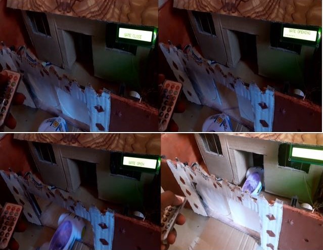
Uploading the above syntax into the Arduino IDE, we would find the system working as expected. It should be noted that the HEX codes used for controlling gate movement differs in each remote controls (IR transmitter modules). To learn how to decode your own HEX code, check out our tutorials on that.
The LCD would display a welcome message and show the title of the project, smart infrared remote control gate system.
To view the tutorial video, just click on the youtube clip below to watch
Conclusion
Building a Remote Gate Opener DIY system is one of those projects that looks technical but is actually fun and manageable. Once you install it, you’ll enjoy the comfort of opening your gate from your car, your porch, or even your bedroom.
Not only does it add convenience, but it boosts security, adds value to your home, and gives you a sense of achievement — because you built it.
So gather your tools, grab your components, and start creating your own smart automated gate system today.

