In this project tutorial, we will design and construct a solar-powered smart irrigation system with SMS notification. The system design is an automatic smart project that has the capacity to detect the relative humidity, optimum temperature, and soil moisture level of a garden or farm using special soil moisture sensors and relay this data to an authorized user phone via short message service (SMS). The project design also uses the level of water in the soil to determine when to turn on a DC power pump to pump water into the farm for irrigation purposes automatically. This means it totally eliminates the human labor part in running the irrigation in both arid and well-watered places.
Material/Components Needed
In assembling the components and parts needed for the design of this project; we took into consideration the underlined objectives: materials that are not too expensive, readily available, and we could use them to obtain our desired aims.
- 12V DC pump………………………………………………………………………….1pcs
- Soil Moisture sensor……………………………………………………………2pcs (or 1)
- Single Channel Relay Module………………………………………………………1pcs
- Temperature and humidity sensor module……………………………………..1pcs
- Microcontroller Unit (Standalone or Arduino made)………………………….1pcs
- FTDI ISP programming cable………………………………………………………..1pcs
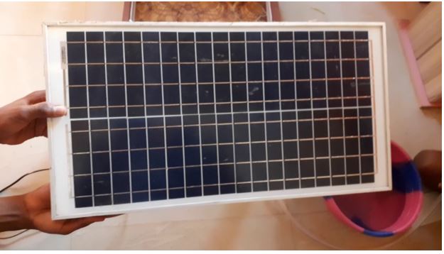
- 30W PV panel……………………………………………………………………………..1pcs
- 30A solar charge controller……………………………………………………………1pcs
- 12V 7Ah backup battery…………………………………………………………………1pcs
- SIM800L GSM module………………………………………………………………….1pcs
- Prepaid SIM card and some airtime.
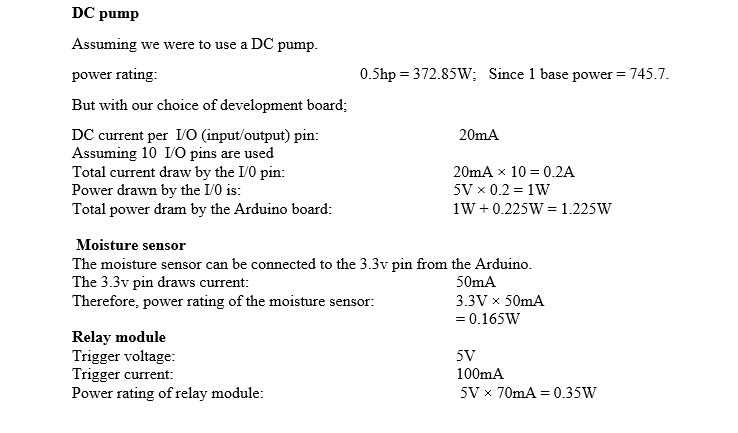
Theoretical Calculations
Solar Based Smart Irrigation System with SMS Notification: Design the Framework/Woodwork
The system design had its backbone on the base which shows off the surface where to lay soil for planting of crops. To design the real model of such garden, we used a compressed wood frame. The wood was first analyzed for structural defects and when ascertained to be minimal; we set out for the dimensioning.
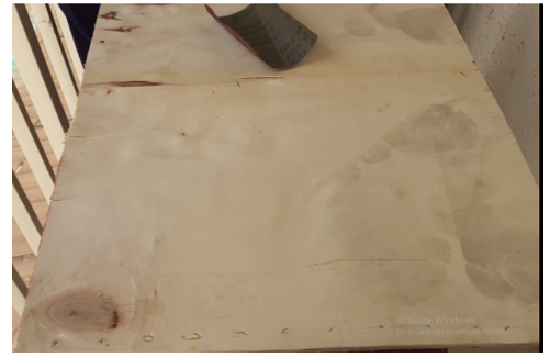
The wood for the fence of the building was made with dimension of length of about 65cm, the breath is about 3cm and the height is 8cm. We used a different wood for this.
The shape of the model garden was rectangular, with no opening. Once we have gotten the fencing structure ready we proceeded to nailing them together. Before this, we polished the base surface and then applied a wood glue to the surface. After a small while, use used a top wrapper to cover it. This was a Glossy Laminate formaica sheets. And this gave is the impression we were looking for. This better choice since we didn’t want the compressed base wood to be getting wet and decaying very quickly as we are pumping water through sprinkling into the garden fam model.

After nailing the barricades we have ourselves a look we were looking for as shown below.
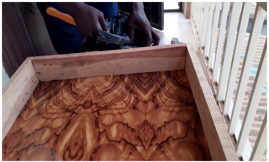
Next we used wood filler powder to fill some of the minor openings that were between each joining of the woods.
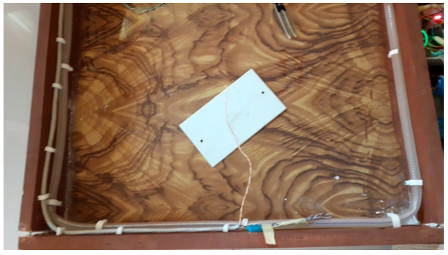
We laid the hose around the wall of the fence to form our sprinkling pattern. The hose was further punched at different locations to allow sprinkles of water when the DC pump is turned on.
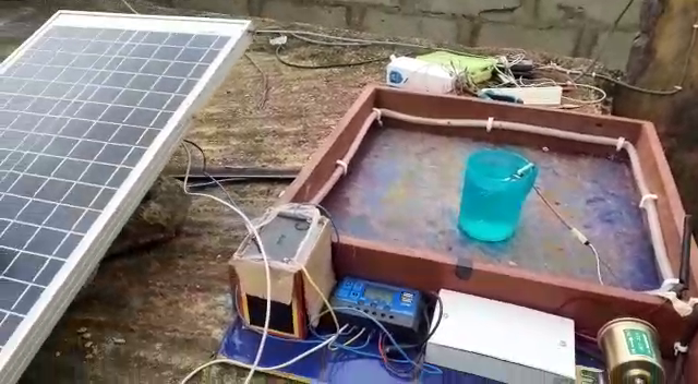
The soil moisture sensor and temperature and humidity sensor module (DHT11) are positioned at the best place to take readings. After this, we wire the inside for our soil moisture sensors. We also included the digital and humidity sensor. Then we proceeded to making an external base where we can place out rechargeable battery, solar charge controller and the microcontroller development unit.
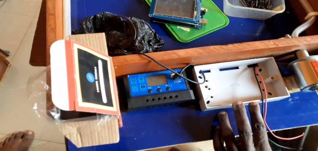
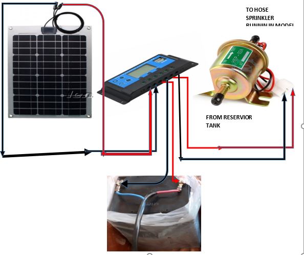
The connection in the picture diagram above is almost what we connected for the solar grid in the project design. We however connected the standalone microcontroller development board to the 5V USB terminal above the charge controller.
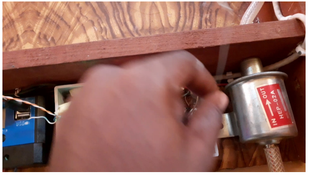
First, the battery was connected to the charge controller. After which, we connect the PV array lastly followed by the load which is the DC pump. But until in the actual design, one of the power rails of the DC pump is connected to the single channel relay module. Which would act as a switch for turning on and turning off of the DC pump by the MCU (This is shown in the schematic diagram below).
The Microcontroller unit (MCU) was enclosed in the 3×6 adaptable box shown below. From this box we connected every other part to the design.
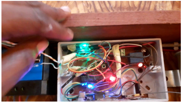
The GSM module. The soil moisture sensors and the dht11 sensor were all encased in a plastic 3×6 patress box. Which is then screwed unto the base of the partition of the wooded base reserved for the power and controls for the garden model. The battery also alongside the solar charge controller is kept on this partition to avoid water from getting into the power leads. We powered the MCU from one of the two 5V output reserves using a USB female socket. While taking a 12V from the output of the solar charge controller then passing it through a DC-Dc buck converter before stepping it down to 3.3V which we used to power the GSM module.
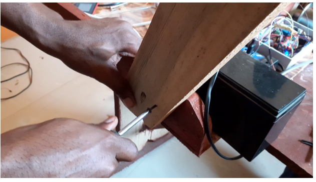
Constructing the Stand for the PV array:
Solar-powered Smart Irrigation System with SMS: Circuit Diagram
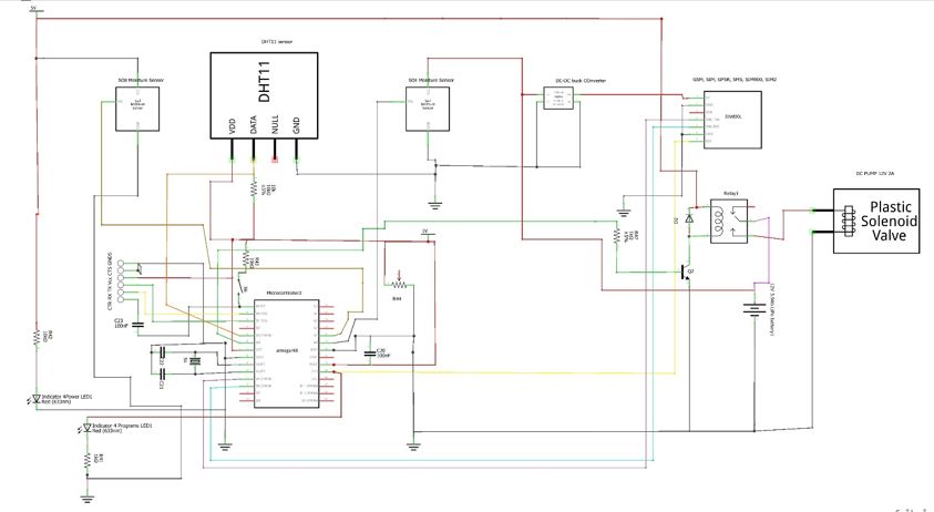
The SIM800L power supply also came from the 12V load output on the charge controller which could only supply the GSM module the rated current (about 2A) it needs to kick-start itself. But we used a DC-DC buck converter for this to ensure that, we stepped it down to 3.4V. The following below is the syntax that was compiled in the Arduino IDE unto the MCU board.
#include <SerialGSM.h>
#include <SoftwareSerial.h>
SerialGSM cell(10,11);
// Include DHT library and Adafruit Sensor Library
#include "DHT.h"
#include <Adafruit_Sensor.h>
// Pin DHT is connected to
#define DHTPIN 7
// Uncomment whatever type of sensor you're using
#define DHTTYPE DHT11 // DHT 11
//#define DHTTYPE DHT22 // DHT 22 (AM2302)
//#define DHTTYPE DHT21 // DHT 21 (AM2301)
// Initialize DHT sensor for normal 16mhz Arduino
DHT dht(DHTPIN, DHTTYPE);
// Create global varibales to store temperature and humidity
float t; // temperature in celcius
float f; // temperature in fahrenheit
float h; // humidity
float soil; //soil moisture
String SMS;
String Invalid;
String stat;
String Pump_State;
const int pump = 13;
boolean sendonce=true;
void setup(){
// sensors.begin();
dht.begin();
Serial.begin(9600);
cell.begin(9600);
cell.Verbose(true);
//cell.Boot();
//cell.DeleteAllSMS();
cell.FwdSMS2Serial();
delay(2000);
Serial.println("AM READY FOR YOU\n");
pinMode(pump, OUTPUT);
delay(2000);
}
boolean readData() {
//Read humidity
h = dht.readHumidity();
// Read temperature as Celsius
t = dht.readTemperature();
// Read temperature as Fahrenheit
f = dht.readTemperature(true);
// Compute temperature values in Celcius
t = dht.computeHeatIndex(t,h,false);
// Uncomment to compute temperature values in Fahrenheit
//f = dht.computeHeatIndex(f,h,false);
// Check if any reads failed and exit early (to try again).
if (isnan(h) || isnan(t) || isnan(f)) {
Serial.println("Failed to read from DHT sensor!");
return false;
}
Serial.print("Humidity: ");
Serial.print(h);
Serial.print(" %\t");
Serial.print("Temperature: ");
Serial.print(t);
Serial.print(" *C ");
//Uncomment to print temperature in Farenheit
//Serial.print(f);
//Serial.print(" *F\t");
return true;
}
void loop(){
// Convert the analog reading (which goes from 0 - 1023) to a range (0 - 100):
soil = analogRead(A2)*100.00/1023.00;
soil = constrain(soil, 2.00, 100.00);
soil = map(soil, 100.00, 2.00, 2.00, 100.00);
if (soil <= 65.00)
{
digitalWrite(pump, HIGH);
Pump_State = "ON";
}
if ( soil >= 70.00)
{ digitalWrite(pump, LOW);
Pump_State = "OFF";
}
if (cell.ReceiveSMS()){
Serial.println("NEW SMS ARRIVED");
delay(100);
stat = cell.Message();
if(readData()){
cell.Rcpt(cell.Sender());
delay(500);
Serial.print("Sender: ");
Serial.println(cell.Sender());
delay(2000);
Serial.print("Messsage: ");
Serial.println(cell.Message());
delay(2000);
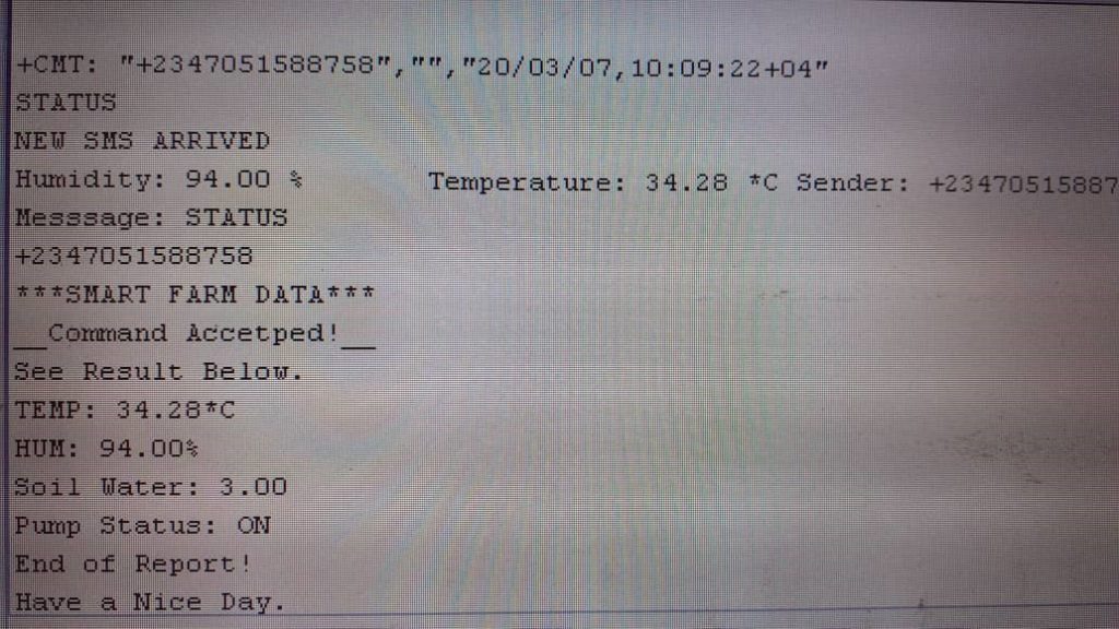
SMS = ("***SMART FARM DATA***\n__Command Accetped!__\nSee Result Below.\nTEMP: " + String(t) + "*C \nHUM: " + String(h) + "%\nSoil Water: " + String(soil) + "\nPump Status: " + Pump_State + "\nEnd of Report!\nHave a Nice Day.");
Invalid = "SMS received but I don't recognize your command.\nKindly Contact Mr. Damilare for list of acceptable commands.\nThanks.";
int m = SMS.length();
char Send[m + 1];
strcpy(Send, SMS.c_str());
int i = SMS.length();
char invalid[i + 1];
strcpy(invalid, Invalid.c_str());
if(stat == "STATUS"){
cell.Message(Send);
}
else{cell.Message(invalid);}
cell.SendSMS();
delay(2000);
Serial.println("message sent!\n");
cell.DeleteAllSMS();
}
}
}
Source Code Explanation
The code began with us importing two libraries that were very important; the GSM library and the software serial library. Next we defined where we connected out receiver and transmitter pin of our SIM800L to the MCU using variable name cell. We culled two more libraries for the DHT11 sensor and defined where we connected the pin. We defined and told the MCU which type of DHT sensor we were using. Other variable names were define to denote temperature and humidity. We defined a String type of variable to hold the SMS to be sent out size. We defined our pump state and its single channel relay pin.
In our setup() function, we began the Dht11 sensor, and jump started the SIM800L. Once it was ready, we asked it to print out a message (AM READY FOR YOU) on the serial monitor.
WE used another function, this time a Boolean function readData that wouild be reading and logging the DHT11 sensor. And once the sensor is reading that means it is true and it can always output the data to our serial communication which in turn communicate with the GSM module.
In the loop() function, the String SMS is sent out when the incoming text is ‘STATUS’. When the incoming SMS matches the word; STATUS, the MCU prompts the SIM800L to send out the message.
The if conditions that are coded after the constrained and mapped values pf the soil moisture sensor allows for us to set the rate at which we can pump the water into the farm. As stated here, the pumps kicks in when the sensor measure a wetness that is below 65.00 and pumps until the wetness goes above 70.00.
Results and Analysis
The project, Solar-powered Smart Irrigation System with SMS worked very well as expected when tested after successful compilation of the code into the MCU. Once the SMS that contains the text ‘STATUS’ is sent to the SIM card inserted into the SIM800L module and it confirms reception; it quickly replies with the status of the farm that contains:
The syntax is supposed to take care of when the incoming SMS doesn’t match the String ‘STATUS’ and reply the sender by telling it that it doesn’t recognize the command. The design can also be sent a command in SMS format of “TURN PUMP ON” and it will turn on the DC pump and would turn it off by itself on the irrigated water level on the garden is enough to avoid flooding of the whole garden model.
Conclusion
Now we have shown you how we achieved this project, Solar-powered Smart Irrigation System with SMS Notification. Kindly let us know if you were able to build such similar project or a better version. We will be very glad to help you the best we we can. Let us know if you have any further questions in the comment section. You can also drop a suggestion too! To join the conversation, join our Telegram community, Telegram, Facebook page, Instagram and Twitter.

