Blog

  • Power Management System for Home- A Smart Fan Project

    Power Management System for Home- A Smart Fan Project

    This Power Management System for Home-A Smart Fan Project transforms a standing air conditioning fan into a smart automated version that detects human presence using a passive infrared (PIR) sensor and then sets two distinct time modes using a real-time clock (RTC). The “Auto Sense Mode” and “Remote Active Mode” in particular. The user could utilize the remote control to access the desired speed selection during the “working hour,” also referred to as the “Remote Active Mode.” The fan operates on its own while it is in Auto Sensing mode. The fan knows when to switch to auto mode thanks to the RTC sensor. It may then use the PIR sensor to identify human movements and determine whether someone is in need. During the Auto Sensing mode, the fan controls itself automatically. With the RTC sensor, the fan can tell when it is time for auto mode. And then, using the PIR sensor, it could detect human motion and know when there is somebody around needing cool air ventilation. If the fan senses motion, it would turn itself on and run at a constant speed, which is the speed of two. But if, after some time, it couldn’t detect any motion, it would turn itself off.

    Materials/Components Needed

    1. Pedestal Fan

    Pedestal Fan
    Pedestal Fan

    A standing electric fan designed to circulate air efficiently in a room. It typically has adjustable height, oscillation, and speed settings.


    2. Atmega328P IC
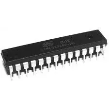
    Atmega328P IC
    Atmega328P IC

    A widely used 8-bit microcontroller from the AVR family, commonly found in Arduino boards. It controls input/output devices, processes data, and runs embedded programs.


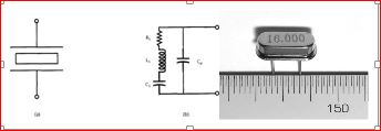
    3. 16MHz Crystal Oscillator
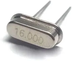
    16MHz Crystal Oscillator
    16MHz Crystal Oscillator

    A timing device that provides a stable 16 MHz clock signal to the microcontroller, ensuring accurate processing speed and synchronization of operations.


    4. 1602 LCD Module
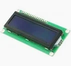
    1602 LCD Module
    1602 LCD Module

    A 16×2 character Liquid Crystal Display used to show alphanumeric information, such as sensor readings, status messages, or system outputs.


    5. 10k Potentiometer
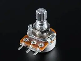
    10k Potentiometer
    10k Potentiometer

    A variable resistor used to adjust voltage levels. Commonly used to control the contrast of LCD displays or tune analog signals.

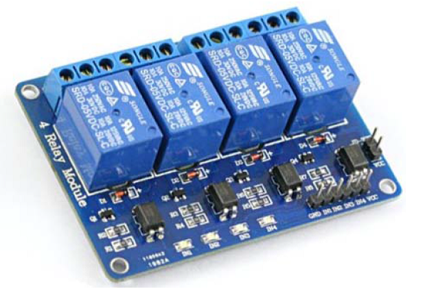
    6. 3-Channel Relay Module
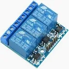
    3-Channel Relay Module
    3-Channel Relay Module

    An electronic module that allows the microcontroller to switch high-voltage devices (like fans, lamps, or motors) on and off safely through low-voltage digital signals.

    Buy Full complete kit for this project on our online store or contact us via WhatsApp

    Circuit/Schematic Diagram

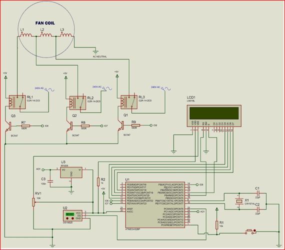
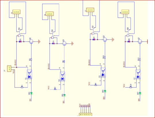
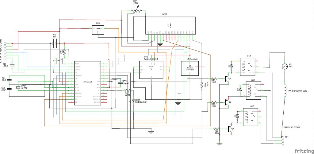
    The project design started with us designing the circuit diagram using the Fritzing circuit IDE. As shown in the picture below.
    Power Management System for Home- A Smart Fan Project
    Circuit Diagram for the project design

    Circuit Diagram Explanation

    Following the circuit diagram, we built the standalone development board around the Atmega328P-U microcontroller. For other projects that used Atmega328P-PU microcontroller, check out: Atmega328P-U projects

    So here, the atmega328P-U microcontroller unit (MCU) is programmed using the FTDI ISP programmer as shown above. We used a DS3231 type of RTC to keep and set our time. We used a PIR sensor to detect the motion also. The connection is set such that the serial clock pin (SCL) and the serial data pin (SDA) of the RTC are connected to the analog pin 5 (A5) and analog pin 4 (A4) of the MCU, respectively. The PIR output is connected to the digital pin 10 of the Atmega328P-U.

    Next that catches our interest is the 16×4 LCD connection. As shown in the circuit diagram, we are using the 4-bit connection mode (4-wire type connection). We wired Register Select (RS) to MCU D3, Enable pin (E) to D4, and the four data pins to digital pins 8 through 5.

    Note: If you are using a power supply that has a DC output above 5V, you have to use a voltage regulator as shown in the circuit diagram to buck it down to 5V since the MCU uses a 5V DC output. But ensure that your 5V meets up to 3A. Otherwise, during relay switching, the LCD screen may scatter and start misbehaving. Also, if you don’t use a 5V DC supply, the whole system will end up getting fried.

    To switch the states of the AC standing fan, we need a 3-channel relay module to change the speed controls automatically.
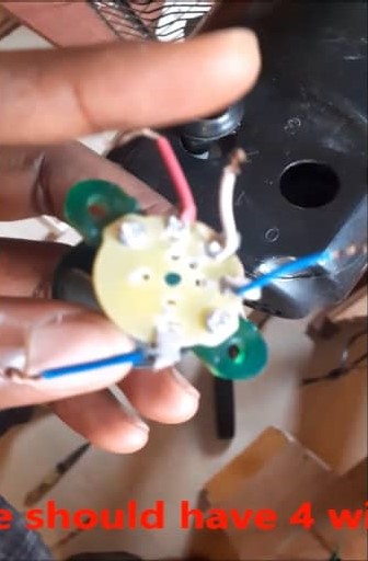
    Power Management System for Home- A Smart Fan Project
    Speed regulator switch

    Here we disconnected the normal speed selector switch found on the standing fan and extended it with more wires. Then the AC live wire is connected to the common of the relays while the respective speed lines are connected to the other three, as shown in the picture above. The neutral line of the AC is connected to the neutral of the fan induction coil.

    Arduino Source Code

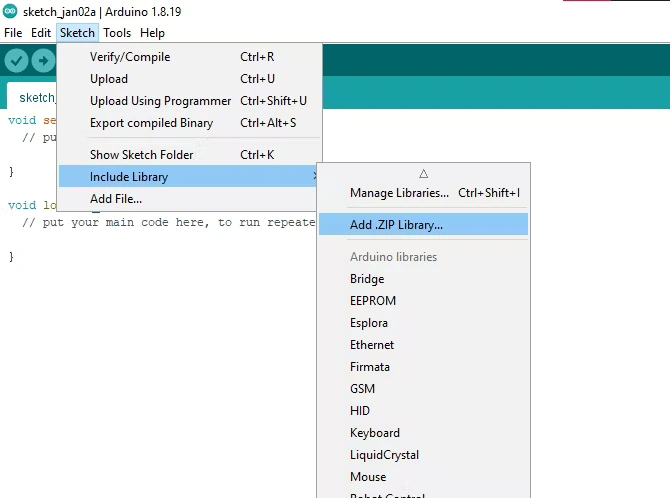
    After the connection has been made, the PIR sensor and the RTC are connected too to the MCU board. The LCD module is connected to its header pin. Next is to program the MCU. Copy the code below into your Arduino IDE.

    #include <Wire.h>
    
    #include <RTClib.h>
    
    #include <EEPROM.h>
    
    #include <IRremote.h>
    
    #include <LiquidCrystal.h>
    LiquidCrystal lcd(3, 4, 8, 7, 6, 5);
    
    RTC_DS3231 rtc;
    
    char daysOfTheWeek[7][12] = {"Sunday", "Monday", "Tuesday", "Wednesday", "Thursday", "Friday", "Saturday"};
    
    #define speed1 A0
    #define speed2 A1
    #define speed3 A2
    int RECV_PIN = 2;
    const int PIR = 10;
    unsigned long count = 0;
    int state = LOW;
    int currentState = 0;
    int previousState = 0;
    int sensor_count = 0;
    int timer = 0;
    int ts = 50;
    int tc = ts;
    int sc = 10;
    int fail = 0;
    int ms = 50;
    unsigned long pm = 0;
    const long interval = ms;
    boolean logic;
    
    byte val0 = EEPROM.read(0);
    byte val1 = EEPROM.read(1);
    byte val2 = EEPROM.read(2);
    
    int ontime = val1;
    int offtime = val2;
    int menu = 0;
    int pause = 50;
    int rtcDAY, rtcMONTH, rtcYEAR, rtcHOUR, rtcMIN, rtcSEC;
    int minus = 0;
    int plus = 0;
    int fan = 0;
    String remote;
    String stat = ""; 
    String SPEED = "";
    
    IRrecv irrecv(RECV_PIN);
    decode_results results;
    
    void page(){
        DateTime now = rtc.now();
        lcd.setCursor(0, 0);
        lcd.print("RUKE's SMART FAN");
        lcd.setCursor(0, 1);
        lcd.print(SPEED);
        lcd.setCursor(0, 2);
        lcd.print(stat); 
        lcd.setCursor(0, 3);
        lcd.print(now.day(), DEC);
        lcd.print('/');
        lcd.print(now.month(), DEC);
        lcd.print('/');
        lcd.print(now.year(), DEC);
        lcd.print("  ");
        lcd.print(now.hour(), DEC);
        lcd.print(':');
        lcd.print(now.minute(), DEC);
               }
    void fanOff(){
       //turn the fan off
       analogWrite(speed1, 255);
       analogWrite(speed2, 255);
       analogWrite(speed3, 255);
       SPEED = "     FAN OFF      ";
    }
    void spd1(){
       //turn the fan off
       analogWrite(speed1, 0);
       analogWrite(speed2, 255);
       analogWrite(speed3, 255);
       SPEED = "     speed 1      ";
    }
    void spd2(){
       //turn the fan off
       analogWrite(speed1, 255);
       analogWrite(speed2, 0);
       analogWrite(speed3, 255);
       SPEED = "     speed 2      ";
    }
    void spd3(){
       //turn the fan off
       analogWrite(speed1, 255);
       analogWrite(speed2, 255);
       analogWrite(speed3, 0);
       SPEED = "     speed 2      ";
    }
    void SenSe(){
      unsigned long cm = millis();
    unsigned long rr = cm - pm;
    if(rr > interval){
       if(digitalRead(PIR)==HIGH){
        sensor_count = sensor_count + 1;
           }
    timer = timer + 1;
    pm = cm;
     if(timer >= tc){
      if((sensor_count >= sc) && (tc >= ts)){    
        spd2();
        tc = 0;
        fail = 0;
      }
      else{
        fail = fail + 1;
        tc = ts;
        //interval = ms;
      }
      timer = 0;
      sensor_count = 0;
        }
    }
    if(fail > 20){
      fail = 0;
      fanOff();
      }
    }
    
    void setup() {
      // put your setup code here, to run once:
    Serial.begin(9600);
    lcd.begin(16, 4);
    
    pinMode(speed1, OUTPUT);
    pinMode(speed2, OUTPUT);
    pinMode(speed3, OUTPUT);
    pinMode(PIR,INPUT);
    
    if (! rtc.begin()) {
      lcd.setCursor(0, 0);
        lcd.print("Can't find RTC");
        delay(3000);
        while (1);
      }
    
      if (rtc.lostPower()) {
        lcd.setCursor(0, 0);
        lcd.print("RTC lost power!");
        // following line sets the RTC to the date & time this sketch was compiled
        rtc.adjust(DateTime(F(__DATE__), F(__TIME__)));
        
        delay(3000);
      }
    
    // In case the interrupt driver crashes on setup, give a clue
      // to the user what's going on.
      Serial.println("Enabling IRin");
      irrecv.enableIRIn(); // Start the receiver
      Serial.println("Enabled IRin");
    
      fanOff();
    }
    
    void loop() {
      // put your main code here, to run repeatedly:
      DateTime now = rtc.now();
      rtcHOUR = now.hour(), DEC;
      if (irrecv.decode(&results)){
      remote = String(results.value, HEX);
        if(remote == "511dbb"){
       menu = 1;
      }
        Serial.println(menu);
        Serial.println(fan);
        Serial.println(remote);
        irrecv.resume(); // Receive the next value
      }
     
      if((rtcHOUR >= ontime) && (rtcHOUR <offtime))//Comparing the current time with the Alarm time
        { 
          stat = "    Auto Mode      ";
          SenSe();
        
        }
        else{
          if(remote == "c101e57b"){
            fanOff();
        }
        if(remote == "9716be3f"){
            spd1();
        }
        if(remote == "3d9ae3f7"){
            spd2();
        }
        if(remote == "6182021b"){
            spd3();
        }
         stat = "  Remote Active     ";
        
         
        }
    if(menu < 1){
    page();
    }
        menu = constrain(menu, 0, 5);
        switch(menu){
      case 1:
        lcd.setCursor(0, 0);
        lcd.print("**Control MENU**  ");
        lcd.setCursor(0, 1);
        lcd.print(">1. FAN ON Time  ");
        lcd.setCursor(0, 2);  
        lcd.print(" 2. FAN OFF Time  ");
        lcd.setCursor(0, 3);  
        lcd.print(" 3. EXIT MENU      ");
          if(remote == "a3c8eddb"){
          menu++;
           if(menu > 3){
          menu = 1; }
              }
          if(remote == "f076c13b"){
          menu--;
           if(menu < 1){
          menu = 3; }
               }
          if(remote == "e5cfbd7f" && menu == 1){
          menu = 4;      
          }   
          break;
      
     case 2:
        lcd.setCursor(0, 0);
        lcd.print("**Control MENU**  ");
        lcd.setCursor(0, 1);
        lcd.print(" 1. FAN ON Time     ");
        lcd.setCursor(0, 2);  
        lcd.print(">2. FAN OFF Time   ");
        lcd.setCursor(0, 3);  
        lcd.print(" 3. EXIT MENU    ");
          if(remote == "a3c8eddb"){
          menu++;
           if(menu > 3){
          menu = 1;}
                }
          if(remote == "f076c13b"){
          menu--;
           if(menu < 1){
          menu = 3; }
              }
          if(remote == "e5cfbd7f" && menu == 2){
          menu = 5;      
          }   
        break;
    
       case 3:
        lcd.setCursor(0, 0);
        lcd.print("**Control MENU**  ");
        lcd.setCursor(0, 1);
        lcd.print(" 1. FAN ON Time");
        lcd.setCursor(0, 2);  
        lcd.print(" 2. FAN OFF Time");
        lcd.setCursor(0, 3);  
        lcd.print(">3. EXIT MENU    ");
          if(remote == "a3c8eddb"){
          menu++;
           if(menu > 3){
          menu = 1;}
            }
          if(remote == "f076c13b"){
          menu--;
           if(menu < 1){
          menu = 3;
          }
                }
        if(remote == "e5cfbd7f" && menu == 3){
          menu = 0; }
        break; 
    
      case 5:
        lcd.clear();
        offtime = constrain(offtime, 0, 23);
        lcd.setCursor(0, 0);
        lcd.print(" SET AC OFF Time:   ");
        lcd.setCursor(0, 2);  
        lcd.print("New Time = ");
        lcd.print(offtime);
        lcd.print(":00      ");
        if(remote == "a3c8eddb"){
          offtime++;
           if(offtime > 23){
          offtime = 0;
          }
              }
        if(remote == "f076c13b"){
        offtime--;
        if(offtime < 0){
          offtime = 23;
          }
           }
        if(remote == "e5cfbd7f" && menu == 5){
          EEPROM.update(2, offtime);
          menu = 2;
        }
        break;
    
      case 4:
        lcd.clear();
        ontime = constrain(ontime, 0, 23);
        lcd.setCursor(0, 0);
        lcd.print(" Set FAN ON Time   ");
        lcd.setCursor(0, 2);  
        lcd.print("New Time = ");
        lcd.print(ontime);
        lcd.print(":00      ");
        if(remote == "a3c8eddb"){
          ontime++;
           if(ontime > 23){
          ontime = 0;}
              }
        if(remote == "f076c13b"){
          ontime--;
           if(ontime < 0){
          ontime = 23;}
              }
        if(remote == "e5cfbd7f" && menu == 4){
          EEPROM.update(1, ontime);
          menu = 1;
        }
        break;
          }
          remote = "";
          delay(50);
        }
    

    Arduino Sketch Explanation

    As shown from above, four libraries are needed in this Power Management System for Home- A Smart Fan Project sketch: the RTC library, the lcd library, the IR receiver library and the EEPROM lib. Although some of these libraries are already in the Arduino IDE.

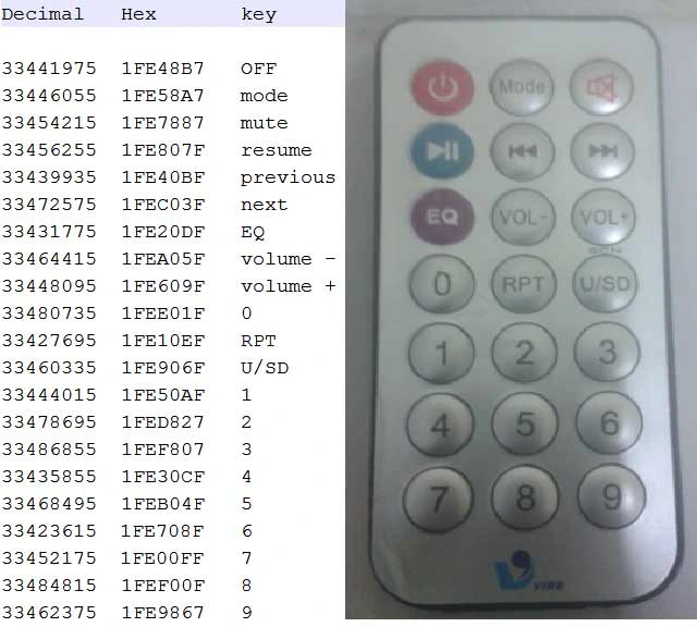
    You can change the time for the Remote active mode and the Auto mode in the design after successful uploading the code and using your remote controller to adjust it. To design which of the button does your bidding, you have to run the IR receiver test and map out the received IR HEX values. Then you would in turn use these HEX codes, to assign a specific command in the IF statement you coded.

    We used Analog pins for your relay module inputs which in turn controls the AC fan speeds and we defined in the code lines above. The page function greeting message could be altered to any of the programmer’s choice. functions like fanOff(), spd1(), spd2() and spd3() were used to control the state of each relay on the relay module and which in turn regulate the fan speed. As seen in the sketch, function fanOff() turns off all the inputs of the relay module by gving them 8-bit -1 (255) voltage level (which is a HIGH). Since the relay module is active LOW, this would turn off all the inputs.

    function Sense() controls the PIR sensor and its counting mechanism. Virtually, we just increased the delay time to 10 seconds (int sc =10). After 20 seconds in the auto mode, if it doesn’t sense any motion, it automatically turns off.

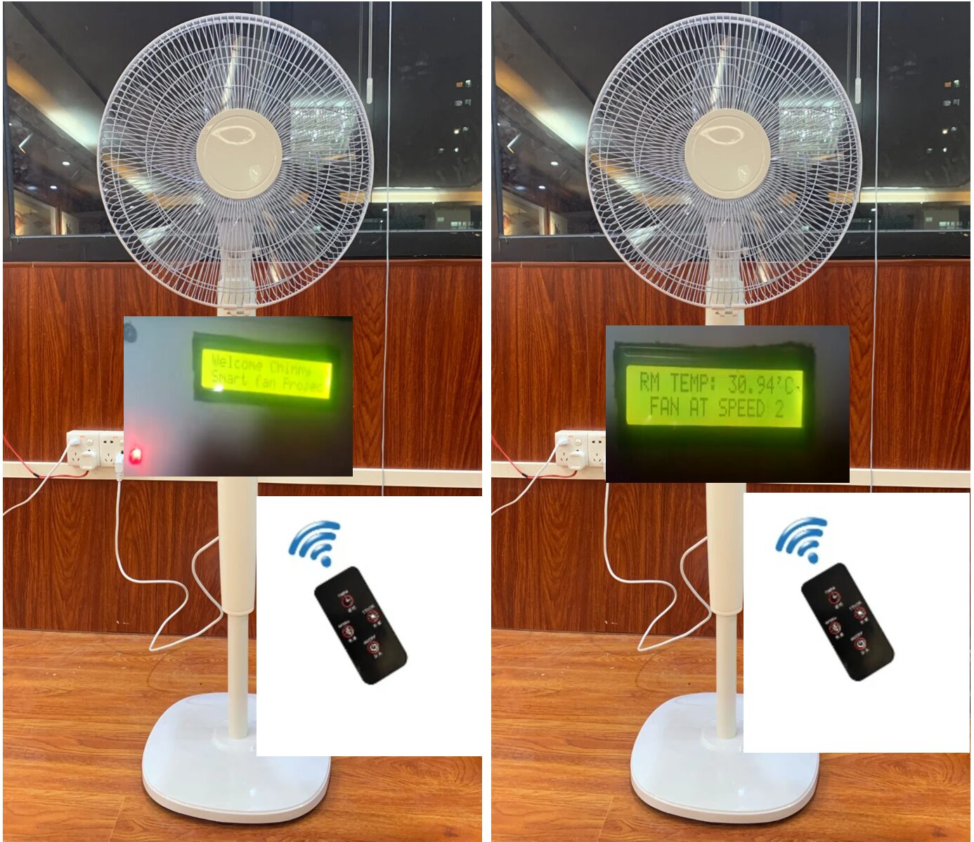
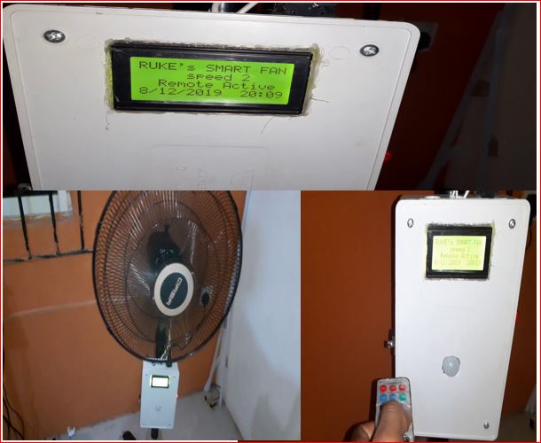
    A visual of the Power Management System for Home-A Smart Fan Project is given below for more explanation.

    Smart Fan Project

    Conclusion

    And that is it for this post. If you have any questions, just leave a comment in the comment section below. You can also see our other posts or check out our online store if you are a tech enthusiast. Let us know how we can assist you. Any time!

    Thank you.
  • How to Build an SMS Based Metal Detector

    How to Build an SMS Based Metal Detector

    How to Build an SMS Based Metal Detector
    How to Build an SMS Based Metal Detector

    Imagine a system that can detect metals on a person and immediately send you an SMS alert to notify you. Such a system can be pivotal in monitoring areas remotely and quickly responding to potential threats. In this tutorial, we’ll walk you through how to build an SMS-based metal detector using Arduino, a GSM module, and other components that will make your metal detection project both effective and scalable.
    This project, how to build an SMS-based metal detector design and construct a metal detector with SMS alert by incorporating a metal detector sensor to detect metallic objects in close proximity. It would instantly send out an SMS to a predefined personnel’s phone number once a metal or electronic device(s) was detected. The design has features like its portable size, and runs on rechargeable batteries. In designing this project, we had to calculate the feasibility of the needed materials’ cost in order to make sure that we were not undertaking an exorbitant project. This SMS-based metal detector project is about metal detector design with SMS notification. Below is a description of the components used for the implementation of the Metal Detector with SMS Alert system design.

    What is an SMS-Based Metal Detector?

    An SMS-based metal detector is a smart security system designed to detect the presence of metal objects on an individual’s body and send an SMS notification to a specified recipient when metal is detected. The core functionality of the system relies on a metal detection sensor, which senses metal objects and triggers an SMS through the GSM module.

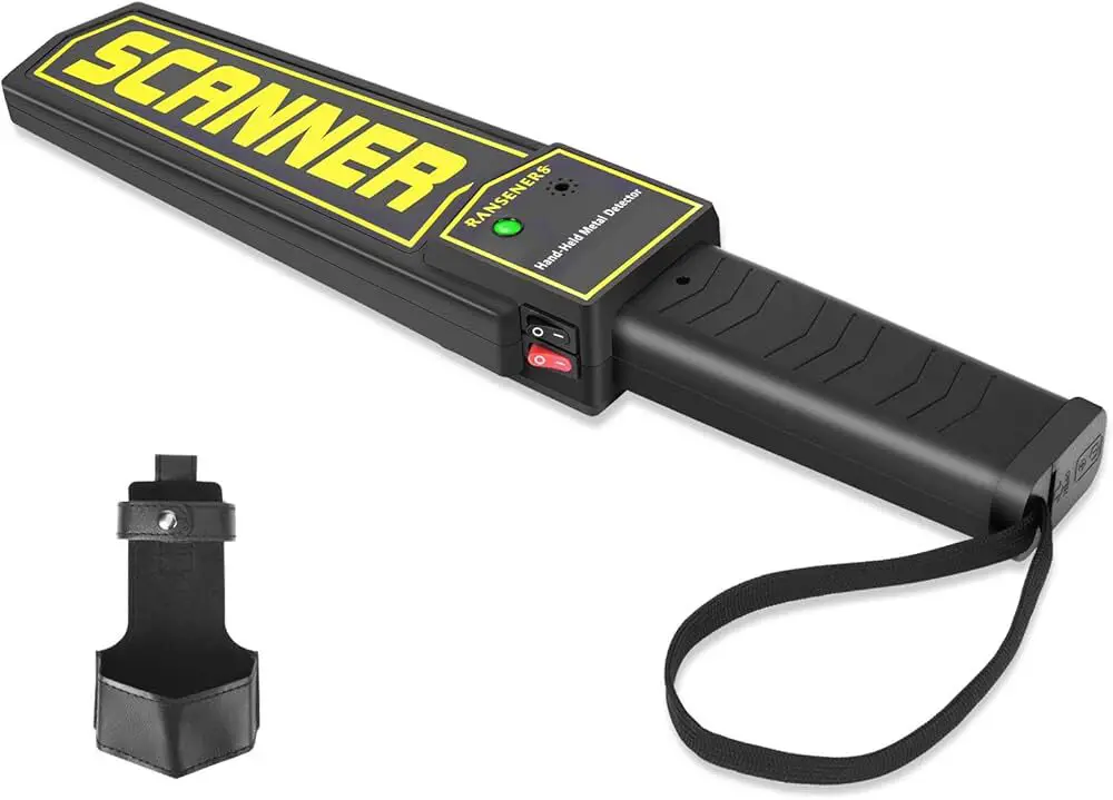
    A traditional handheld metal detector device
    A traditional handheld metal detector device

    This system can be installed at various checkpoints, providing an alert mechanism for security personnel. Whether it’s detecting concealed weapons or other unauthorized metallic items, this tool can significantly enhance security.

    How Does an SMS-Based Metal Detector Work?

    The working principle of this system is simple yet effective. When a metal object comes within the detection range of the sensor, it sends a signal to the Arduino, which is the main controller. The Arduino processes this input and sends a command to the GSM module, which in turn sends an SMS to a pre-configured mobile number, alerting the security personnel.

    This makes it particularly useful for real-time monitoring of restricted areas. Additionally, this system can be customized to operate efficiently in different environments, making it a versatile solution for various security applications.

    MATERIALS/COMPONENTS

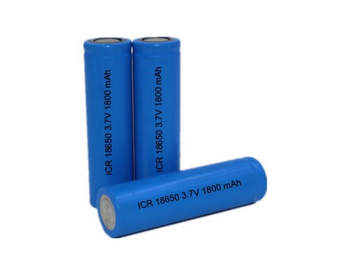
    • 3.7V 1800mAh Li-ion Rechargeable Battery
    • 3.7V 1800mAh Casing
    • 3.7 Lipo 1A Battery Charging Board Charger Module Mini USB Interface
    • LM323T Voltage Regulator
    • The 1k resistor
    • 330-ohm resistor
    • LED
    • 1N4148 diode
    • Perforated board (stripped line type)
    • Connecting jumper wire
    • 10nF capacitor
    • GSM Module (SIM900L)
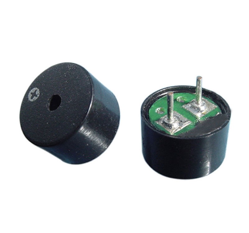
    • 5V Passive Buzzer

    Buy the complete kit for this project on our online store or kindly chat us on WhatsApp

    3.7V 1800mAh Li-ion Rechargeable Battery:

    The Power Unit for the design depended mainly on DC supply from rechargeable batteries, each rated 3.7V 1800mAh. And 3 pieces of 3.7V 1800mAh Li-ion batteries gave us the needed Voltage for GSM module. Also, these were rechargeable batteries so we used Lipo battery charging board.

    how to build an SMS based metal detector project design: The rechargeable battery
    how to build an SMS based metal detector project design: The rechargeable battery

    The 3.7V rechargeable battery can output a current of 1.8A for one hour. It is durable and can be charged very quickly. It is also portable and, as such, was ideal for using as a power source for the project design.

    Read Also How to Make Money as A student with these 10 Free Money-Making Sites

    3.7V 1800mAh Casing:

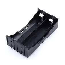
    The above pictured batteries needed a casing, so we used one 3.6V-3.7V Battery Charging Discharging Control Holder Case.  Li-ion battery with 1S3P PCM.

    LiPo Battery casing
    3.6V-3.7V Battery Charging Discharging Control Holder Case  Li-ion w/1S3P PCM

    This is a plastic DIY Lithium battery box battery holder with pin suitable for 2×18650 (3.7V-7.4V) Lipo battery. The casing is of high quality and can withstand temperatures of about 95°C. It maintains firm hold with the batteries inside it and offers safety from short circuiting and wire burn out. A total of 3 battery were connected in series to give us a 12V approximately 5A output for the GSM module.

    Read Also The Salem Witch Trials (1692-1693)

    3.7 Lipo 1A Battery Charging Board Charger Module Mini USB Interface:

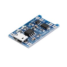
    How to Build an SMS Based Metal Detector: The LiPo battery charging board
    3.7 Lipo Charger board

    The Lipo charging board module uses mature charging chip TP4056, simple peripheral circuits that has good protection performance and high charging accuracy. It comes with full machinery automated processing and has high reliability. Its output charging current can be adjusted by just changing the circuit board fixed resistors, this would in turn change the output current to the 100mA-1000mA. The Input reverse connection has no effect on the chip, but the output (battery end) reverse connection will burn out the chip. When measuring with an Ampere meter, it is best in series connected to the 5V input end. The charging current is best to be 0.37 times of the battery capacity,
    It is very convenient for portability an size conservation.   Below is a summary of its datasheet.

    Datasheet Specificatiuon:

    • Item Name: Lipo battery charging board
    • Item NO. : TP4056
    • Charging Method: linear charge
    • Charging Current: 1A Adjustable
    • Charge Accuracy: 1.5 pct
    • Input Voltage: 4.5V – 5.5V
    • Full Charge Voltage: 4.2V
    • Charging Indicator: Blue light lit charge,red light lit full charge
    • Charging Input Interface: Mini USB
    • Working Temperature: -10 Degree to +85 Degree
    • Reverse: NO
    • Usage: Used for single lipo or multi-section lipo parallel charging, can take power from the USB port.
    • Current Regulation: Can auto regulate current charging.

    LM323T Voltage Regulator:

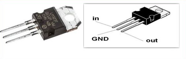
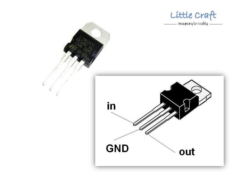
    LM7805 5V voltage regulator
    LM323T voltage regulator IC and pinout

    The voltage regulator IC, L232T is used to provide a regulated 5V DC output. Input voltage fed into the input pin (pin 1) was 2 volts more than the rated output voltage (in our own case 12V) for proper working of Integrated Circuit (IC). For better results, a filter ripple capacitor of 1uF was connected to the output of the IC L323T to eliminate the noise, produced by transient changes in voltage.

    Read Also How to Install CCTV Surveillance Cameras with Remote Viewing

    Datasheet Specifications:

    • Output Voltage: +5V, up to 3A with peak current of 4.5A
    • Current Output: up to 3.5A
    • Input Voltage: 7V Minimum, 35V Maximum
    • Package : TO-220
    • Pin Spacing Pitch : 2.54mm (0.1in)
    • Hole Diameter : 3.8mm (0.15in)
    • STMicroelectronics Part Number:  L323T

    Metal Detector Unit

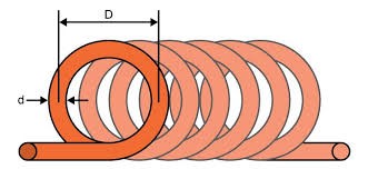
    This unit is mainly composed of the resistor, the inductor and the capacitor used to for the EMF pulsating device. In our design resistor-inductor-capacitive (RLC) circuit, we made us of a hand-made 150 coil turns of size wire gauge 30 wound about a diameter of 6cm to form the EMF emitting part of our design.

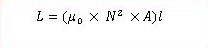
    The whole SMS based Metal detector design depends on us building an LC high pass filter with the help of a coil and a capacitor. According to the equation of Mutual inductance;

    formula for LC calculation
    formula for LC calculation

    Where,

    L is Inductance in Henry

    μo   is permeability, its 4π*10-7 for Air

    N is number of turns of wire coil

    A is inner Core Area (πr2) in m2

    L is length of the Coil in meters

    Whenever a current passes through a coil, it generates a magnetic field around it. And the change in the magnetic field generates an electric field. Now according to Faraday’s law, because of this Electric field, a voltage develops across the coil which opposes the change in magnetic field and that’s how our coil develops the Inductance, means the generated voltage opposes the increase in the current.

    When we place a metal near the coil, the coil changes its inductance. This change in inductance depends upon the metal type. And  for a ferromagnetic material like iron, it increases. However, it decreases for non-magnetic materials.

    The medium of flow of the magnetic field generated by the inductor is nothing in air. Depending on the core of the coil, the inductance value changes drastically.

    The coil wound here is an air cored one, so when we bring a metal piece near the coil, the metal piece acts as a core for the air cored inductor. Hence,  the inductance of the coil changes or increases considerably. With this sudden increase in inductance of coil the overall reactance or impedance of the LC circuit changes by a considerable amount when compared without the metal piece.

    5cm diameter Coil

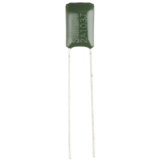
    10nF 100VDC Polyester Capacitor

    10nF polyester capacitor used in the design

    10nF polyester capacitor used in the design

    Polyester capacitors offer good stability and a large range of values at a low cost, and they are used for charging and discharging the inductor in the circuit of How to Build an SMS Based Metal Detector project design.

    How to Build an SMS Based Metal Detector: 330Ω Resistor

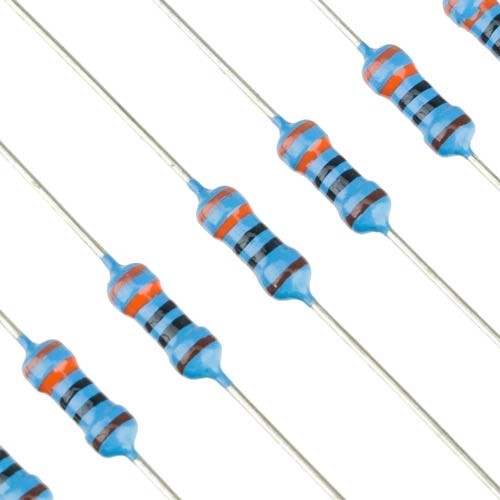
    33K-ohms precision resistor

    330Ω 1/4W Metal Film Precision Resistor

    Specifications:

    • Resistance: 330 Ohms
    • Wattage Rating: 0.25 Watt
    • Tolerance: 1%
    • Metal Film
    • Lead Free
    • ROHS compliant
    • Diameter of Leads: 0.43mm (0.02in)
    • Length of Leads: ~28mm (1.1in)

    IN4148 DIODE

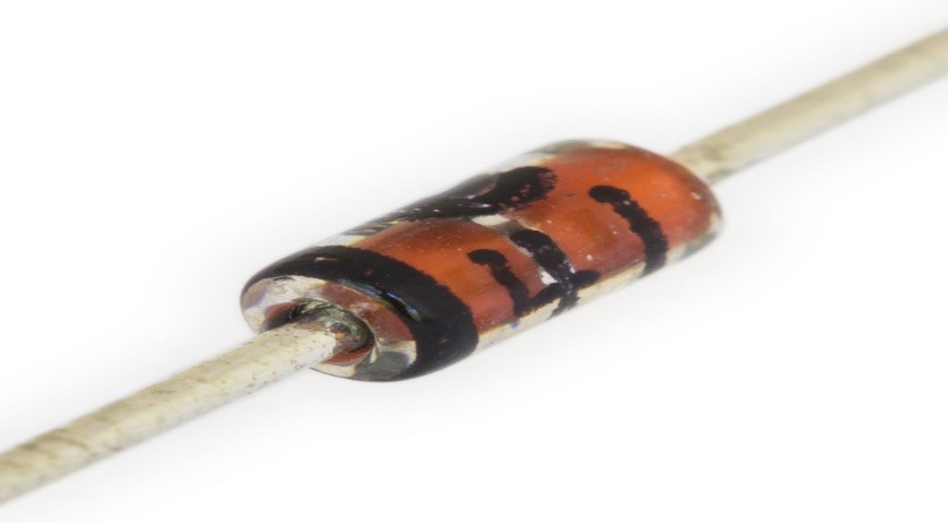
    zener diode
    IN4148 diode

    The 1N4148 is a standard silicon switching signal diode. This diode, 1N4148 can switch within applications of up to about 100 MHz with a reverse-recovery time of no more than 4 ns. It was fabricated in planar technology, and encapsulated in a hermetically sealed leaded glass DO-35 package.

    SIM900L GSM module:

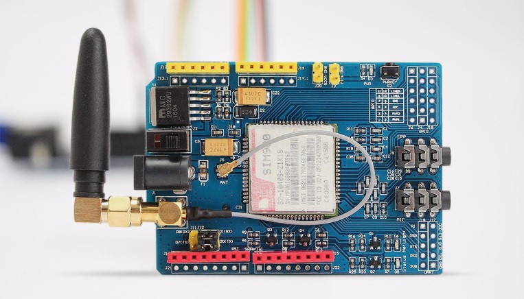
    How to build an SMS based metal detector: SIM900L GSM shield module
    SIM900L GSM shield module

    SIM900L GSM/GPRS shield is a GSM modem. It allows  what a normal cell phone can do: Make or receive phone calls, connect to internet through GPRS, TCP/IP, and more. It supports quad-band GSM/GPRS network, meaning it works pretty much anywhere in the world. The shield itself was designed to surround the SIM900L chip. We needed this module in this How to Build an SMS Based Metal Detector design so that it can allow us send short massage service (SMS) easily.

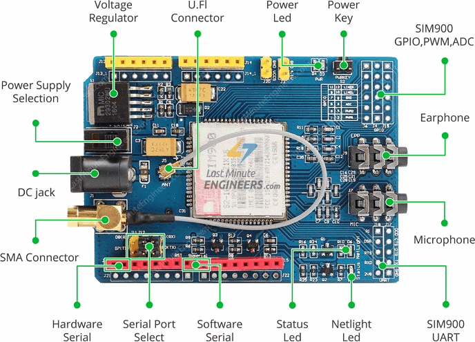
    SIM900L GSM shield module part identification
    pin diagram of SIM900L courtesy of lastminuteengineers

    900L Shield LED Status Indicators

    900L Shield LED Status Indicators:
    900L Shield LED Status Indicators

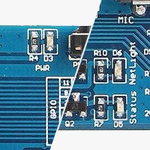
    The LEDs blinking statuses on the SIM900L board has different interpretation. The LEDs on the board is two, namely:

    • PWR: This LED is connected to the shield’s power supply line. If this LED is on, the shield is receiving power.
    • Status: This LED indicates SIM900’s working status. If this LED is on, the chip is in working mode.
    • Netlight: This LED indicates the status of our cellular network. It blinks at various rates to show what state it’s in.
      • off: The SIM900 chip is not running
      • 64ms on, 800ms off: The SIM900L chip is running but not registered to the cellular network yet.
      • 64ms on, 3 seconds off: The SIM900 chip is registered to the cellular network & can send/receive voice and SMS.
      • 64ms on, 300ms off: The GPRS data connection we requested is active.

    How to Build an SMS Based Metal Detector: Powering the SIM900L

    Depending on which state it’s in, the SIM900 can be a relatively power-hungry device. The maximum current draw of the chip is around 2A during transmission burst. It usually won’t pull that much, but may require around 216mA during phone calls or 80mA during network transmissions.

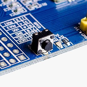
    The power button on the SIM900L GSM module
    The PWRKEY button of the Sim900L

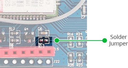
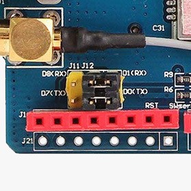
    To use the SIM900L, we hard to turn on the chip. To do this we had to press and hold (for a few seconds) the ON button by the side as shown in the figure above. But we needed to turn on the GSM module every time we power on the design. To do this we had to use the software trigger version of turn on the GSM  module. We first connected the D9 of the SIM900L to D9 of the MCU. Next we soldered the SMD jumper as shown in the figure below:

    GSM module
    the solder jumper to be joined together.

    Interfacing GSM module Sim900L with MCU:

    Using the UART Communication:

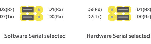
    The SIM900 GSM/GPRS shield uses universal asynchronous receiver-transmitter (UART) protocol to communicate with the MCU. The chip supports baud rate from 1200bps to 115200bps with Auto-Baud detection.

    SMS based metal detector
    Two options of connections: software serial and hardware serial select pins
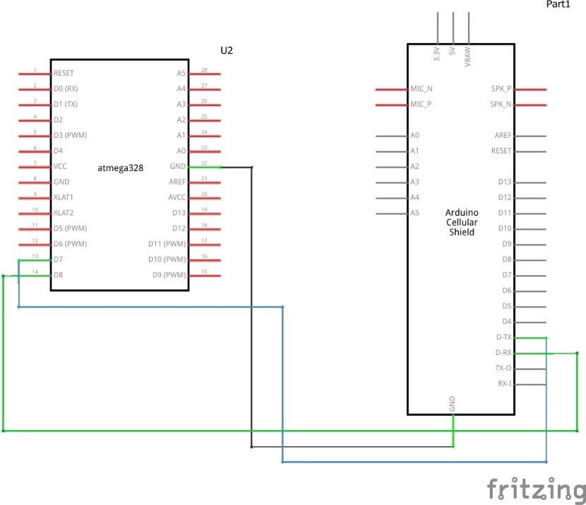
    How to Build an SMS Based Metal Detector: the circuit diagram

    Afer ensuring that the jumper cap is placed on the software serial port select, we connected the MCU according to the circuit diagram shown in figure below.

    How to Build an SMS Based Metal Detector: the circuit diagram
    How to Build an SMS Based Metal Detector: the circuit diagram

    Although the GSM module could also work on 5V DC but we connected the sim900L to an external power of source of not less than 7V 2A supply. The module adjustable voltage regulator makes it possible for it to handle the voltage at this level.

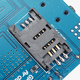
    We used a 2G full sized SIM card and inserted it at the back of the module in its SIM socket. We were careful enough to unlock the latch, push the top part of the assembly, and then lift it up.  We Placed the SIM card into the bottom part of the socket. Then fold the arm back into the body of the socket, and gently push it forward towards the LOCK position.

    The SIM slot
    the SIM slot for SIM900 Module

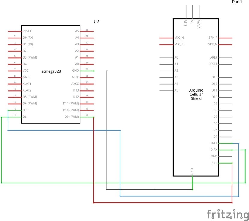
    Hence, the new circuit diagram would be thus:

    How to Build an SMS Based Metal Detector: the circuit diagram
    the connection of the circuit diagram

    5V Passive Buzzer

    piezo speakers or buzzer
    passive buzzer type used in the design

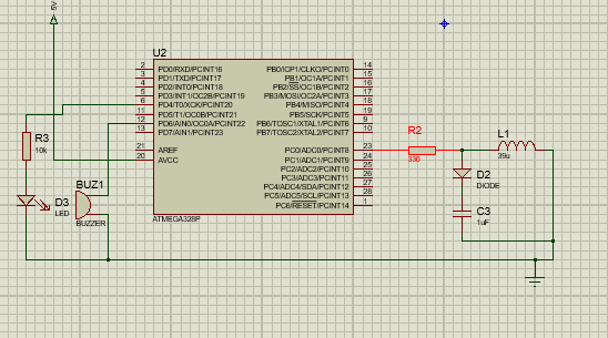
    Generating pulse from the Microcontroller:

    Circuit diagram of the pulse generator for the metal detector
    circuit diagram of the MCU pulse generator

    We send a pulse from our microcontroller to the RL high pass filter, as such, short spikes will be generated by the coil in every transition. The pulse length of the generated spikes is proportional to the inductance of the coil. So with the help of these spike pulses we can measure the inductance of Coil. But here it is difficult to measure inductance precisely with that spikes because that spikes are of very short duration. We used a capacitor to solve this problem which is charged by the rising pulse or spike. And it required few pulses to charge the capacitor to the point where its voltage can be read by analog pin ADC0. And the microcontroller reads the voltage of this capacitor by using ADC syntax. After reading voltage, capacitor quickly discharged since we made it an output and setting it to LOW. This whole process takes around 200 microseconds to complete. For better result, we repeat measurement and took an average of the results. That’s how we can measure the approximate inductance of Coil. After getting the result we transfer the results to the LED and buzzer to detect the presence of metal.

    Arduino Source Code (Sketch)

    In our program for how to build an SMS-based metal detector project design, to be uploaded into the MCU, we created a function where we can turn on the sim900L using a software trigger. The syntax for the program was:

    Testing Attention (AT) Commands:
    For sending AT commands void SIM900power(){
      pinMode(9, OUTPUT); 
      digitalWrite(9,LOW);
      delay(1000);
      digitalWrite(9,HIGH);
    }


    Testing Attention (AT) Commands:

    For sending AT commands and communicating with the SIM900 shield, we will use the serial monitor. Below codes are the the syntax that will enable the MCU to communicate with the SIM900 shield on serial monitor window.

    //since we were using the software serial, we added the library
    #include <SoftwareSerial.h>
    
    //Create software serial object to communicate with SIM900
    //SIM900 Tx & Rx is connected to MCU #7 & #8
    SoftwareSerial mySerial(7, 8); 
    
    void setup()
    {
      //Begin serial communication 
      Serial.begin(9600);
      
      //Begin serial communication with MCU and SIM900
      mySerial.begin(9600);
    
      Serial.println("Initializing...");
      delay(1000);
    
    //Handshaking with SIM900
      mySerial.println("AT");   
    updateSerial();
    //Signal quality test, value range is 0-31 , 31 is the best
      mySerial.println("AT+CSQ"); 
      updateSerial();
    //Read SIM information to confirm whether the SIM is plugged
      mySerial.println("AT+CCID"); 
      updateSerial();
    //Check whether it has registered in the network
      mySerial.println("AT+CREG?");
      updateSerial();
    }
    
    
    void loop()
    {
      updateSerial();
    }
    
    
    void updateSerial()
    {
      delay(500);
      while (Serial.available()) 
      {
    //Forward what Serial received to Software Serial Port
        mySerial.write(Serial.read());
      }
      while(mySerial.available()) 
      {
    //Forward what Software Serial received to Serial Port
        Serial.write(mySerial.read());
      }
    }


    Source Code Explanation

    AT – It is the most basic AT command. It initializes Auto-baud’er.  When this command worked, we saw its characters echo, telling us that it understood us correctly. This paved way for us to use some other commands to query the GSM module and get information like:

    AT+CSQ – meaning check signal strength query; it checks the ‘signal strength’ – the first number is dB strength, it should be higher than around 5. For us, being higher is better. This our length and type of antenna and location played a very vital role in that.

    AT+CCID –  this command gets the SIM card number – it tests that the SIM card is found OK and using it we verified the number written on the card.

    AT+CREG? This command checks if the SIM is on a registered network    Check that you’re registered on the network. The second number should be 1 or 5.  If 1, it showed that our SIM was on a registered home network and 5 indicates roaming network. Any other number than these two numbers showed our SIM was not registered to any network.

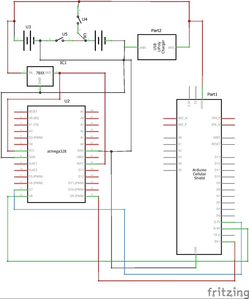
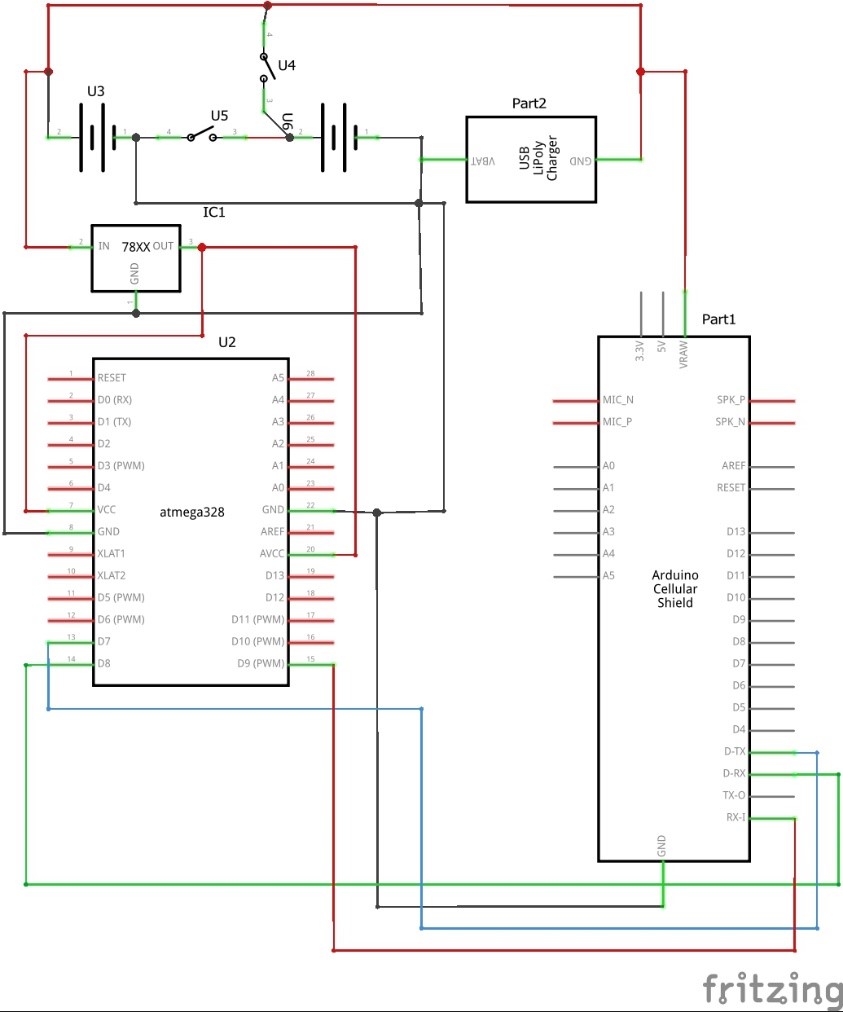
    Internally Charging the LiPo Batteries

    The schematic diagram of the SMS based metal detector design
    The schematic diagram of the SMS based metal detector design

    Circuit Diagram Explanation

    The Power Supply for the design consist of two LiPo 4.2V 3800mAH batteries connected in series. In order to recharge these batteries we had to use a single 4.2 1A charger and connected the outputs in parallel the batteries terminals. But the series connection posed a problem so we had to add two switches that would open the series connection when it is time for charging and close it when we are not charging the batteries as shown above.

    The microcontroller uses 5V DC supply and the 8.4V formed by the series connection of the two batteries would only fry it. So we used a step-down converter of a 78xx series family viz; LM323T. It regulated the input voltage to a steady 5V output at 2A current for the Vcc of the MCU.

    The Complete Source Code

    #include <SoftwareSerial.h>
    
    SoftwareSerial mySerial(7, 8);
    
    int Seven = 10;
    #define capPin A1
    #define buz 11
    #define pulsePin A0
    #define led 12
    #define ledRead 6
    #define led2 5
    
    long sumExpect=0; //running sum of 64 sums
    long ignor=0; //number of ignored sums
    long diff=0; //difference between sum and avgsum
    long pTime=0;
    long buzPeriod=0;
    
     
    void setup()
    {
      mySerial.begin(9600);   // Setting the baud rate of GSM Module  
      Serial.begin(9600);    // Setting the baud rate of Serial Monitor (Arduino)
      pinMode(Seven, INPUT);
      delay(100);
    pinMode(pulsePin, OUTPUT);
    digitalWrite(pulsePin, LOW);
    pinMode(capPin, INPUT);
    pinMode(buz, OUTPUT);
    pinMode(ledRead, INPUT);
    pinMode(led2, OUTPUT);
    digitalWrite(buz, LOW);
    pinMode(led, OUTPUT);
    
    pinMode(9, OUTPUT); 
    //this turns on the sim900 automatcally
      digitalWrite(9,LOW);
      delay(1000);
      digitalWrite(9,HIGH);
      delay(2000);
      digitalWrite(9,LOW);
      //wait for 3sec
      delay(3000);
    }
    
    void SendMessage()
    {
      mySerial.println("AT+CMGF=1");    //Sets the GSM Module in Text Mode
      delay(1000);  // Delay of 1000 milli seconds or 1 second
      mySerial.println("AT+CMGS=\"+2347062174135\"\r"); // Replace this with mobile number
      delay(1000);
      mySerial.println("A METAL HAS BEEN DETECTED,SEARCH VERY WELL ");// The SMS text we sent out
      delay(100);
       mySerial.println((char)26);// ASCII code of CTRL+Z
      delay(1000);
    }
    
    
     void RecieveMessage()
    {
      mySerial.println("AT+CNMI=2,2,0,0,0"); // AT Command to receive a live SMS
      delay(1000);
     }
     
    
    void applyPulses()
    {
    for (int i=0;i<3;i++)
    {
    digitalWrite(pulsePin,HIGH); //take 3.5 uS
    delayMicroseconds(3);
    digitalWrite(pulsePin,LOW); //take 3.5 uS
    delayMicroseconds(3);
    }
    }
    
    
    void loop(){
    int pinSeven = digitalRead(Seven);
    
    if (Serial.available()>0)  { 
        
        }
        
     if(pinSeven == HIGH){
      
      int minval=1023;
    int maxval=0;
    long unsigned int sum=0;
         
      for (int i=0; i<256; i++)
    {
    //reset the capacitor
    pinMode(capPin,OUTPUT);
    digitalWrite(capPin,LOW);
    delayMicroseconds(20);
    pinMode(capPin,INPUT);
    applyPulses();
    //read the charge of capacitor
    int val = analogRead(capPin); //takes 13x8=104 microseconds
    minval = min(val,minval);
    maxval = max(val,maxval);
    sum+=val;
    long unsigned int cTime=millis();
    char buzState=0;
    if (cTime<pTime+10)
    {
    if (diff>0)
    buzState=1;
    else if(diff<0)
    buzState=2;
    }
    if (cTime>pTime+buzPeriod)
    {
    if (diff>0)
    buzState=1;
    else if (diff<0)
    buzState=2;
    pTime=cTime;
    }
    if (buzPeriod>300)
    buzState=0;
    if (buzState==0)
    {
    digitalWrite(led, LOW);
    noTone(buz);
    }
    else if (buzState==1)
    {
    tone(buz,2000);
    digitalWrite(led, HIGH);
    
    }
    else if (buzState==2)
    {
    tone(buz,500);
    digitalWrite(led, HIGH);
    
    }
    
    }
    //subtract minimum and maximum value to remove spikes
    sum-=minval;
    sum-=maxval;
    if (sumExpect==0)
    sumExpect=sum<<6; //set sumExpect to expected value
    long int avgsum=(sumExpect+32)>>6;
    diff=sum-avgsum;
    if (abs(diff)<avgsum>>10)
    {
    sumExpect=sumExpect+sum-avgsum;
    ignor=0;
    }
    else
    ignor++;
    if (ignor>64)
    {
    sumExpect=sum<<6;
    ignor=0;
    }
    if (diff==0)
    buzPeriod=1000000;
    else
    buzPeriod=avgsum/(2*abs(diff));
    }
    
    if((digitalRead(ledRead) ==HIGH) && (pinSeven == HIGH)){
      SendMessage();
      
    }


     else{
          
      }
    
      if (mySerial.available()>0)
       Serial.write(mySerial.read());
    
    }
    

    Why SMS Alerts are Critical in Metal Detectors?

    SMS alerts offer a significant advantage over traditional metal detectors because they provide real-time notifications, even if you’re not physically present. In high-security environments, receiving an SMS immediately after metal detection allows for quicker action and response. For example, in an airport setting, SMS alerts can notify the security team about unauthorized metal objects, reducing the chances of a security breach.

    Enhancing the SMS-Based Metal Detector

    If you want to take this project to the next level, here are some advanced features you can consider:

    • Integrating IoT: By connecting your system to a cloud platform, you can monitor detections remotely and maintain a database of all alerts.
    • Multiple Sensors: Add more metal detection sensors to cover larger areas.
    • Security Cameras: Integrate a camera to capture images or video whenever metal is detected.

    Practical Applications of an SMS-Based Metal Detector

    • Public Security: Ideal for airports, malls, or other places with high foot traffic.
    • Private Security: Use in homes, offices, or businesses to prevent unauthorized metallic objects from entering.
    • Industrial Use: Detecting metal theft or unauthorized tools in warehouses or factories

    Challenges and How to Overcome Them

    Detection Range Issues

    • Ensure that the sensor’s range is appropriate for your application. If the sensor is too sensitive or not sensitive enough, recalibrate it or consider using a different sensor.

    Power Supply Limitations

    • If you’re using the system in a remote location, consider using a solar panel or a larger battery to provide continuous power.

    False Alarms

    • To reduce false positives, make sure the sensor is properly calibrated and placed in an area where there is minimal metal interference.

    Conclusion

    We have done justice to the design of how to build an SMS-based metal detector project. What do you think? Can you build similar a project design? Let us know in the comment section if you followed this guide to achieve a successful project work. You can contact us and send us pictures and videos of your project design on WhatsApp, Twitter, Telegram, Instagram to and send us pictures or ask questions too.

    Read More

    Frequently Asked Questions (FAQs)

    Can I use this system for detecting other materials besides metal?

    • No, this system is specifically designed to detect metals. Different sensors would be required for other materials.

    How do I troubleshoot when my system doesn’t send SMS alerts?

    • Check the GSM module connections, ensure the SIM card has sufficient balance, and verify the network signal.

    Can I use a different Arduino board besides Arduino Uno?

    • Yes, you can use other Arduino boards like Nano or Mega, but the code and wiring may need minor adjustments.

    How far can the metal detector sense metal objects?

    • The detection range depends on the type of sensor used, typically ranging from a few centimeters to several meters.

    Is it possible to integrate this system with a security camera?

    • Yes, you can connect this system with a security camera by adding a relay module that triggers the camera when metal is detected.
  • How to design Motion Detector Smart Street Lights System.

    How to design Motion Detector Smart Street Lights System.

    The goal of the project on “How to Design Motion Detector Smart Street Lights System is to control the amount of energy used when illuminating the pathways for motorists and pedestrians alike at night. At night, a lot of energy is usually used up to keep the street lights on all night. Most of the time, the illumination on these paths is not necessarily needed as there will be nobody using the roads. This project demonstrates how to design a motion detector smart street light system project so that it is smart enough to notice the movement of objects around it and light up the path so that people can see properly.

    Introduction to Smart Street Lights

    Motion Detector Smart Street Lights System
    Motion Detector Smart Street Lights System

    Smart street lights are an innovative solution designed to enhance urban infrastructure by integrating advanced technologies into traditional street lighting systems. These lights are equipped with sensors, communication modules, and control systems that allow them to operate more efficiently and adapt to real-time conditions. By leveraging technologies such as IoT (Internet of Things), smart street lights can adjust their brightness based on ambient light levels, detect motion, and even communicate with other smart devices. This not only improves energy efficiency but also enhances public safety and reduces maintenance costs.

    Importance of Motion Detection in Street Lighting

    Motion detection is a crucial feature in smart street lighting systems as it significantly contributes to energy conservation and public safety. By using motion sensors, such as Passive Infrared (PIR) sensors, street lights can automatically illuminate when they detect movement, ensuring that areas are well-lit only when necessary. This targeted lighting approach reduces energy consumption by preventing lights from being on continuously, thereby lowering electricity costs and minimizing environmental impact. Additionally, motion-activated lights can deter criminal activities and enhance the safety of pedestrians and drivers by providing adequate illumination only when needed.

    Materials/Components

    This smart street light control system project makes use of the Atmega328P-PU microcontroller, a motion detector sensor like a PIR sensor, and some AC light bulbs to sense the presence of pedestrians and illuminate their paths for them. For this project, we are going to need the following materials:

    • 12v solid state relays………………………………………………………3pcs
    • Atmega328P-PU microcontroller…………………………………….1pcs
    • AC light bulbs 220/240V 200W………………………………………3pcs
    • 12V power adapter………………………………………………………1pcs
    • 5V or 12V 3-channel relay module……………………………………………….1pcs

    You can buy the complete kit from our online store. or chat with us privately on WhatsApp.

    The Circuit Diagram

    To begin, we need to construct our MCU board. Read this previous post of ours to know how to build your own working standalone Arduino board. It would be very wise, however, to make sure that the power supply unit or DC supply adapter outputs enough current to power all the parts that run on DC.

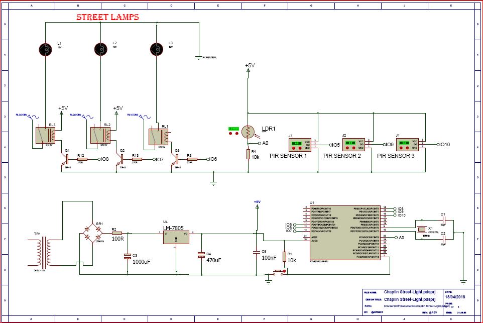
    how to design motion detector smart street lights circuit diagram
    Motion detector smart street lights circuit diagram

    Circuit Diagram Explanation

    From the street light sensor circuit above, the power supply is producing 5V at 1A for the MCU, PIR sensors, and the 5V 3-channel relay module.

    The MCU board is configured to control the 3-channel relay module through input/output (IO) pins 5, 6 and 7 respectively. While the PIR sensors are controlled via IO pins 8, 9 and 10 respectively.

    The LDR sensor for this street light (Light Dependent Resistor), which we used here as optical sensor to differentiate when it is dark and when it is daytime, is connected to analog input pin 0 (A0) but voltage divider theorem (since the LDR is connected in series with a 10kΩ fixed resistor). The whole idea of this connection is to measure the rate of change in analog voltage as the resistance of the LDR changes due to the amount of light on its surface. The type of LDR used in this how to design motion detector smart street light system project has a negative coefficient of resistance; which means that as the amount of light on its flat surface increases, the resistance across it decreases.

    read also Receding Hairline 101: Causes, Solutions, and Tips for Prevention

    Source Code (Arduino Sketch)

    The how to design motion detector smart street light system project would achieve its objective only when it is dark and when there is motion around it that needs to use the illumination it would give out. Hence, we write our program for the smart street project on the Arduino platform again as:

    //Arduino source-code for Motion Detector Smart Street Light System project//
    //the time we give the sensor to calibrate (10-60 secs according to the datasheet)
    int calibrationTime = 10;    
    
    //the time when the sensor outputs a low impulse
    long unsigned int lowIn;        
    //the amount of milliseconds the sensor has to be low 
    //before we assume all motion has stopped
    long unsigned int pause = 200;  
    
    boolean lockLow = true;
    boolean takeLowTime; 
    
    //the digital pin connected to the PIR sensor's output
    int pirPin1 = 10; 
    int pirPin2 = 11;
    int pirPin3 = 12;
    int relay1 = 7;
    int relay2 = 8;
    int relay3 = 9;
    int LDRVcc = 6;
    
    
    void setup() {
    /*we declare the input and output pins of the sensors 
    and actuators connected to d MCU */
    
      pinMode(pirPin1, INPUT);
      pinMode(pirPin2, INPUT);
      pinMode(pirPin3, INPUT);
      pinMode(relay1, OUTPUT);
      pinMode(relay2, OUTPUT);
      pinMode(relay3, OUTPUT);
    pinMode(LDRVcc, OUTPUT);
    
    //we wanted the LDR to kick start when the MCU is up and running, 
    //hence, we energized with one of the IO pins of the MCU.
    //using a HIGH command
     digitalWrite(LDRVcc, HIGH);
    //we start the serial monitor to see the readings of the sensors
     Serial.begin(9600); 
     //give the PIR sensor some time to calibrate
      Serial.print("calibrating sensor ");
    //for the calibration sequence that is displaying, we used a for loop
        for(int i = 0; i < calibrationTime; i++){
          Serial.print(".");
          delay(50);
    }
    }
    
     
     void loop(){
      //We start reading signals from the LDR connected to analog pin 0.
      int lightSense = analogRead(0);
    //we print these readings on the serial monitor
      Serial.println(lightSense);
    //with a delay of 0.5s between each value displayed
      delay(500);
    //Using a simple if-statement we 
      if(lightSense <= 300) {
        if(digitalRead(pirPin1) == HIGH){
    //the led visualizes the sensors output pin state
           digitalWrite(relay1, HIGH);   
           if(lockLow){  
             //makes sure we wait for a transition to LOW before any further output is made:
             lockLow = false;            
            
             }         
             takeLowTime = true;
        }
    
    else if(digitalRead(pirPin1) == LOW){       
           digitalWrite(relay1, LOW);  //the led visualizes the sensors output pin state
    
           if(takeLowTime){
            lowIn = millis();          //save the time of the transition from high to LOW
            takeLowTime = false;       //make sure this is only done at the start of a LOW phase
            }
           //if the sensor is low for more than the given pause, 
           //we assume that no more motion is going to happen
           if(!lockLow && millis() - lowIn > pause){  
               //makes sure this block of code is only executed again after 
               //a new motion sequence has been detected
               lockLow = true;                        
               
               }
           }
    
           if(digitalRead(pirPin2) == HIGH){
           digitalWrite(relay2, HIGH);   //the led visualizes the sensors output pin state
           if(lockLow){  
             //makes sure we wait for a transition to LOW before any further output is made:
             lockLow = false;            
            
             }         
             takeLowTime = true;
    
        }
    else if(digitalRead(pirPin2) == LOW){  
    //the led visualizes the sensors output pin state
           digitalWrite(relay2, LOW);  
           if(takeLowTime){
    //save the time of the transition from high to LOW
            lowIn = millis();      
    //make sure this is only done at the start of a LOW phase    
            takeLowTime = false;               }
           //if the sensor is low for more than the given pause, 
           //we assume that no more motion is going to happen
           if(!lockLow && millis() - lowIn > pause){  
               //makes sure this block of code is only executed again after 
               //a new motion sequence has been detected
               lockLow = true;                        
               
               }
           }
    
    if(digitalRead(pirPin3) == HIGH){
           digitalWrite(relay3, HIGH);   //the led visualizes the sensors output pin state
           if(lockLow){  
             //makes sure we wait for a transition to LOW before any further output is made:
             lockLow = false;            
            Serial.println("---");
            Serial.print("motion detected at ");
             Serial.print(millis()/1000);
             Serial.println(" sec"); 
             delay(50);
             }         
             takeLowTime = true;
    
        }
    
    else if(digitalRead(pirPin3) == LOW){  
    //the led visualizes the sensors output pin state     
           digitalWrite(relay3, LOW);  
    
           if(takeLowTime){
    //save the time of the transition from high to LOW
            lowIn = millis();   
    //make sure this is only done at the start of a LOW phase       
            takeLowTime = false;       
            }
           //if the sensor is low for more than the given pause, 
           //we assume that no more motion is going to happen
           if(!lockLow && millis() - lowIn > pause){  
               //makes sure this block of code is only executed again after 
               //a new motion sequence has been detected
               lockLow = true;                        
               
               }
           }
        delay(50);
      }
       
      
      if (lightSense >= 301 ) {
        digitalWrite(relay1, LOW);
        digitalWrite(relay2, LOW);
        digitalWrite(relay3, LOW);
        if(takeLowTime){
    //save the time of the transition from high to LOW
            lowIn = millis(); 
    //make sure this is only done at the start of a LOW phase         
            takeLowTime = false;       
            }
           //if the sensor is low for more than the given pause, 
           //we assume that no more motion is going to happen
           if(!lockLow && millis() - lowIn > pause){  
               //makes sure this block of code is only executed again after 
               //a new motion sequence has been detected
               lockLow = true;                        
               
    
      }
    
      }
     }


    Further Explanation of Arduino Sketch:

    We declared all our variables from line 3 through line 21, the calibration time  for the PIR sensors was to 10 seconds according to the datasheet of the product. But the sensor emits a pulse and waits for an obstacle to reflect it by cutting into its line of projection. So we used a long variable unsigned to denote this. In the loop function, we have already noticed that during dark, the LDR displays values that are below 300 and when it experiences sufficient amount across its surface, its values rises way above 300. Using the if-statement we made a comparison as regards to when the latter following lines would be executed. The rest of the algorithm used for the Motion Detector Smart Street Lights System project are explained using comment line. And notice there is a repeated pattern for the three PIRs.

    Connecting the AC Lamps

    The AC bulbs are connected as shown in the circuit diagram. The relays: relay1, relay2 and relay3 acts as the bridge between the DC and the AC voltage. In other words for the AC bulbs to be turned on, the relays must be energized. The relay energizing voltages were rated 5V but 12V solid state relays are recommended to avoid arching between switching poles of the relays and burning out the filaments of the tungsten bulbs.  A better choice would to go for energy saving lamps that uses AC to DC converters.

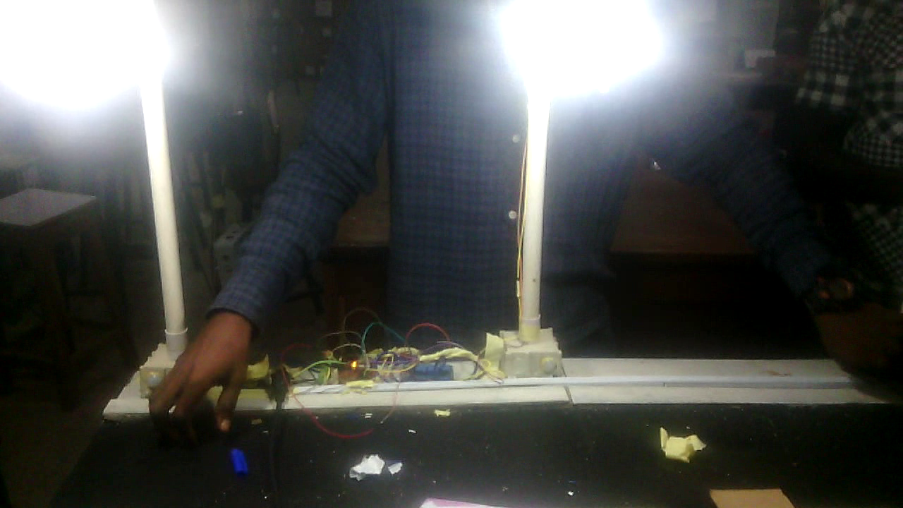
    The working video is shown in the embed YouTube below.

    The working video of the Motion Detector Smart Street Lights System project

    The video demonstration shows that the model for this project was done on a copy off of a major type A road that has motion sensors attached to the base of each street light system. when movement was sensed, these street light come on and would go off in the absence of motion. The model was portable and made to be easily set up in less time frame.

    Conclusion

    We have done justice to How to design motion detector smart street lights system. What do you think? Can you build similar a project design? Let us know in the comment section if you followed this guide to achieve a successful project work. You can contact us and send us pictures and videos of your project design on WhatsApp, Twitter, Telegram, Instagram to and send us pictures or ask questions too.

    Read More

    FAQs

    Q1: Can this system work outdoors?
    Yes, but the PIR sensor must be weatherproof.

    Q2: Can solar power be used?
    Absolutely. A solar panel + battery makes it perfect for outdoor areas.

    Q3: Does the system detect animals?
    Yes. PIR sensors detect heat signatures from humans and animals.

    Q4: Can this system be expanded?
    Yes — IoT features (ESP32/NodeMCU) can be added to monitor lights remotely

  • How to Build a Wi-Fi based Smart Farm Monitoring System Project.

    How to Build a Wi-Fi based Smart Farm Monitoring System Project.

    smart farm monitoring system
    smart farm monitoring system

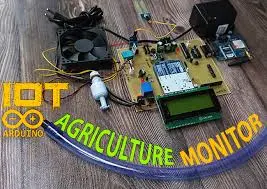
    In this how to build a Wi-Fi based smart farm monitoring system project tutorial, we are going to be using ESP8266 Wi-Fi Module to create a wireless access point to view some farm parameters on a home garden model. We are going to be measuring soil moisture content, digital humidity and temperature readings of the green plants in the model garden. This smart agricultural monitoring system, using Arduino design, should also be able to notice when there is night time so that it can activate a grow lamp that can enhance further growth of the garden plants. So, in this Wi-Fi based Smart Farm Monitoring System project; we aim to achieve the following:

    • Design a system that can measure the temperature around the environment of the plants and display this reading on a digital screen like the 16×2 LCD and also display it on a remote viewing mobile phone screen via Wi-Fi connection.
    • The Wi-Fi based Smart Farm Monitoring System Project would be capable to take humidity readings around the plants and also the soil moisture content the plants.
    • If these parameter readings are insufficient for the sustenance of the garden lives, the design is supposed to automatically adjust and compensate for that change. For example, if the soil moisture content is a little too dry above average reading; a DC pump would be turn on to water the plants automatically.
    • Increase in temperature and thin air around the plants are also controlled with by letting water spray in the garden automatically.
    • The whole system has a remote Wi-Fi based Control system that allows the user to controlled the Wi-Fi based Smart Farm Monitoring System Project using an Android smart phone.

    Materials for the Project

    smart farm monitoring system 2
    smart farm monitoring system 2

    For Power Supply design

    • 12V, 2A step-down transformer………      1pcs
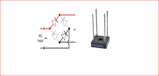
    • Bridge rectifier………………………………..       1pcs

    Capacitors:

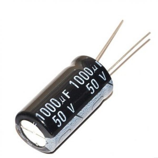
    • 4700µF                                                 2pcs
    • 470µF                                                   2pcs
    • 330µF                                                   2pcs
    • 100µF                                                   2pcs
    • 22pF                                                     2pcs
    • Voltage regulator LM317                              1pcs
    • Voltage regulator LM7805 (or LM232T)   1pcs

    Resistors:

    • 100Ω 5W                                              2pcs
    • 1kΩ Potentiometer                         2pcs
    • 270Ω                                                      2pcs
    • 10kΩ                                                      4pcs
    • 10kΩ Potentiometer                      1pcs
    • LDR                                                        1pcs

    Alternatively, you can get a SMPS with 12V, ≥ 3A with two DC-DC buck converters. Regulate 1 DC-DC buck converter to output 12V and the other to source 5V respectively.

    • Transistor TIP41                                                2pcs
    • 5V Relay                                                               1pcs
    • Soil Moisture sensor module                      1pcs
    • Humidity Sensor DHT11                                 1pcs
    • Wi-Fi module ESP8266                                   1pcs
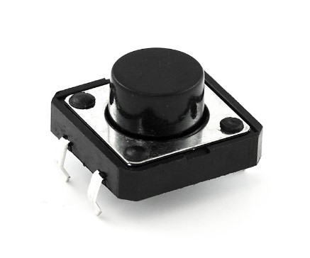
    • Push button                                                       1pcs
    • 12V DC pump                                                     1pcs
    • 16×2 LCD                                                              1pcs
    • 16Mhz Crystal oscillator                                 1pcs
    • Atmega328P-PU                                               1pcs

    The Circuit Diagram

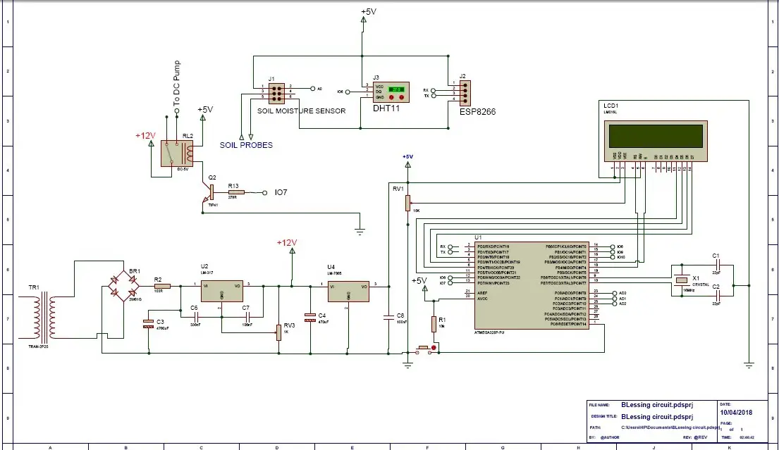
    how to build Wi-Fi based Smart Farm Monitoring System circuit diagram
    Wi-Fi based Smart Farm Monitoring System circuit diagram

    The Circuit Diagram Explanation

    The circuit diagram is built around the Atmega328P-PU Chip and where the 16MHz crystal is connected, the ceramic capacitors connected too. In this standalone version design of Arduino, the pushbutton was used to reset the program.

    The microcontroller was powered by a 5V from a 5V linear power supply. The same 5V was used to power the DHT11 sensor, the 5V relay module, soil moisture sensor and a 3.3V regulator that powers the ESP8266-01 (ESP-01).

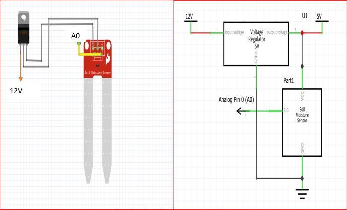
    The Soil Moisture Sensor Circuit Connection:

    How to Build a Wi-Fi based Smart Farm Monitoring System Project
    Picture and circuit diagram of soil moisture sensor

    From the breadboard version and circuit diagram shown above, the humidity sensor is connected to the output pin of the 5V voltage regulator, and the signal pin is connected to the analog pin 0 of the Atmega328P-PU IC.

    The Arduino Source Code (Sketch)

    The following source code is coded into the Arduino IDE to effectively use the soil moisture sensor for the how to build a Wi-Fi based smart farm monitoring system.

     /*PROGRAM TO TEST AND ADJUST THE SOIL ,MOISTURE CONTENT FOR WI-FI BASED SMART FARM MONITORING SYSTEM PROJECT */
    double sensor;
     void setup() {
    Serial.begin(9600);
    }
    
    void soilMonitor() {
      // read the input on analog pin 0:
     sensor = analogRead(A0);
      // Convert the analog reading (which goes from 0 - 1023) to a range (0 - 100):
      double TP = map(sensor, 0.00, 1023.00, 100.00, 0.00);
    serial.println(TP);
    delay(500);
    }
    void loop() {
    soilMonitor();
    }


    Source Code Explanation

    To set and set the proper soil moisture content for our plants in the model garden, we code these syntax into the Arduino IDE, verify it for errors and upload it into out standalone MCU. We then open our serial monitor window and ensure that the communication between the MCU and the PC is set at 9600 baud rate as stated in the setup function.

    We would see the readings on the serial monitor and we could calibrate them using the onboard potentiometer on the soil moisture sensor board.

    In the first line, we declared the sensor read as a double because we are expecting floating point readings from the sensor. In the setup function, we started the serial communication to start displaying readings on the serial monitor screen. We created our own function soilMonitor() to read the signal the sensor pin connected to A0 of the MCU. We then mapped this reading such that the analog reading from the MCU which is  from 0 to 1023 is mapped from 100 to 0. This means that; a value of 0.00 (since the reading is a floating point number) of the soil moisture sensor gets converted to 100.00 and the value of 1023.00 gets converted to 0.00.

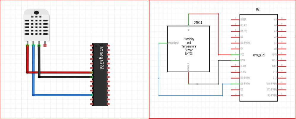
    Humidity and Temperature sensor DHT11 circuit connection:

    DHT11 connection to Atmega328P-PU
    DHT11 connection to Atmega328P-PU

    The DHT11 sensor is connected as shown in the the circuit diagram above, the pin 3( the data signal pin) of the the DHT11 is connected to pin 12 of the Atmega328P-PU IC while the Vcc and the GND pin are connected the 5V and the GND of the power supply. Which is also where the pin 7 and 8 of the Atmega328P-PU has option for the Vcc and the GND. The following sketch below is uploaded into the Arduino IDE to check and test for the accurate reading of the digital humidity and temperature sensor.

    //Import  the DHT11 libs
    #include <DHT.h>
    #include <DHT_U.h>
    // what digital pin are we connecting the DHT11 signal pin on the Atmega328
    #define DHTPIN 6   
    // Define the type of dht you're using!
    #define DHTTYPE DHT11  
    DHT dht(DHTPIN, DHTTYPE);
    void setup() {
    //begin the dht
    dht.begin();
    }
    void loop() {
    float h = dht.readHumidity();
      // Read temperature as Celsius (the default)
      float t = dht.readTemperature();
     int Temp = t;
     int Hum = h;
    //print it out on the serial monitor window
    serial.print(Hum);
      serial.print(Temp);
    //delay for half a sec
    delay(500);
    }


    Connecting your ESP8266 Wi-Fi Module as an access point:

    The ESP8266 module will be configured as a standalone WiFi access point in this Wi-Fi based smart farm monitoring system project. This means there will be no binding to an existing Wi-Fi network that is to be required for its mode of operation. To connect, the smartphone must be connected to the created access point though.

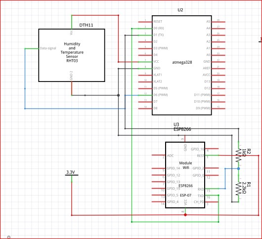
     The circuit diagram shows the connection of the ESP8266 to the Atmega328P-PU as well as the DHT11.

    DHT11 and ESP8266 circuit connection to Atmega328P-PU
    DHT11 and ESP8266 circuit connection to Atmega328P-PU

    Creating your Remote Control Wi-Fi App using RemoteXY Graphical User Interface

    For how to create a free GUI app using RemoteXY and Arduino to control home appliances, read this post.

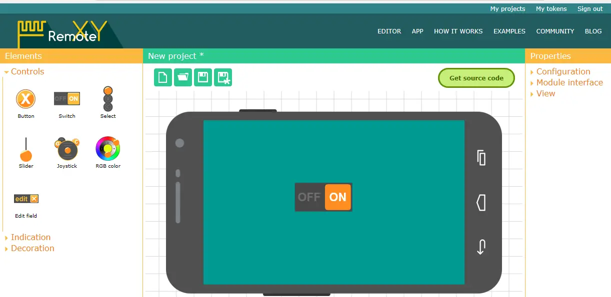
    Open the RemoteXY editor by logging onto their webpage. We would advise creating an account so that your projects can be saved for future reference. Start your new project design. Name it what you will like. In our case, since this project was inspired by Dami, a final year student at landmark varsity, we just simply named it DAMI FARM.

    How to Build a Wi-Fi based Smart Farm Monitoring System Project: RemoteXY new project with Switch
    RemoteXY new project with Switch

    Next we selected a switch button for the user to manually turn on or off the DC pump when he or she feels like the parameters on the screen.

    RemoteXY new project with Switch

    Highlight this switch button, then select the “Snap to pin” property to 7 (DC pump connection) value in the right pane of the “Element” tab.

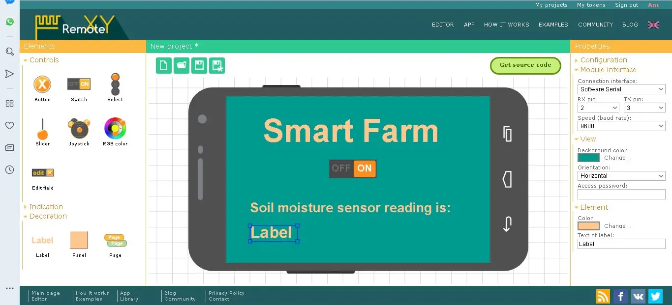
    Again, drag a label and name it the project name. in this project, we had it as Smart farm as the caption just above it all.

    RemoteXY label
    RemoteXY label

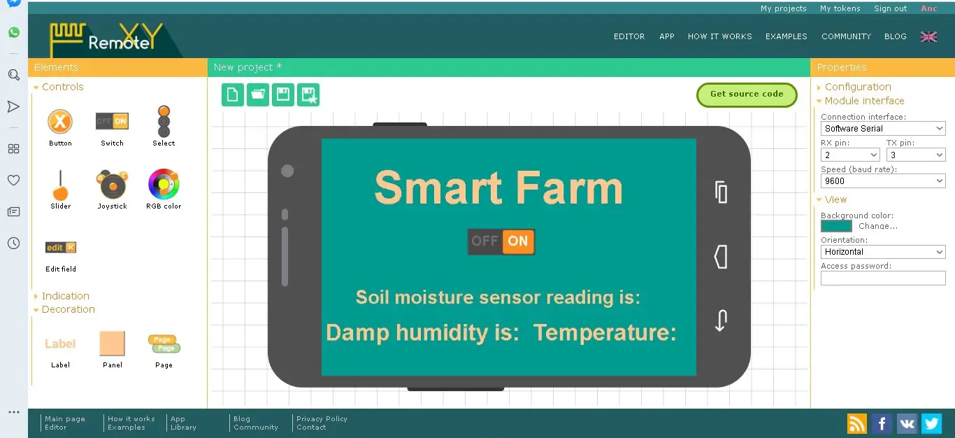
    Add two more labels to the under the switch button icon and edit these labels as shown below.

    How to Build a Wi-Fi based Smart Farm Monitoring System Project
    Two more labels added to the switch button icon
    Editing the labels for sensor readings
    Editing the labels for sensor readings

    Click on each label and expand it. Go to the right pane in the Element column and in the “Text of label” edit the content to the one shown above.

    RemoteXY labels are given spaces to fit in the sensor readings
    The labels are given spaces to fit in the sensor readings

    Then move to the right pane, under the configuration tab, and select ESP8266 Wi-Fi. In that same pane, click on the “module interface” and set the connection interface as the hardware serial. This means we would use the RX and TX pins on the MCU. The speed should be set at a 115200 baud rate. A password should be set  for the Wi-Fi access point in the password box as well as the future Wi-Fi access point name.

    By clicking on the download code link, you will be taken to a page where you can download the source code. Open this in your Arduino IDE, download the remoteXY library and install it correctly.

    To view the farm parameters of the How to Build a Wi-Fi based Smart Farm Monitoring System Project on the place where the design is mounted, we have to include an LCD on the project box. This means we have to code the LCD to display these readings.

    The Complete Sketch:

    //include the lcd lib
    #include <LiquidCrystal.h>
    //include the adafruit lib for dht11
    #include <Adafruit_Sensor.h>
    //include the dth11 lib
    #include <DHT.h>
    #include <DHT_U.h>
    /*
       -- Smart Farm --
       
    */
    // RemoteXY select connection mode and include library 
    #define REMOTEXY_MODE__ESP8266_HARDSERIAL_POINT
    //include the remotexy lib
    #include <RemoteXY.h>
    
    // RemoteXY connection settings 
    #define REMOTEXY_SERIAL Serial
    #define REMOTEXY_SERIAL_SPEED 115200
    #define REMOTEXY_WIFI_SSID "DAMI FARM"
    #define REMOTEXY_WIFI_PASSWORD "12345678"
    #define REMOTEXY_SERVER_PORT 6377
    // RemoteXY configurate  
    #pragma pack(push, 1)
    uint8_t RemoteXY_CONF[] =
      { 255,1,0,47,1,85,0,8,45,2,
      2,1,37,28,16,8,20,31,26,12,
      2,32,31,31,79,78,0,79,70,70,
      0,67,0,1,40,98,6,1,59,61,
      7,31,26,101,67,0,1,48,98,6,
      1,73,61,7,2,26,101,67,0,1,
      56,98,6,1,88,61,7,13,26,101,
      129,0,6,2,89,16,5,5,55,10,
      2,83,109,97,114,116,32,70,97,114,
      109,0 };
      
    // this structure defines all the variables of your control interface 
    struct {
    
        // input variable
      uint8_t SW1; // =1 if switch ON and =0 if OFF 
    
        // output variable
      char SCREEN1[101];  // string UTF8 end zero 
      char SCREEN2[101];  // string UTF8 end zero 
      char SCREEN3[101];  // string UTF8 end zero 
    
        // other variable
      uint8_t connect_flag;  // =1 if wire connected, else = 0
    } RemoteXY;
    #pragma pack(pop)
    
    /////////////////////////////////////////////
    //           END RemoteXY include          //
    /////////////////////////////////////////////
    
    #define PIN_SW1 7
    
    // what digital pin we're connected to
    #define DHTPIN 6    
    
    // Uncomment whatever type you're using!
    #define DHTTYPE DHT11   // DHT 11
    
    
    DHT dht(DHTPIN, DHTTYPE);
    
    // initialize the library with the numbers of the interface pins
    LiquidCrystal lcd(12, 11, 5, 4, 3, 2);
    void setup() 
    {
      RemoteXY_Init (); 
      
      pinMode (PIN_SW1, OUTPUT);
      
    dht.begin();
      lcd.begin(16, 2);
      // Print a message to the LCD.
      lcd.print("Smart FARM Project");
      lcd.setCursor(1,4);
      lcd.print("by DAMILOLA");
      delay(3000);
      lcd.clear();
    }
    void soilMonitor() {
      // read the input on analog pin 0:
      double sensor = analogRead(A0);
      // Convert the analog reading (which goes from 0 - 1023) to a range (0 - 100):
      double TP = map(sensor, 0, 1023, 100, 0);
     //dtostrf(TP, 0, 2, RemoteXY.SCREEN2);//SEND VALUE OF ADC TO SMART PHONE
    
    int soil = TP;
    if((soil < 40) || (soil == 40)  && (RemoteXY.SW1 == 0) ) {
      digitalWrite(PIN_SW1, HIGH);
     strcpy (RemoteXY.SCREEN3, "Pump in AUTO Mode");
    }
    }
    
    void loop() 
    { 
      RemoteXY_Handler ();
      
    soilMonitor();
       // read the input on analog pin 0:
      double sensor = analogRead(A0);
      // Convert the analog reading (which goes from 0 - 1023) to a range (0 - 100):
       double TP = map(sensor, 0, 1023, 100, 0);
     //dtostrf(TP, 0, 2, RemoteXY.SCREEN2);//SEND VALUE OF ADC TO SMART PHONE
    
    int soil = TP;
    
    //sprintf (RemoteXY.SCREEN2, "The Temperature is: %d'C___Farm Humidity is: %d", TEMP, HUM);
    sprintf (RemoteXY.SCREEN1, "The Soil moistue reading is: %d", soil);
    
    if ((soil < 60) && (RemoteXY.SW1 ==1))
    {
    digitalWrite(PIN_SW1, HIGH);
     strcpy (RemoteXY.SCREEN3, "Manual Override: Pump Pumping");
    }
    if ((soil > 40) && (soil < 60) && (RemoteXY.SW1 == 0))
    {
    digitalWrite(PIN_SW1, LOW);
     strcpy (RemoteXY.SCREEN3, "Pump is shut-off");
    }
    if((soil > 60) && (RemoteXY.SW1 ==1)) {
      digitalWrite(PIN_SW1, LOW);
      strcpy (RemoteXY.SCREEN3, "Warning! Farm Flooded, System AUTO Shut Off pump");
    }
    if((soil > 60) && (RemoteXY.SW1 ==0)) {
      digitalWrite(PIN_SW1, LOW);
      strcpy (RemoteXY.SCREEN3, "Thanks, Farm Flooding Averted.");
    }
    
      float h = dht.readHumidity();
      // Read temperature as Celsius (the default)
      float t = dht.readTemperature();
     int Temp = t;
     int Hum = h;
       // Check if any reads failed and exit early (to try again).
      if (isnan(h) || isnan(t)) {
        strcpy (RemoteXY.SCREEN2, "Warning!!! Failed to read from DHT sensor!");
        return;
      }
    sprintf (RemoteXY.SCREEN2, "Farm Humidity is: %d, Temperature is: %d'C", Hum, Temp);
    
    lcd.setCursor(0,0);
      lcd.print("HUM: TEMP: SOIL:");
      lcd.setCursor(2,1);
      lcd.print(Hum);
      lcd.setCursor(7,1);
      lcd.print(Temp);
      lcd.setCursor(13,1);
      lcd.print(soil);
    }


    The RemoteXY APP

    To communicate wirelessly in this How to Build a Wi-Fi based Smart Farm Monitoring System Project; Go to the website or Playstore to download the remoteXY app.

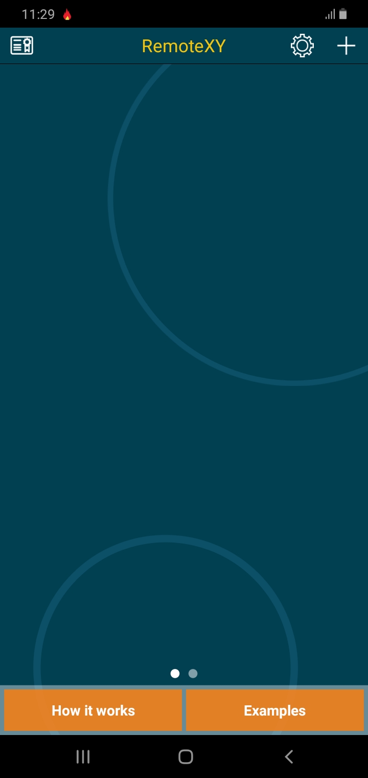
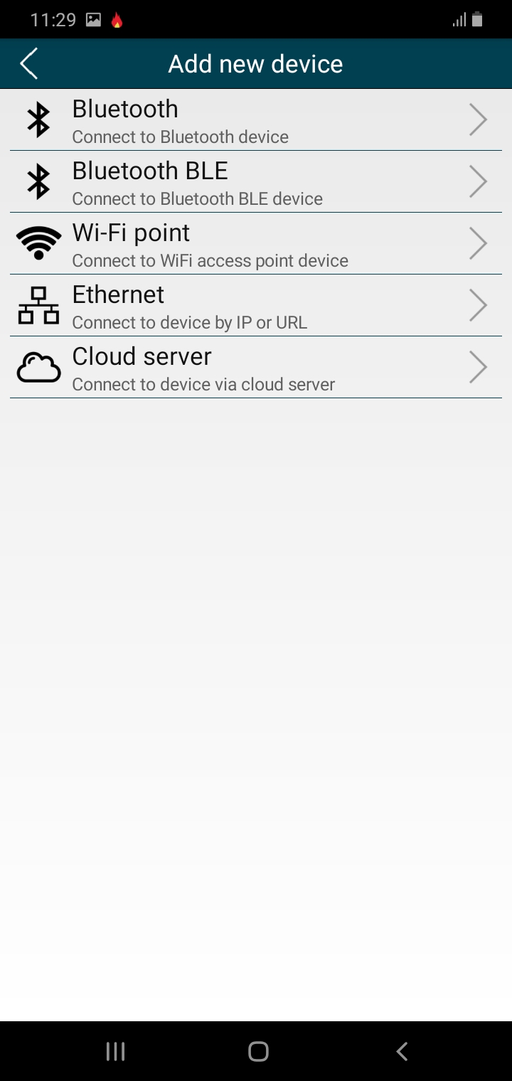
     Run your sketch and then open the app and click on the add or (+) button.

    How to Build a Wi-Fi based Smart Farm Monitoring System Project: The remoteXY app mobile interface
    The remoteXY app mobile interface

    Click on the Wi-Fi access point option available in the lists of options.

    How to Build a Wi-Fi based Smart Farm Monitoring System Project

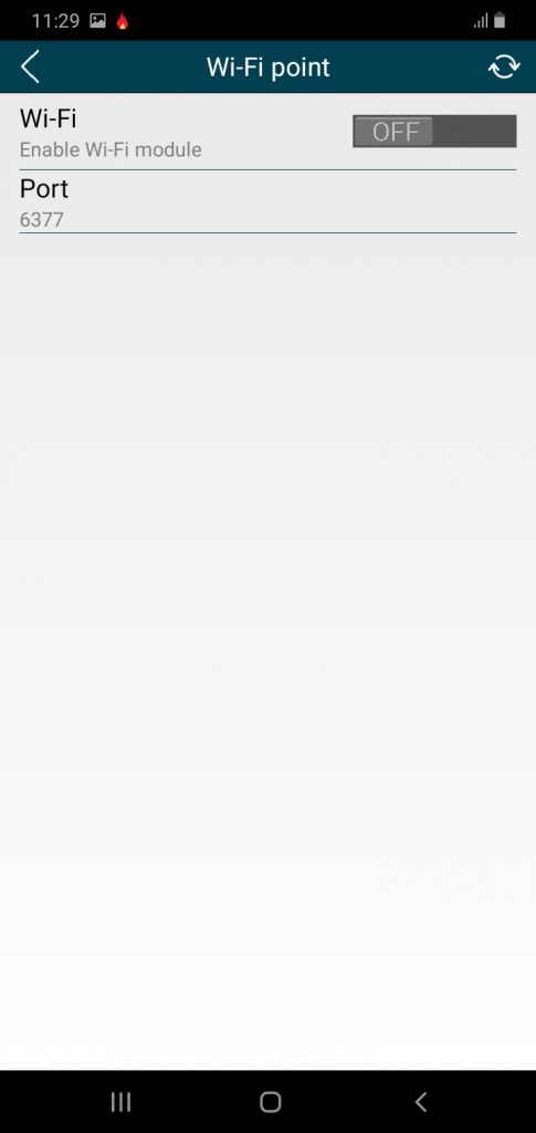
    This would open another page that shows something like this shown below.

    How to Build a Wi-Fi based Smart Farm Monitoring System Project

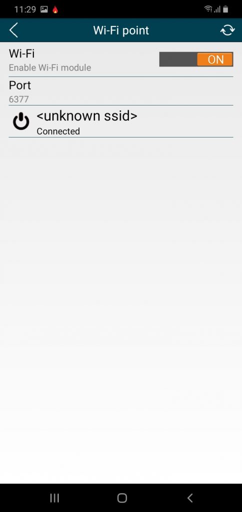
    Turn on your Wi-Fi network (if it is not turned on) and search for the Wi-Fi access point network. This is very important for this How to Build a Wi-Fi based Smart Farm Monitoring System Project to work

    How to Build a Wi-Fi based Smart Farm Monitoring System Project

    You wuld see the network next, connect to it and start viewing and accessing you project remotely via Wi-Fi.

    Smart Wifi control farm

    Check out the video of how the project is working below:

    The working project Video

    Conclusion

    We have done justice to How to Build a Wi-Fi based Smart Farm Monitoring System Project. What do you think? Can you build similar a project design? Let us know in the comment section if you followed this guide to achieve a successful project work. You can contact us and send us pictures and videos of your project design on WhatsApp, Twitter, Telegram, Instagram to and send us pictures or ask questions too.

    Read More

    FAQs on How to Build a Wi-Fi Based Smart Farm Monitoring System Project

    1. What components are needed to build a Wi-Fi-based smart farm monitoring system?

    To build this project, you will typically need an ESP8266 or ESP32 Wi-Fi module, an Arduino board, various sensors (such as soil moisture, temperature, humidity, and light sensors), a relay module to control water pumps or other devices, and a power supply. Additionally, you may need a cloud platform or IoT service to view real-time data remotely.

    2. How does a Wi-Fi-based smart farm monitoring system work?

    The system collects data from sensors placed throughout the farm, such as soil moisture or temperature. The Wi-Fi module (ESP8266 or ESP32) sends this data to an IoT cloud platform where users can monitor the farm conditions remotely through a mobile app or web interface. Automated actions like irrigation can be triggered based on sensor data.

    3. Can this system be used to automate irrigation and other farm tasks?

    Yes, you can integrate relays or automated switches into the system to control irrigation systems, lights, or other equipment. By setting thresholds in the code (e.g., soil moisture levels), the system can automatically turn on or off the irrigation system based on real-time data.

    4. How can I access the farm data remotely?

    You can access real-time farm data through any device connected to the internet, such as a smartphone or computer. The system uses a cloud-based IoT platform like ThingSpeak, Blynk, or custom-built web servers to display the data. You can monitor and control the farm from anywhere with Wi-Fi.

    5. How do I ensure that my Wi-Fi-based farm monitoring system is reliable?

    To ensure reliability, use a stable Wi-Fi connection, secure your system with proper encryption methods, and select sensors that are designed for outdoor use and can withstand farm conditions (e.g., water-resistant sensors). Additionally, regularly maintain the system to check for sensor malfunctions or network interruptions.

  • How to Build an RFID Automated Home Control System

    How to Build an RFID Automated Home Control System

    Imagine walking up to your front door, tapping a small card or key tag, and your lights turn on automatically. Sounds futuristic right?
    Well, with RFID and Arduino, that’s no longer science fiction.

    RFID home automation is one of the simplest and smartest ways to automate access control inside the home. And the best part?
    You can build this system yourself with basic components, an Arduino, and a few lines of code.

    In this guide, I’ll walk you through the process step-by-step, explain how everything works, and help you understand what makes the system reliable and accurate.

    Let’s dive in.

    Importance of RFID in Home Automation

    RFID
    RFID

    An RFID home automation system is a smart control setup that uses Radio Frequency Identification tags to activate devices, unlock doors, or trigger automation actions.

    You simply bring your RFID card close to the sensor…
    …and your system knows exactly what to do.

    Think of it as a digital key that controls specific appliances inside your house.

    Why RFID is Needed in Control Systems

    RFID technology provides several key benefits in home control systems:

    • Access control: RFID tags can be used to grant or deny access to specific areas of your home, such as doors, gates, and security systems.
    • Automation: RFID tags can trigger automated actions, such as turning on lights, adjusting temperature, or activating appliances.
    • Inventory management: RFID can be used to track the location and status of items within your home, such as appliances, tools, or valuables.
    • Personalization: RFID tags can be used to personalize your home environment based on individual preferences and needs.

    Security of RFID Technology

    While RFID technology is generally secure, it is essential to implement appropriate measures to protect against potential vulnerabilities:

    • Encryption: Use encryption algorithms to protect sensitive data transmitted between RFID tags and readers.
    • Authentication: Implement authentication protocols to verify the identity of RFID tags and readers.
    • Physical security: Protect RFID readers and tags from physical tampering or unauthorized access.
    • Regular updates: Keep your RFID system software and firmware up-to-date to address security vulnerabilities.

    ⚙️ How RFID Works in Simple Terms

    RFID is built around two parts:

    🔹 1. The Tag

    This stores a unique ID number and sends it out when scanned.

    🔹 2. The Reader

    This captures the ID and passes it to the Arduino.

    When the Arduino recognizes a stored card ID, it activates whatever you’ve programmed — fan, bulb, security lock, etc.

    It’s like a password you don’t type…
    You just tap.

    Easy.

    Components You Need

    • Power supply of rating 5V, ≥2A or learn how to build your own linear PS here…1pcs
    • Perforated boards(line version)…..2pcs
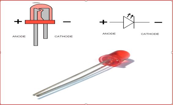
    • Light Emitting Diodes(LEDs)…….5pcs
    • Light Emitting Diode (LEDs)  various colors……………6pcs
    • Current limiting resistor (5 color bands preferably):
      • 10kΩ……5pcs
      • 20 kΩ ……2pcs
      • 56OΩ precision resistor
    • 10KΩ potentiometer (trimmer)
    • Atmega328p-pu Microcontroller…………….2pcs
    • 16 MHz Crystal Oscillator……………………………2pcs
    • Reset Push button………………………..1pcs
    • RFID- RC522 Module……………………………………….1pcs
    • RC522 cards and tags……………………….4pcs
    • 5V 4-channel relay module……………………………1pcs
    • 16×2 Liquid Crystal Display (LCD)…….1pcs
    • LCD connector wires’
    • Header pins
    • Solder………..1pcs
    • Soldering Iron (30W preferably)…..1pcs
    • Solder sucker

    How to Build an RFID Automated Home Control System: The circuit diagram:

    How to Build an RFID Automated Home Control System: the circuit diagram
    RFID for home automation circuit diagram

    We are assuming you already have your 5V, ≥2A power supply. Then solder the circuit diagram as shown above.

    Explanation of the circuit diagram.

    The circuit diagram shown above for how to build an RFID automated home control system consists of the microcontroller unit( MCU), the LCD, RFID module( with tags and rings). It has a 5V linear power supply.

    The Microcontroller Unit (MCU):

    This unit is comprised mainly of;

    • Atmeg168microcontroller
    • 16MHz
      crystal oscillator (Newark part number 16C8140)
    • 22nF
      capacitors
    • A
      10KΩ pull-up resistor
    • A
      reset push button.

    Atmega328p-pu Microcontroller:

    Atmega328P-PU IC used in this project design
    Atmega328P-PU IC used in this project design

    The Atmel 8-bit AVR RISC –based microcontroller combines 32 kB ISP flash memory with read-while-write capabilities, 1 kB EEPROM , 2 kB SRAM, 23 general purpose I/O lines, 32 general purpose working registers , three flexible timer/counters with compare modes, internal and external interrupts, serial programmable USART , a byte-oriented 2-wire serial interface, SPI serial port, 6-channel 10- bit A/D converter (8-channels in TQFP and QFN /MLF packages), programmable watchdog timer with internal oscillator , and five software selectable power saving modes. The device operates between 1.8-5.5 volts. The device achieves throughput approaching 1 MIPS per MHz.

    16 MHz Crystal Oscillator

    The Crystal oscillator
    16Mhz Crystal Oscillator

    More commonly known as a crystal, the crystal oscillator creates an electrical signal with a very accurate frequency. In this case, the frequency is 16 MHz Crystals are not polarized. The schematic symbol is shown in Figure 3.11. The crystal determines the microcontroller’s speed of operation. For example, the microcontroller circuit we’ll be assembling runs at 16 MHz, which means it can execute 16 million processor instructions per second. That doesn’t mean it can execute a line of sketch or a function that rapidly, however, since it takes many processor instructions to interpret a single line of code.

    Reset push button

    Push button used for the RFID access control home automation
    Push button switch

    This is a momentarily switching device that is used to ground the current flowing into the reset pin of the Microcontroller. The reset pin is kept high by a 10k resistor but when the push button is depressed the current flowing into this pin is grounded forcing the microcontroller to restart or reset.

    RFID- RC522 Module

    How to Build an RFID Automated Home Control System: RFID MFRC522
    How to Build an RFID Automated Home Control System: RFID MFRC522

    This is a simple but yet very effective radio frequency module that is used for scanning RFID cards. It uses electromagnetic fields to transfer data between cards and reader. And doesn’t need to be in the line of sight to work, placing the card on the designed area would do the trick. Our module Serial Peripheral Interface (SPI) protocol, making it to have a separate clock and data lines along which we can select our microcontroller we wish to talk to.

    The interface of the Microcontroller to the RFID-RC522 Module is thus:

    • Pin 10 of the Microcontroller is connected to the SDA Pin of RFID-RC522.
    • Pin 13 of the Microcontroller is connected to the SCK Pin of RFID-RC522.
    • Pin 11 of the Microcontroller is connected to the MOSI Pin of RFID-RC522.
    • Pin 12 of the Microcontroller is connected to the MISO Pin of RFID-RC522.
    • Pin NC of the Microcontroller is connected to the IRQ Pin of RFID-RC522.
    • GND Pin of the Microcontroller is connected to the GND Pin of RFID-RC522.
    • Pin 9 of the Microcontroller is connected to the RST Pin of RFID-RC522.
    • 3.3V Pin of the Microcontroller is connected to the 3.3V Pin of RFID-RC522.

    THE RELAY MODULE UNIT

    5V 4-channel relay module
    5V 4-channel relay module

    This consist of a LOW Level 5V 4-channel relay interface board, and each channel needs a 15-20mA driver current. It can be used to control various appliances and equipment with large current. It is equipped with high-current relays that work under AC250V 10A or DC30V 10A. It has a standard interface that can be controlled directly by microcontroller. This module is optically isolated from high voltage side for safety requirement and also prevent ground loop when interface to microcontroller.

    • Relay Maximum output: DC 30V/10A, AC 250V/10A.
    • • 4 Channel Relay Module with Opto-coupler. LOW Level Trigger expansion board, which is compatible with Arduino control board.
    • • Standard interface that can be controlled directly by microcontroller (8051, AVR, *PIC, DSP, ARM, ARM, MSP430, TTL logic).
    • • Relay of high quality low noise relays SPDT. A common terminal, a normally open, one normally closed terminal.
    • • Opto-Coupler isolation, for high voltage safety and prevent ground loop with microcontroller.

    LCD Connector Wires and header socket pins:

    LCD connector wire and socket pins
    LCD connector wire and socket pins

    This is a 16 in-line wires configured according to the number of the LCD inputs and output pins.

    It reads and writes data communication from and to the MCU. In handling the LCD connector wires, care must be taken to ensure that each of the connector is matched according to its assigned pin hole.

    The header socket pins is a male-female wire socket to the LCD connector wire. It makes it very simple to connect to the LCD and the MCU

    The Schematic Diagram

    circuit diagram for home automation of control of Four
home appliances
    circuit diagram for home automation of control of Four home appliances

    Techniques

    Thinning

    Thinning involves the smooth scrapping of terminal components either by knife or sand paper before soldering.

    Assembling of Components

    The number of components determined the size of the VERO board used and in dimensioning the size of board, allowance is given for the arrangement if the need arises.

    • Begin by placing the components that require a specific location first.
    • Leave at least 10 centimeters between components and the VERO Board edge.
    • Attempt to space out your components evenly horizontally and vertically and orient the circuit components the same direction whenever possible for consistency.
    • Insure that the orientation of polarized parts is the same.
    • Avoid placing your components at angles other than 0 or 90 degrees
    • When it is necessary to have components on both sides, keep sensitive, heavy, or through hole components on the primary side. Also, any components that need special attention should be kept on the primary side of the printed circuit board as well.
    • When deciding where to place components, trace lengths were minimized

    Casing

    In the selection of a suitable casing for the RFID  controlled home appliances system, the components on the board will be taken into consideration; vents will be created around the cover. For cooling of the device and holes for the transformer and the voltage regulators.

    Having completed mounting, soldering and interfacing all the components, this is followed by checking and confirming that the system is performing as per specification. It is necessary to carry out the short circuit, open circuit, load and no- load tests to confirm the integrity of the MCU, and RFID control unit. Before carrying out these tests we made sure that all connections to a power source are isolated.

    To determine the effectiveness of the project, How to Build an RFID Automated Home Control System; two major tests namely Load and No-load tests were carried out (by connecting a LED to the output of the Microcontroller unit (MCU)).

    These steps are very necessary for the project: How to Build an RFID Automated Home Control System

    The Source-code

    Since each tag and card has a unique ID, it is very important to know their identities and map their IDs to a specific set of functions. To do this on the Arduino platform, go to the Arduino IDE, open it and install the following MFRC RFID library.

    After successful installation, open the IDE and click on File, scroll down to Examples and select MFRC and under the available options, open the ReadNUID and you will see something like this:

    how to design an RFID smart hoe control system
    The RFID read tag sketch

    Verify your connection and click on verify on the IDE and after verification, upload the sketch. Open the Serial monitor, ensure that your baud rate is at 9600 and bring your tag closer to the MFRC reader to see each ID as shown on the Serial monitor. Copy the content.substring shown on the screen. Keep this safe and use it in the sketch below. By replacing ours with your very own content.substring ID codes.

    To control only one socket switch and one AC light bulb; the following source code is used.

    /*  Program  to use RFID CARDS TO CONTROL 
     *   TWO HOME APPLIANCES
     */
    
    //include the LCD lib
    #include <LiquidCrystal.h>
    
     //include the RFID libs
    #include <SPI.h>
    #include <MFRC522.h>
    
     //declear the reset and SDA pins of RFID
    #define SS_PIN 10
    #define RST_PIN 9
    MFRC522 mfrc522(SS_PIN, RST_PIN);   // Create MFRC522 instance.
    //state the output pins for appliaces
    #define LED1 A1
    #define LED2 A2
    int ledState1 = 0;
    int ledState2 = 0;
    LiquidCrystal lcd(7, 6, 5, 4, 3, 2); 
     
    void setup() 
    {
       // Initiate a serial communication
      Serial.begin(9600);
      // Initiate  SPI bus  
      SPI.begin();
      // Initiate MFRC522      
      mfrc522.PCD_Init();
      //begin the LCD
      lcd.begin(16, 2);   
      Serial.println("Approximate your card to the reader...");
      Serial.println();
      pinMode(LED1, OUTPUT);
      pinMode(LED2, OUTPUT);
    //display a welcome note
      lcd.setCursor(0, 0);
      lcd.print("WELCOME DAVID");
      delay(2000);
      lcd.setCursor(0, 0);
      lcd.print("RFID CONTROLLED ");
      lcd.setCursor(0, 1);
      lcd.print("HOME APPLIANCES");
      delay(3500);
      lcd.clear();
      
    }
    void ledOne() 
    {
       // Look for new cards
      if ( ! mfrc522.PICC_IsNewCardPresent()) 
      {
        return;
      }
      // Select one of the cards
      if ( ! mfrc522.PICC_ReadCardSerial()) 
      {
        return;
      }
      //Show UID on serial monitor
      Serial.print("UID tag :");
      String content= "";
      byte letter;
      for (byte i = 0; i < mfrc522.uid.size; i++) 
      {
         Serial.print(mfrc522.uid.uidByte[i] < 0x10 ? " 0" : " ");
         Serial.print(mfrc522.uid.uidByte[i], HEX);
         content.concat(String(mfrc522.uid.uidByte[i] < 0x10 ? " 0" : " "));
         content.concat(String(mfrc522.uid.uidByte[i], HEX));
      }
      Serial.println();
      Serial.print("Message : ");
      content.toUpperCase();
      if (content.substring(1) == "0A DB D9 06") //change here the UID of the card/cards that you want to give access
      {
            // if the LED is off turn it on and vice-versa:
        if (ledState1 == 0) {
          ledState1 = 255;
          lcd.setCursor(2, 1);
          lcd.print("ON ");
        } else {
          ledState1 = 0;
          lcd.setCursor(2, 1);
          lcd.print("OFF ");
        }
    
        // set the LED with the ledState of the variable:
        analogWrite(LED1, ledState1);
      }
    delay(500);
    }
    void ledTwo() {
       // Look for new cards
      if ( ! mfrc522.PICC_IsNewCardPresent()) 
      {
        return;
      }
      // Select one of the cards
      if ( ! mfrc522.PICC_ReadCardSerial()) 
      {
        return;
      }
      //Show UID on serial monitor
      Serial.print("UID tag :");
      String content= "";
      byte letter;
      for (byte i = 0; i < mfrc522.uid.size; i++) 
      {
         Serial.print(mfrc522.uid.uidByte[i] < 0x10 ? " 0" : " ");
         Serial.print(mfrc522.uid.uidByte[i], HEX);
         content.concat(String(mfrc522.uid.uidByte[i] < 0x10 ? " 0" : " "));
         content.concat(String(mfrc522.uid.uidByte[i], HEX));
      }
      Serial.println();
      Serial.print("Message : ");
      content.toUpperCase();
      if (content.substring(1) == "35 F7 F0 D1") //change here the UID of the card/cards that you want to give access
      {
           // if the LED is off turn it on and vice-versa:
        if (ledState2 == 0) {
          ledState2 = 255;
          lcd.setCursor(12, 1);
          lcd.print("ON ");
        } else {
          ledState2 = 0;
          lcd.setCursor(12, 1);
          lcd.print("OFF ");
        }
    
        // set the LED with the ledState of the variable:
        analogWrite(LED2, ledState2);
      }
       delay(500); 
    }
    
    void loop()
    {
      lcd.setCursor(0, 0);
    lcd.print("Light:   Socket:");
    ledOne();
    ledTwo();
    }


    Explantion of Code

    Although the sketch contains comment lines to explain some of the sketch… But from the beginning line of code; we imported libraries for the Serial peripheral interface SPI, which is necessary since it is the type of communication the RFID RC522 uses. Then the lib for the LCD and the MFRC522 lib were also imported at line 6 through line 10.

    At line 13 and 14, we define where connected out Slave Select pin and our Reset pin(which is pin 10 and 9 respectively). After creating the RC522 instance, we declare which of the MCU pins we are connecting the AC light bulb and the socket (line 17 and 18).

    Since we are using an Active LOW relay module unit, We declared and put the relay state to be ON, at line 19 and 20. Next we declared where we are connecting the LCD data signal pins. Since we are using 4-bits, not 8-bits. We state it there.

    In the void setup function, we kick started the SPI protocol and initialized the type of RFID at line 29 and 30 respectively. The same with the LCD at line 32 as we make our two outputs known.

    After this, we print a welcome message, Since this project was inspired by Mr. David from Landmark varsity; we display his name. We would want the message displayed to stay for a while before disappearing; hence, we put a delay of 3.5 seconds.  And we cleared the LCD to received more instructions from the MCU after that.

    We created two functions: ledOne() and ledTwo() (at line 49 and 93 respectively) to handle the states of the AC light bulb and the Socket load point. Basically what these functions does is to check if there is the presence of the ring or tag that has been mapped to them and if there is; it would change the state on the MCU pins stated earlier from 0 to 255 and if it notice the tag or ring presence again it would change to the previous state and vice versa. This will create a kind of changeState effect any time it senses the RFID tag or card mapped to it.

    The youtube video below shows How to Build an RFID Automated Home Control System. Click below to watch the video.

    If you want to learn how to build an RFID Automated Home Control System that would control two AC light bulbs and two sockets switches, we use the following circuit diagram:

    The Final Sketch below was used

    /*  Program  to use RFID CARDS TO CONTROL 
     *   FOUR HOME APPLIANCES
     */
    
    //include the RFID libs
    #include <SPI.h>
    #include <MFRC522.h>
    
    //include the LCD lib
    #include <LiquidCrystal.h>
    
     //declear the reset and SDA pins of RFID
    #define SS_PIN 10
    #define RST_PIN 9
    // Create MFRC522 instance.
    MFRC522 mfrc522(SS_PIN, RST_PIN);   // Create MFRC522 instance.
    //declear what LCD pins u are sending data
    LiquidCrystal lcd(8, 7, 6, 4, 3, 2);
    
    #define BULB1 A1
    #define BULB2 A2
    #define SOCKET1 A3
    #define SOCKET2 A4
    int bulbState1 = 0;
    int bulbState2 = 0;
    int socketState1 = 0;
    int socketState2 = 0;
    
    void setup() {
     pinMode(BULB1, OUTPUT);
     pinMode(BULB2, OUTPUT);
     pinMode(SOCKET1, OUTPUT);
     pinMode(SOCKET2, OUTPUT);
     //turn all the relays off
     digitalWrite(BULB1, 255);
     digitalWrite(BULB2, 255);
     digitalWrite(SOCKET1, 255);
     digitalWrite(SOCKET2, 255);
       // Initiate a serial communication
      Serial.begin(9600);
      // Initiate  SPI bus  
      SPI.begin();
      // Initiate MFRC522      
      mfrc522.PCD_Init();
      //begin the LCD
      lcd.begin(16, 2); 
    //display a welcome note
      lcd.setCursor(0, 0);
      lcd.print("WELCOME UCHE");
      delay(2000);
      lcd.setCursor(0, 0);
      lcd.print("RFID CONTROLLED ");
      lcd.setCursor(0, 1);
      lcd.print("HOME APPLIANCES");
      delay(3500);
      lcd.clear();
    }
    
      void bulbOne() {
         // Look for new cards
      if ( ! mfrc522.PICC_IsNewCardPresent()) 
      {
        return;
      }
      // Select one of the cards
      if ( ! mfrc522.PICC_ReadCardSerial()) 
      {
        return;
      }
      //Show UID on serial monitor
      Serial.print("UID tag :");
      String content= "";
      byte letter;
      for (byte i = 0; i < mfrc522.uid.size; i++) 
      {
         Serial.print(mfrc522.uid.uidByte[i] < 0x10 ? " 0" : " ");
         Serial.print(mfrc522.uid.uidByte[i], HEX);
         content.concat(String(mfrc522.uid.uidByte[i] < 0x10 ? " 0" : " "));
         content.concat(String(mfrc522.uid.uidByte[i], HEX));
      }
      Serial.println();
      Serial.print("Message : ");
      content.toUpperCase();
      //this is where u put the UID of the card that you want to give access
      if (content.substring(1) == "55 E5 07 88") 
     // previousMillis = currentMillis;
      { if (bulbState1 == 0) {
          bulbState1 = 255;
          lcd.setCursor(0, 1);
          lcd.print("OFF ");
          } 
       else {
          bulbState1 = 0;
          lcd.setCursor(0, 1);
          lcd.print("ON ");
          }
        // set the bulb with the bulbState of the variable:
        analogWrite(BULB1, bulbState1);
      }
      delay(150);
    }
    
    void bulbTwo() {
         // Look for new cards
      if ( ! mfrc522.PICC_IsNewCardPresent()) 
      {
        return;
      }
      // Select one of the cards
      if ( ! mfrc522.PICC_ReadCardSerial()) 
      {
        return;
      }
      //Show UID on serial monitor
      Serial.print("UID tag :");
      String content= "";
      byte letter;
      for (byte i = 0; i < mfrc522.uid.size; i++) 
      {
         Serial.print(mfrc522.uid.uidByte[i] < 0x10 ? " 0" : " ");
         Serial.print(mfrc522.uid.uidByte[i], HEX);
         content.concat(String(mfrc522.uid.uidByte[i] < 0x10 ? " 0" : " "));
         content.concat(String(mfrc522.uid.uidByte[i], HEX));
      }
      Serial.println();
      Serial.print("Message : ");
      content.toUpperCase();
      if (content.substring(1) == "22 80 F5 BA") 
       {
        if (bulbState2 == 0) {
          bulbState2 = 255;
          lcd.setCursor(4, 1);
          lcd.print("OFF ");
          }
      else {
          bulbState2 = 0;
          lcd.setCursor(4, 1);
          lcd.print("ON ");
         }
        analogWrite(BULB2, bulbState2);
      }
       delay(150); 
    }
    
    void socketOne() {
         // Look for new cards
      if ( ! mfrc522.PICC_IsNewCardPresent()) 
      {
        return;
      }
      // Select one of the cards
      if ( ! mfrc522.PICC_ReadCardSerial()) 
      {
        return;
      }
      //Show UID on serial monitor
      Serial.print("UID tag :");
      String content= "";
      byte letter;
      for (byte i = 0; i < mfrc522.uid.size; i++) 
      {
         Serial.print(mfrc522.uid.uidByte[i] < 0x10 ? " 0" : " ");
         Serial.print(mfrc522.uid.uidByte[i], HEX);
         content.concat(String(mfrc522.uid.uidByte[i] < 0x10 ? " 0" : " "));
         content.concat(String(mfrc522.uid.uidByte[i], HEX));
      }
      Serial.println();
      Serial.print("Message : ");
      content.toUpperCase();
      if (content.substring(1) == "F3 0A 50 2D") 
      {
        if (socketState1 == 0) {
          socketState1 = 255;
          lcd.setCursor(9, 1);
          lcd.print("OFF ");
          } 
        else {
          socketState1 = 0;
          lcd.setCursor(9, 1);
          lcd.print("ON ");
          }
        analogWrite(SOCKET1, socketState1);
      }
       delay(150); 
    }
    
    void socketTwo() {
       // Look for new cards
      if ( ! mfrc522.PICC_IsNewCardPresent()) 
      {
        return;
      }
      // Select one of the cards
      if ( ! mfrc522.PICC_ReadCardSerial()) 
      {
        return;
      }
      //Show UID on serial monitor
      Serial.print("UID tag :");
      String content= "";
      byte letter;
      for (byte i = 0; i < mfrc522.uid.size; i++) 
      {
         Serial.print(mfrc522.uid.uidByte[i] < 0x10 ? " 0" : " ");
         Serial.print(mfrc522.uid.uidByte[i], HEX);
         content.concat(String(mfrc522.uid.uidByte[i] < 0x10 ? " 0" : " "));
         content.concat(String(mfrc522.uid.uidByte[i], HEX));
      }
      Serial.println();
      Serial.print("Message : ");
      content.toUpperCase();
      if (content.substring(1) == "8B 33 E9 A9")
      {
        if (socketState2 == 0) {
          socketState2 = 255;
          lcd.setCursor(13, 1);
          lcd.print("OFF ");
          }
      else {
          socketState2 = 0;
          lcd.setCursor(13, 1);
          lcd.print("ON ");
          }
      analogWrite(SOCKET2, socketState2);
      }
       delay(150); 
    }
    
    void loop() {
      lcd.setCursor(0, 0);
      lcd.print("L1: L2:  S1: S2:");
      bulbOne();
      bulbTwo();
      socketOne();
      socketTwo();


    Conclusion

    We hope this helps and now you know how to build an RFID automated home control system. What do you think? Can you build similar a project design? Let us know in the comment section if you followed this guide to achieve a successful project. You can contact us and send us pictures and videos of your project design on WhatsApp, Twitter, Telegram, Instagram to and send us pictures or ask questions too.

    Read More

    Feel free to leave us a comment at any time. Thanks.

    Frequently Asked Questions

    1. What type of RFID tags should I use for my home automation system?
      • The choice of RFID tags depends on your specific requirements, such as read range, durability, and security. Common types of RFID tags include passive tags, active tags, and near-field communication (NFC) tags.
    2. How can I integrate RFID into my existing home automation system?
      • You can integrate RFID into your existing home automation system by using RFID readers and controllers that are compatible with your system’s protocol.
    3. Can RFID technology be used for home security?
      • Yes, RFID technology can be used for home security applications, such as access control, intrusion detection, and perimeter security.
    4. Are RFID tags expensive?
      • The cost of RFID tags varies depending on the type of tag, read range, and quantity. However, RFID technology has become more affordable in recent years.
    5. What are the potential challenges of using RFID technology in home automation?
      • Some potential challenges include interference from other electronic devices, battery life issues for active tags, and the need for proper installation and configuration.
  • Solar Inverters Energy Solution – Installation and maintenance for cleaner Energy

    Solar Inverters Energy Solution – Installation and maintenance for cleaner Energy

    Introduction

    Everywhere you look today, the world is talking about cleaner electricity, renewable energy and sustainable living. Solar energy is no longer a futuristic idea. It is a reality we can install in our homes, offices, farms and industries.

    And at the heart of every reliable solar system is one key device – the solar inverter.

    The slide video

    Without the inverter, your panels are basically silent collectors of sunlight.
    With the inverter, they become your personal power station.

    In this guide, we’ll break down what solar inverters really do, how to install them safely, and how to maintain them so they last long, save money and support a cleaner environment.

    Let’s get into it.

    How to Get Solar Inverter Energy Solution

    solar inverter energy solution
    A neatly installed energy solution

    The very first step to get a solar inverter energy solution from us at Smartech is to contact us on any of our handles. They are listed below

    You can reach out to us on any of these social media handles to reach us and tell us the loads or what type of facility you want to power. We will do an evaluation of the cost for you and send you a proper quote.

    solar inverter solution
    mounted PV panels

    Most of the time we work with clients on how to make the best of their budget for the installation of this solution. By talking to us, we can arrive at what your money can get you and how you can make the best out of it.

    Solar inverter batteries on rack
    Solar inverter batteries on rack

    Conclusion

    Solar inverters are the backbone of every successful solar energy system. Installing and maintaining them correctly ensures long-term power stability, financial savings, and environmental impact.

    The future belongs to clean energy…
    and solar inverters are leading that future.

    If you want energy independence, lower electricity bills and a greener home, then investing in a solar inverter system is one of the smartest decisions you can make.
    Let us know what you think for this offer by reaching to us on our socials.

    Random FAQs

    1. Can I install a solar inverter myself?
    Only if trained. Otherwise, always use a certified installer.

    2. Why is ventilation important for inverters?
    Heat reduces lifespan and efficiency.

    3. How often should I service a solar inverter?
    At least once every 6–12 months.

    4. Can a solar inverter power AC appliances?
    Yes, as long as the rating matches the load.

    5. Does weather affect inverter performance?
    Not directly, but heat and humidity can.

    Read More

  • How to Install CCTV Surveillance Cameras with Remote Viewing

    How to Install CCTV Surveillance Cameras with Remote Viewing

    Introduction

    Security has become personal. We all want to protect our homes, offices, shops, warehouses and properties — even when we’re not physically there. That’s where CCTV surveillance cameras come in.

    But installing CCTV cameras is only half of the journey.
    Being able to watch your cameras on your phone from anywhere in the world is the real win.

    In this guide, I’ll break everything down in a simple, friendly way — so that you understand what you’re doing, why you’re doing it, and how everything connects together smoothly.

    No complicated jargon.
    No schematic diagrams.
    Just real-world installation steps you can follow.

    Let’s dive in.

    Types of CCTV Systems You Can Install

    Choosing the right system makes installation easier.

    1. Wired CCTV System

    Uses coaxial/ethernet cables.
    Very stable and reliable.

    2. Wireless CCTV System

    Uses Wi-Fi signals.
    Fast setup. No long cables.

    3. IP Camera System

    Runs fully on network.
    Best video quality.

    4. Hybrid Camera System

    Mix of old and new tech.

    The right choice depends on environment, budget, and coverage area.

    Materials Needs

    • 8-Channel DVR
    • 2MP bullet Camera
    • VGA to AV Converter
    • 12V Power Supply Adapter
    • HDMI cable
    • BNC plugs
    • DC Power Jack
    • RG59 Coaxial Cable with power

    If you prepare well,
    installation becomes smooth.

    Steps To Install CCTV surveillance Cameras with Remote Viewing

    Step 1: Prep the Digital Recorder (DVR)

    Before we start off; it is very important you set up the DVR and turn it on. Connect your mouse and your DVR power jack to the 12V supply output of the 12V adapter. Connect the VGA cable from the DVR to the monitor or TV using HDMI or VGA to AV converter. Allow it to boot, and watch its progress on a monitor or TV if you are using a VGA to AV converter.

    Step 2: Prep the Power Cable

    how to install CCTV surveillance cameras with a remote viewing
    RG59 coaxial cable with power at point of mounting camera

    Then, there is little or no need to make any change as regards to where the cameras would be positioned. Otherwise, it would be good to choose positions where the cams would be somewhat hidden and have little or no blind spot views. So, if given the option for a surface wiring, identify these positions.

    how to install CCTV surveillance cameras with a remote viewing
    Crimped out RG59 wires with power

    Use a wire crimping tool and peel off the wires as shown in the picture above. This is useful to connect the 12V power to the CCTV male power plug. This is done in a way that the positive (usually red color) +12V wire is connected to the point marked (+) whereas the negative wire (black colored) is connected to the port marked (-).

    CCTV male power plug

    Step 3: Prep the RG59 Coaxial cable

    open the BNC connector
    first move

    Take the BNC connect and unscrew the female-female couple. Push the end of the cable into the F- connector so the connector tube goes between the foil and the outer housing of the cable.

    the next move
    next move

    push the end until the white insulator is flush with the bottom of the connector. Use anything to expose 1/8 inch of the braid and foil by pinching and pulling off a piece of the out jacket. DO NOT ALLOW ANY OF THE COPPER SHIELDING TO TOUCH THE CENTER OF THE CONDUCTOR

    the last move
    the last move

    Slide the crimp ring inside over the bottom of the connector and screw on tightly. Using a crimping tool, pinch pinch the shield to secure a strong housing. Test the cable using a Cable tester after this.

    Step 4: Prep the CCTV Cameras

    After you are done with the RG59 wiring; bring out the cameras from their packs.

    how to install CCTV surveillance cameras with a remote viewing
    We used CP plus for this tutorial.

    This blog post used CCTV Bullet cameras from CP plus industries. You can read more about their specifications at their product web page.

    how to install CCTV surveillance cameras with a remote viewing
    A dome CCTV type camera
    Setting the CCTV Camera
    adjust the CCTV camera according to where you want

    It is important to note that surveillance cameras with higher megapixel(MP) ratings tend to have better image capture and streaming than the one with lower MP ratings. For example this tutorial was made with cameras with 1.3MP and 2MP resolution qualities.

    Alternatively, you have to choose cameras with Night vision attributes so that you can also watch your surveillance at night. And between HD720 and HD1080, always go for the latter.

    Smartech CCTV

    Remove the cameras from their packs and begin to unscrew them carefully. If you are planning to survey the outside surroundings of the place you are installing the CCTV surveillance; it is recommended to use the Bullet (or turret) type of camera for the outdoors and the dome type for indoor surveillance.

    Smartech CCTV

    Each of the cameras comes with two plug and set connectors(other manufacturers might add a picture mode button, like in the case of CP Plus). This is where you would connect you BNC from your RG59 coaxial and your power.

    Smartech CCTV

    These cameras run on 12V and about 250mA-350mA current rating. Ensure you have a stable power supply unit for this or get a 16-channel power supply used to power CCTV cams. This is what we used for this how to install CCTV surveillance cameras with a remote viewing wiki.

    Step 5: Drill Holes For Wall Pegs

    Smartech CCTV
    dripping holes for mount pegs

    Remove the mount (drill) template for any of the cameras you wish to install and mark out the positions to drill for your pegs. There is need to go to each spot and measure out the exact spot and take note of this. Using a drilling machine with a good torque. Make holes and insert the wall pegs into these holes. These would serve as fastening points for the CCTV cameras.

    how to install CCTV cameras
    put the pegs in the holes drilled

    Use your hand drill machine and drill these holes into the wall. Insert the pegs and then ensure that they are firm.

    how to install CCTV Cameras

    Place the base of your camera and use the screw to hold it firm.

    Installing the Hard Disk (HDD) for Recording/Playback

    Turn off the DVR for this process. And open the DVR by unscrewing the safety screws that held the cover.

    how to open a DVR set
    unscrew the screw holding the casing of the DVR
    Smartech CCTV
    The inside of the DVR

    Install the HDD by connecting the HDD connectors to its appropriate sockets and hold the HDD in place by screwing from below.

    Go back to your screen on the monitor and start the recording by right clicking on the mouse and selecting “start recording“.

    You should see the channels of cams connected showing together. Select any one and display its full view.

    how to install CCTV surveillance cameras with a remote viewing
    how to install CCTV surveillance cameras with a remote viewing
    The various cameras showing in their chambers

    Configuring CCTV Camera For Remote Viewing

    To view the surveillance view remotely, you would need a 4G router.  You can get a TP-Link 4G router just like the one shown below:

    how to install CCTV surveillance cameras with a remote viewing
    the tp-link router pack

    Open your router pack and bring out the router.  Push the SIM into its slot and power it up.

    the tp-link back

    The rest of the steps is quite easy and straightforward. Just follow the installation guide on the pamphlet manual to complete the rest of the procedure that is needed.

    The XMEye Mobile App

    Next, download the XMEye app either from the Playstore or iTunes store and create a cloud-based account. Link the DVR to that router and connect it.

    how to install CCTV surveillance cameras with a remote viewing
    Create a cloud based account and log in
    XMEye CCTV remote view
    online remote view
    how to install CCTV surveillance cameras with a remote viewing

    Getting the XMEye app to get started usually take some time. You have to wait for it to buffer and finish loading and you can enjoy your remote viewing.

    The slide YouTube vide

    Conclusion

    Getting started with CCTV cameras and installation in this how to install CCTV surveillance cameras with a remote viewing guide. Let us know in the comment section if you followed this guide to achieve a successful remote surveillance for your home or office security monitoring. You can contact us on WhatsApp, Twitter, Telegram, Instagram to and send us pictures or ask questions too.

    Read More

    FAQs

    1. What type of cameras should I choose for my CCTV system?

    • The choice of cameras depends on your specific needs. Dome cameras are discreet and ideal for indoor use, while bullet cameras are more visible and suitable for outdoor areas. PTZ cameras offer the ability to pan, tilt, and zoom, making them versatile for large areas.

    2. Can I use wireless cameras instead of wired ones?

    • Yes, wireless cameras are an option if you prefer not to run cables. However, they require a stable Wi-Fi connection and may need to be placed within range of your router. Keep in mind that wireless cameras still require power, so consider how you’ll provide it.

    3. How much storage do I need for my CCTV system?

    • The amount of storage depends on the number of cameras, resolution, and recording settings. A 1TB hard drive can store several weeks of footage from multiple cameras at standard resolution. Consider larger drives if you need longer retention periods or higher resolution.

    4. What should I do if I can’t view my cameras remotely?

    • If you’re having trouble viewing your cameras remotely, ensure that your DVR/NVR is connected to the internet and that remote access is enabled. Double-check the network settings and make sure your mobile app or software is configured correctly. Rebooting your router and DVR/NVR can also help resolve connectivity issues.

    5. Is it legal to install CCTV cameras on my property?

    • Yes, it is legal to install CCTV cameras on your property for security purposes. However, you must respect the privacy of others and avoid recording areas that are not part of your property, such as public streets or neighboring properties. Be sure to check local laws and regulations regarding CCTV use.
  • How to Build Linear Power Supply Unit

    How to Build Linear Power Supply Unit

    Today, we are constructing a traditional power supply unit with a maximum output of 5V and 1A (or 3A with an LM323T DC supply). which we may subsequently utilize to power any of our microelectronics projects that require that level of DC power. Basic components of electronics engineering are required. You will learn how to construct a 5V linear power supply unit that can power your prototype electronics if you study this tutorial through to the finish.

    What is a Linear Power Supply?

    A linear power supply is a type of power supply that converts an AC input voltage to a regulated DC output voltage. The key components of a linear power supply include a transformer, rectifier, filter capacitor, and a voltage regulator. These components work together to ensure that the output voltage is stable and free from noise, even under varying load conditions.

    Building a linear power supply is a rewarding project for electronics enthusiasts and professionals alike. Unlike switching power supplies, which can generate electrical noise, a linear power supply provides a clean and stable DC output, making it ideal for sensitive electronics applications. In this guide, we’ll go through the process of designing and constructing a 5V linear power supply.

    Materials/Components

    • 2A AC socket plug,
    • 2A A.C switch (Rocker Switch),
    • A 12V-0-12V transformer
    • 9 meters of calculated millimeter diameter conduction wire
    • (50mA- 2A) connector wires (generic jumper wires male or female)
    • Full wave rectifying bridge
    • 2 calculated capacitors values: 100f and 0.1f.
    • L7805CV 5V voltage regulator IC
    • 10K and 20k current-limiting resistors
    • connector clips
    • connector screws,
    • insulating caps
    • 2 Perforated boards (line version),
    • 2 Light Emitting Diodes (LEDs).

    How to Build Linear Power Supply Unit: 12V-0-12V Step-down AC Voltage Transformer

    How to build Linear power supply unit
    A typical 12V-0-12V transformer used here

    In order to convert 220V – 240V AC to a 5V DC, first we need a step-down transformer to reduce such high voltage. Here we have used 12V-0-12V 1A step-down transformer, which convert 220V AC to 12V AC on single coil and 24V on two coils. In a transformer component, there are primary and secondary coils which step up or step down the voltage according to the number of turns in the each of the coils.

    Selection of a proper transformer is very important. Current rating depends upon the Current requirement of Load circuit. This transformer choice was made because the voltage rating of the transformer should be more than the required voltage of the output. Since we needed  a 5V DC output supply,  and the transformer with a rating of 12V is ideal.  Because during voltage regulation, our voltage regulator IC need more voltage to operate. For example, L7805 needs at least need 2V more that’s 7V to provide a 5V voltage.

    1mm Diameter Conduction Wire

    The length of this type of conduction wires used here was determined by how long the sources of the power supplies are from the device. Choice made was based on calculation of conduction wire diameter; a 1mm diameter wire will give the material increase in resistance and less current capacity and decrease in heat loss. Hence, it will avoid quick burn out. From laws of Resistance;

    How to build Linear power supply unit
    Resistance equation

    This means that the diameter of a cross-sectional area of the wire affects the current carrying capacity of the wire. The conduction wires here are 10A, 220/240 VAC.

    Jumper Wires

    How to build Linear power supply unit

    This electronics component was needed to conduct D.C voltage in the power supply unit (and other units). It helped us to avoid short circuits and open circuits in this/these unit(s). It also distributes suitable voltages to each component we used during the design.

    Full Wave Bridge Rectifier VS048

    How to build Linear power supply unit
    VS048 bridge rectifier

    Rectification is the process of removing the negative part of the Alternate Current (AC), hence producing the partial DC. This can be achieved by using 4 power diodes. Diodes only allow current to flow in one direction (not completely true, because of minority carriers’ movement, avalanche breakdown and Peak Inverse voltage). In designing the power supply unit, two diodes D2 & D3 are needed in the first half cycle of AC, and are hence placed in the forward biased configuration.  Another two power diodes, D1 and D4 are placed in the reversed biased configuration, and in the second half cycle (negative half) Diode D1 and D4 are forward biased and D2 and D3 are reversed biased. This Combination converts the negative half cycle into positive.  Alternatively, we choose a full wave bridge rectifier component VS048 which consist that combination of 4 diodes internally.

    A diode bridge makes use of four diodes in a bridge arrangement to attain full-wave rectification. This is more commonly known as a bridge rectifier. Its output is rectified DC from an AC source and the polarity is the same regardless of the polarity of the AC input. The resulting output waveform is not true DC, it contains a ripple. When used in power supplies to rectify the incoming AC the output waveform must be handled by the rest of the power supply circuitry to reduce its ripple thus making a clean DC output. Another application would be reverse polarity protection in the input of a battery circuit to make sure no damage would occur if a battery was inserted into a device with the wrong polarity. And we do not want this in this How to build Linear power supply unit tutorial guide.

    Filter Capacitors

    filter capacitor
    1000uF 50V filter capacitor

    The output after the Rectification is not a proper DC, it is oscillation output and has a very high ripple factor. We don’t need that pulsating output, for this we use Capacitor. Capacitor charge till the waveform goes to its peak and discharge into Load circuit when waveform goes low. So when output is going low, capacitor maintains the proper voltage supply into the Load circuit, hence creating the DC. We thus calculated the value of the filter capacitor using the following formula:

    C=(I ×t)/V = Q/V 
    C= capacitance to be calculated
    I= Max output current (which is about 1000mA)
    t = 10ms,


    We will get wave of 100Hz frequency after converting 50Hz AC into DC, through full wave bridge rectifier. As the negative part of the pulse is converted into positive, one pulse will be counted two.

    So the Time period, t, will be 1/100 = 0.01 Second = 10ms
     V = Peak voltage - voltage  given to voltage regulator.
     V= 5+2=7 (+2 more than rated means). 
     Now, if 12-0-12 is the RMS value of transformer so peak voltage is:
    Vrms × 1.414 = 12× 1.414= 16.968V
    1.4V will be dropped on 2 diodes (0.7V per diode) as 2 diodes will be forward biased for half wave.
     Hence, 16.968V– 1.4V = 15.568V
     When capacitor discharges into load circuit, it must provide 7v to voltage regulator to work so finally V is:
     V = 15.568 – 7= 8.568v
     But since,  C=(I×t)/V 
     C=(1000mA×10ms)/8.568v=(1×0.01)/8.568=1167µF≃1000µF 
    

    Voltage Regulators or Stabilizers

    How to build Linear power supply unit
    LM7805 voltage regulator

    The voltage regulator IC, L805CV is used to provide a regulated 5V DC output. Input voltage should be 2 volts more than the rated output voltage for proper working of Integrated Circuit (IC), that means, for 5V DC output, at least 7v is needed (in which case, 16V was fed into it) Although most voltage regulator Integrated Circuit, can operate in input voltage range of 7-20V. Voltage regulators have all the circuitry inside it to provide a proper regulated DC. A capacitor of 0.01uF was connected to the output of the  IC LM7805 to eliminate the noise, produced by transient changes in voltage.

    Resistors

    75kohms resistor
    75kΩ five band resistor

    Resistors are electronics components that introduce some amount of resistance into a circuit. The values of the resistors incorporated in this project design for current limiting purposes ranged from 47Ω to 100KΩ. The resistors main functions here are used to protect current sensitive components like LEDs and to stepdown voltages to appropriate values.

    Light Emitting Diode (LED)

    LED and its schematic symbol

    Also called Light Emitting Diodes, LEDs are diodes that basically convert electrical energy to light energy. The LEDs to be used here are Red and Green to show indication of supply either A.C or D.C. The Green LED would indicate that power has been connected to the Power Supply unit while the Red LED would indicate that the PSU system has started to draw A.C voltage supply from the A.C mains.

    You will also need strip perforated boards for soldering and solder. you should have your soldering iron ready; soldering stand, solder wick and solder sucker.

    Linear Power Supply Unit: The Circuit Diagram

    Circuit diagram of the power supply

    The power supply begins with a 10A AC plug connected to the AC loadpoint through a 13A red switch that is used to control the turning ON or OFF state of the power supply. The 13A Switch was connected in series to a 2A fuse. This was necessary for surge protection. In case of transients, the fuse would burn out thereby protecting the other components in the circuit. The step down transformer was used to reduce the AC voltage from 220V AC to 12V AC with current supply of 2A. The secondary side of the stepdown transformer is connected to a full wave bridge rectifier that converts the AC voltage to DC. The output of this contains ripples of AC current and hence a filtration electrolytic capacitor is connected in parallel to this output. From the capacitive reactance formular;

    capacitive reactance equation
    capacitive reactance equation

    Since the AC voltage is now 100Hz that is 2 times its original 50hz frequency after rectification, Xc would be a definite value with the value of F= 100 plug into equation 1. And as such, the electrolytic capacitor would allow the AC ripples to pass through it and back to the source. But DC voltage has zero (0) frequency and becomes infinite in resistance when computed using that equation, as such all DC voltage cant pass through the electrolytic capacitor C1. Another important feature of this filtration capacitor is that it discharges to the load when the rectified voltage starts falling from the peak.

    We can use LM7805 as our linear voltage regulator as shown in the circuit diagram. but if we are to power loads at 5V that would demand more current. Our best choice is to use LM323T linear voltage regulator. It can output more current than the LM7805 voltage regulator.

    This linear regulator of output 5V 3A, LM323T is placed at the output of the filtration capacitor. This voltage stabilizer would clip off the incoming voltage from C1 to give out a regulated voltage of 5V 2A DC. In order to notice that we have a stable 5V output, an indicator LED, D1 was connected in parallel to this output. To protect it from damage due to excess current, a 10kΩ resistor was connected in series with it. When the power supply outputs 5V, it will glow.

    After soldering this circuit diagram, power it up, use your multimeter and measure the DC output. You will get your steady 5V output supply. as shown in the picture below:

    A 5V regulated output measured with a digital multimeter
    A 5V regulated output measured with a digital multimeter

    Conclusion

    Alright. We have covered the whole steps on how to design and build linear power supply with 5V output. Do you think you can do the same? Or perhaps, improve on this design, kindly let us know in the comment section below, We would love to see what you designed, send us your pictures or images on WhatsApp, Telegram group, Facebook or Instagram.

    Thanks a lot.

    Read More

    FAQs on Linear Power Supply Systems

    1. What are the advantages of a linear power supply?

    • Linear power supplies offer low noise and ripple, making them ideal for sensitive analog and RF circuits. They also have a simpler design and are easier to troubleshoot compared to switching power supplies.

    2. Why does the voltage regulator need a heatsink?

    • The voltage regulator dissipates excess energy as heat when dropping the input voltage to the desired output level. A heatsink helps to cool the regulator, preventing it from overheating and ensuring reliable operation.

    3. Can I use a linear power supply for high current applications?

    • Linear power supplies are less efficient for high current applications due to the heat generated by the voltage regulator. For high current needs, a switching power supply might be more suitable, though at the expense of increased noise.

    4. What is the purpose of the filter capacitor in a linear power supply?

    • The filter capacitor smooths out the pulsating DC voltage after rectification, reducing voltage ripple and providing a more stable DC output.

    5. How do I choose the right transformer for my power supply?

    • The transformer should have a secondary voltage that is slightly higher than the desired output voltage, allowing for sufficient headroom for the voltage regulator to operate effectively. Consider the current rating as well to ensure it can handle your load.
  • How to Use Infrared (IR) receiver module with Arduino Microcontroller

    How to Use Infrared (IR) receiver module with Arduino Microcontroller

    In today’s post, we will be using the infrared (IR) receiver sensor module to detect infrared signals from an old TV remote and use the HEX file generated when we send signals to the IR receiver sensor module to control simple displays like LEDs and perhaps later use it to control an electric fan. In this tutorial, how to use an Infrared (IR) receiver module with Arduino Development Board, we will cover understanding the IR receiver module and how to interface with the Arduino Uno. So let’s jump right into it. The Infrared (IR) receiver module with Arduino

    How to Use Infrared (IR) receiver module with Arduino Microcontroller
    How to Use Infrared (IR) receiver module with Arduino Microcontroller

    How to Use Infrared (IR) receiver module with Arduino: Materials Needed:

    The Circuit Diagram

    The IR receiver module has three terminals shown and named in the figure below:

    Infrared (IR) receiver module with Arduino: The IR sensor
    Infrared (IR) receiver module with Arduino: The IR sensor

    From top-left to bottom-right, the first pin S is the pin we connect to any of the digital pins or analog pins of our choice on the Arduino development board. The second pin is the Vcc pin that is hooked up to the +5V  of the Arduino development board. The third and last pin is the ground, which is connected to the header port labeled GND on the Arduino board.  The connection on breadboard is thus:

    Infrared (IR) receiver module with Arduino: The circuit diagram connection
    Infrared (IR) receiver module with Arduino: The circuit diagram connection

    From the breadboard, the 5V output of the Arduino board is connected to pin 2 of the IR receiver module, both the IR receiver module and Arduino Uno board have a common ground.

    Step-by-Step To Program the Infrared (IR) receiver module with Arduino Project

    Get Your Arduino Board Ready

    Programming the Arduino board
    Programming the Arduino board

    Next, plug in your Arduino communication cable into the USB port of your PC, open your Arduino IDE, click  File, create a new file, and you can name it whatever you want, and save your sketch.

    Download and Import the Necessary Libraries for the Infrared (IR) receiver module with Arduino

    We saved ours with IR_Receiver_Test. You might want to do the same.

    To use the Infrared remote on the Arduino, we need to import a special library, known as the IRremote. Once downloaded from the github page, click on the  sketch tab, include library, and Add ZIP library.

    Infrared (IR) receiver module with Arduino: Importing a library in Arduino IDE
    Infrared (IR) receiver module with Arduino: Importing a library in Arduino IDE

    In the list of libraries, you will find your new added library, IRremote, quickly add then and copy the code below to get your HEX codes.

    The Arduino Source Code

    #include <boarddefs.h>
    #include <IRremote.h>
    #include <IRremoteInt.h>
    #include <ir_Lego_PF_BitStreamEncoder.h>
    
    //state the IR input to the MCU
    #define RECV_PIN A1
    //make it recognised to IR Lib
    IRrecv irrecv(RECV_PIN);
    //ask it it get results and save it
    decode_results results;
    
    void setup() {
      //enable the IR
      irrecv.enableIRIn();
      //begin the serial monitor comm
      Serial.begin(9600);
    }
    
    void loop() {
     if(irrecv.decode(&results)) 
      {
         irrecv.resume();
        //print the remote results in HEX codes
         Serial.println(results.value, HEX);
      }
    

    Source Code Explanation

    Basically, the code is used to generate your HEX codes from pointing and depressing any key on the home remote guide at the IR receiver sensor module. The brief explanation to it is thus: From line 1 to line 4, we included the IR remote libs, Only the IRremote.h header file is enough but it felt good leaving all the others there. Next, we defined the pin on the Arduino where we are connecting the signal pin of the IR of receiver, this we called Recv_Pin and we connected to analog pin 1, A1. Then we make it recognizable to the library. In the setup function, we enabled the IR receiver and begin the serial monitor and set our communication speed between the computer and the Arduino board with Serial.begin(9600) code line. In the loop function, we ask the Arduino to get results and display it on the serial monitor.

    After this, we verify the code and upload it and wait while it finishes uploading.

    Infrared (IR) receiver module with Arduino: Importing a library in Arduino IDE
    Infrared (IR) receiver module with Arduino: uploading the code

    Open your serial monitor, by clicking on tools, serial monitor. Alternatively, you could click on the white search box.

    Opening the serial monitor in Arduino IDE
    Opening the serial monitor in Arduino IDE

    We then start getting the HEX code for each keypad on the TV remote, each key we press when we point at the IR receiver would display its own HEX code.

    How to Use Infrared (IR) receiver module with Arduino
    How to Use Infrared (IR) receiver module with Arduino

    Now we can use this HEX codes to play around with the displays of our LEDs. We connected four LEDs as shown in the breadboard connection below:

    Turning on LEDs using a remote control
    Turning on LEDs using a remote control

    Before we go back to our sourcecode to make some changes, we want to pick three different buttons on the old TV remote we want to use to cause changes to the way the LEDs display. after making this choice, we should save their HEX codes somewhere because we are going to be using it to in our next step.

    Conditional If statements, and for loops

    The if statements we would use here would help us to make comparisons and change the current state of the LEDs to another state when we want them. whereas the for loops would iterate our output LEDs as long as the conditions used in it is true. Otherwise it would stop executing the line of code in it.

    #include <boarddefs.h>
    #include <IRremote.h>
    #include <IRremoteInt.h>
    #include <ir_Lego_PF_BitStreamEncoder.h>
    
    //state the IR input to the MCU
    #define RECV_PIN A1
    //make it recognised to IR Lib
    IRrecv irrecv(RECV_PIN);
    //ask it it get results and save it
    decode_results results;
    
    void setup() {
      //enable the IR
      irrecv.enableIRIn();
      //begin the serial monitor comm
      Serial.begin(9600);
      for(int i = 9; i < 14; i++){
      pinMode(i, OUTPUT);
      
      }
    }
    
    void loop() {
      
        if(irrecv.decode(&results)) 
      {
         irrecv.resume();
        //print the remote results in HEX codes
         Serial.println(results.value, HEX);
      }
      if(results.value == 0x4C){
      for(int i=9; i <14; i++){
        digitalWrite(i, HIGH);
        delay(250);
          }
          for(int i=9; i <14; i++){
        digitalWrite(i, LOW);
        delay(250);
          }
      }
      delay(1000);
    }
    

    Source Code Explanation

    What the sketch does from code line 18 is; make the digital pins from digital pin 9 to digital pin 13 outputs using a for loop. Line 28 through 30 ask the Arduino Microcontroller to get the HEX codes sent from the IR transmitter of the home TV remote and print it out on the Serial monitor screen.

    Line 32 through 42 uses the same if statement and comparism but with two for loops to check for when a specific button on the home TV remote is press and display the LEDs in a certain effect.

    To use more buttons of the TV remote to display different effects, we use this sketch below:

    #include &lt;boarddefs.h>
    #include &lt;IRremote.h>
    #include &lt;IRremoteInt.h>
    #include &lt;ir_Lego_PF_BitStreamEncoder.h>
    
    //state the IR input to the MCU
    #define RECV_PIN A1
    //make it recognised to IR Lib
    IRrecv irrecv(RECV_PIN);
    //ask it it get results and save it
    decode_results results;
    
    void setup() {
      //enable the IR
      irrecv.enableIRIn();
      //begin the serial monitor comm
      Serial.begin(9600);
      for(int i = 9; i &lt; 14; i++){
      pinMode(i, OUTPUT);
      
      }
    }
    
    void loop() {
      
        if(irrecv.decode(&amp;results)) 
      {
         irrecv.resume();
        //print the remote results in HEX codes
         Serial.println(results.value, HEX);
      }
      if(results.value == 0x4C)
      for(int i=9; i &lt;14; i++){
        digitalWrite(i, HIGH);
        delay(250);
          }
          for(int i=9; i &lt;14; i++){
        digitalWrite(i, LOW);
        delay(250);
          }
    
          if(results.value == 0x876){
            digitalWrite(11, HIGH);
            delay(200);
            digitalWrite(10, HIGH);
            digitalWrite(12, HIGH);
            delay(200);
            digitalWrite(13, HIGH);
            digitalWrite(9, HIGH);
            delay(500);
            digitalWrite(13, LOW);
            digitalWrite(9, LOW);
            delay(200);
            digitalWrite(10, LOW);
            digitalWrite(12, LOW);
            delay(200);
            digitalWrite(11, LOW);
                 }
         if(results.value == 0x877){
          digitalWrite(13, HIGH);
          delay(200);
          digitalWrite(13, LOW);
          delay(200);
          digitalWrite(12, HIGH);
          delay(200);
          digitalWrite(12, LOW);
          delay(200);
          digitalWrite(11, HIGH);
          delay(200);
          digitalWrite(11, LOW);
          delay(200);
          digitalWrite(10, HIGH);
          delay(200);
          digitalWrite(10, LOW);
          delay(200);
          digitalWrite(9, HIGH);
          delay(200);
          digitalWrite(9, LOW);
          delay(200);
         }
      
      delay(1000);
    }
    

    The HEX codes should be prefixed with:- 0x for the MCU to recognize your if statements as shown in the source codes above. You can watch the YouTube video of it here; or simply click on the clip below.

    IR receiver module with any TV remote

    Conclusion

    We have successfully designed and constructed the project, How to Use Infrared (IR) receiver module with Arduino. Do you think you can replicate the same thing? Or better make it smarter than our own. Let us know if you did this project. We will like to see a photograph or video. Leave us a comment below.

    Connect with us on Telegram, Instagram, Facebook page or WhatsApp.

    Frequently Asked Questions on How to Use Infrared (IR) receiver module with Arduino

    Basic Understanding

    • What is an IR receiver module?
      • An IR receiver module is an electronic component that detects infrared light signals, commonly used to receive signals from remote controls.  
    • How does it work?
      • The IR receiver converts incoming infrared light into electrical signals that can be processed by an Arduino.  
    • Can I power the IR receiver module directly from the Arduino’s 5V pin?
      • Yes, most IR receiver modules can be powered directly from the Arduino’s 5V pin. However, check the module’s datasheet for specific power requirements.
    • What type of IR remote control can I use?
      • Most standard TV remote controls will work. However, some specialized remote controls might require specific IR receiver modules.

    Coding and Programming

    • What libraries are available for decoding IR signals?
      • The IRremote library is a popular choice for decoding IR signals.
    • How do I decode the received IR signals?
      • The IRremote library provides functions to read and decode IR signals. You’ll typically need to capture the raw data and then decode it using the appropriate protocol (e.g., NEC, RC5).  
    • How do I differentiate between different buttons on the remote?
      • Each button on the remote sends a unique code. You can use the decoded data to identify which button was pressed.
    • How can I handle multiple IR remotes?
      • You can use multiple IR receiver modules and assign different pins to each. However, handling multiple remote controls simultaneously can be complex.
    • Why am I not receiving any IR signals?
      • Check the connections, power supply, and the orientation of the IR receiver. Ensure the remote control is pointing directly at the receiver.
    • Why am I getting inconsistent results?
      • Interference from other electronic devices can affect IR signals. Try shielding the IR receiver or using a different frequency.
    • How can I improve the range of the IR receiver?
      • Using a higher-gain IR receiver or amplifying the received signal can increase the range.
    • Can I use an IR receiver to transmit data?
      • While primarily used for receiving data, IR can also be used for transmission with specific hardware and coding.
    • How can I create my own IR remote control?
      • There are dedicated IR transmitter modules and libraries available for encoding data and transmitting IR signals.
    • What are some common IR protocols?
      • NEC, RC5, and Sony are some of the common IR protocols used in remote controls.
  • How to Make Automatic Remote Controlled AC Fan

    How to Make Automatic Remote Controlled AC Fan

    A step toward the “Internet of Things,” home automation is simple and enjoyable to construct with the correct tools. This home automation project specifically focuses on an automated remote-controlled air conditioning fan. That is, how to create a remote-controlled AC fan that is infrared (IR) regulated and automatically adjusts its temperature.

    This remote-controlled fan makes it easier to operate fan regulators from a distance across the house or workplace. It offers a system that is easy to comprehend and use, dependable, low maintenance, and long-lasting regardless of how it is used.

    automatic remote controlled AC Fan
    automatic remote controlled AC Fan

    Infrared radiation that produces Infrared signals or radiation (IR) are actually beams of light, it is that portion of the electromagnetic spectrum that extends from the long wavelength, or red, end of the visible-light range to the microwave range. Invisible to the eye, it can be detected as a sensation of warmth on the skin. Most of the radiation emitted by a moderately heated surface is infrared; it forms a continuous spectrum. Molecular excitation also produces copious infrared radiation, but in a discrete spectrum of lines or bands. Everything that produces heat, emits infrared like our human body. Infrared has the same properties as visible light, like it can be focused, reflected, and polarized like visible light. IR devices are those photonic components that contain semiconductor materials that are sensitive to IR radiation. They are divided into IR Transmitters (LED) and IR Receivers (IR).

    How It Works

    But first, a brief explanation on the basics of home automation and why this project design. This project aims to automate an AC fan by controlling its speed based on the room temperature. The fan will run at different speeds depending on the temperature detected by the sensor:

    • High Speed: When the temperature is high.
    • Medium Speed: When the temperature is moderate.
    • Low Speed: When the temperature is low.
    • Off: When the temperature is below a certain threshold.

    The fan also can be controlled by the user using a remote control. The infrared transmitter device is decoded by the IR receiver onboard the designed mounted on the Automatic Remote Controlled AC Fan project design.

    Components Needed:

    • Power Supply rated 5V, ≥ 2A or you can build your own here
    • Atmeg328p-pu microcontroller
    • 16MHz crystal oscillator (Newark part number 16C8140)
    • 10nF capacitors
    • A 10KΩ pull-up resistor
    • A reset push button.
    • Dallas temperature sensor DS18B20, maxim part number, 1534C4:
    • A 4.7KΩ pull-up resistor
    • Infrared receiver TSOP1738
    • IR remote controller or any old TV remote( that’s IR Transmitter)
    • 560Ω 5 band resistor
    • 1µF ceramic capacitor
    • Generic Jumper wires: male and female type.
    • 16 × 2 Liquid Crystal Display
    • 10KΩ potentiometer (trimmer)
    • 56OΩ precision resistor
    • LCD connector wires’
    • Header pins
    • 5V 4-channel Relay Module
    • A standing fan

    Buy the complete kit for this project design by contacting us here.

    The Circuit Diagram

    how to make an automatic remote controlled AC Fan
    The complete circuit diagram

    The Circuit Diagram Explanation

    The algorithms programmed into the microcontroller (MCU) chip have two objectives: first; if, say, the room temperature is too hot, it would switch to a speed that would make the room cold and cozy and if it is too cold, it would switch to a speed level that is comfortable or turn off totally. Mostly, if the user feels that he or she doesn’t like the speed of the fan, he or she can pick up a remote control and select the desired speed of choice; giving it a user-enabled option.

    When the part units are assembled together, the above circuit diagram was achieved. To keep the design working properly and achieve the desired goal, the MCU had to run a series of programs. Let’s break the circuit into units and explain each unit.

    Connecting the Temperature Sensor

    DS18B20 circuit diagram connection
    DS18B20 circuit diagram connection

    The temperature sensor DS18B20 is connected as shown in the circuit diagram above. You can choose to connect your data pin of the temperature sensor to any of your microcontroller pin of your choice, whether analog or digital pin. Just be sure to define it in your source code. It is also very important to add the 4.7kΩ pullup resistor. If this connection is omitted, the temperature sensor wouldn’t work and the displayed readings would be confusing like -127°C on the serial monitor window or LCD.

    Connecting the Relay Module Unit

    how to make an automatic remote controlled AC Fan
    the relay module

    The relay module unit is an arrangement of a electromagnetic switches and other discrete linear components that can sense very minimum current input and allow a high voltage to flow across its switch. The module as shown above is designed with an optocoupler which is made up of  LED and phototransistors; signal diodes for relay protection, general purpose NPN transistor and low value resistor.

    The relay module has four relays that works on the following operation: if we consider the first relay, having switch K1, the anode of the  LED in the optocoupler is connected to the +5v Vcc through a resistor R1. Also the Collector of the transistor Q1 is given a +5v having a common emitter connection to baise the coil of the relay. Current would flow through the anode of the LED and it would glow (although this was not seen since it was encased) thereby biasing base of the transistor which would then conduct, allowing current to flow through the Vcc at the collector and since the base of Q1 is already open through R2 to the -5v(ground). This would in turn energize the coils of the K1 and the pole would change from terminal 3((Normally closed, NC) to terminal 1 (Normally Open, NO) of the Relay. The other relays K2, K3 and K4 works on the same operation.

    IR Receiver Unit

    This unit as earlier mentioned is composed of the infrared receiver TSOP1738 that has three terminals with the Pin 3 connected to the HIGH of the PSU (+5 Vcc) supply and the Pin 2 connected to the ground terminal(or LOW) of the PSU while the Pin 1 is the output pin. It is called the data pin (or terminal) Do. To stop  the sensor (TSOP1738) from sending fluctuation signals to the MCU due to IR impulse from random sources, a very low capacitive capacitor isconnected from the data pin to the ground. This is shown below.

    how to make an automatic remote controlled AC Fan
    the IR module

    A Brief Explanation Of Hex Codes

    The Decimal number system is also known as Base Ten, since it’s comprised of ten numerals (symbolized by 0 through 9). Although we can only represent up to the number 9 by a single decimal digit, it’s possible to reference up to ten items by using zero ( 0) as an index to refer to the first ( 1st) item; thus, the numeral 9 would refer to the tenth ( 10th) item. With two digits we can refer to 100 items (zero through 99). In terms of the number of digits, 10 n (where n is the number of digits) equals the maximum number of items we can refer to. Therefore, the decimal equivalent of the largest binary number we can represent in 6 bits ( 111111 ) can be found as the sum of the first six powers of 2; starting with 2 to the power of zero (2 ^0): 20 + 21 + 2 2 + 23 + 24 + 25 = 1 + 2 + 4 + 8 + 16 + 32 = 63.

    Or, by simply using the formula: 2n – 1 = 64 – 1 = 63.

    To convert any binary number to hexadecimal, that is, base 16, simply order the bits into as many four-bit groups as possible, from the least significant position to the most significant position with any remaining group of only 3, 2 or 1 bits at the far left. Then convert each group to a single hex digit of 0 through 9 or A through F . So, to convert our 6-bit number of 111111 (63 decimal) to hex, we simply group the bits as: 111111 which is easily converted to: 3F hex. An 8-bit or 1-byte hexadecimal number can contain a maximum value of 255 decimal. A 10-bit binary number cannot exceed: 11 11111111 or 3FF  or 1023 decimal. But, the maximum number of Cylinders we can reference in 10 bits is 1024, since we begin counting from zero.

    A 32-bit unsigned integer value can be from 0 to 2(32-1). That is, from 0 to 2147483647.  Similarly, 64-bit unsigned integer value can be from 0 to 2(64-1). Now, 32-bit hex value can be from 0 to 0x7f f f f f f f There will be only 8 digits i.e. 7 f f f f f f f because 1 digit corresponds to 4 bit. Hence 8 digits correspond to 8×4 = 32 bits. So, this means the digits which are followed by 0x are hexadecimal. There are two important aspects to the beauty of using Hexadecimal with computers: First, it can represent 16-bit words in only four Hex digits, or 8-bit bytes in just two.

    The LCD Unit

    The liquid crystal display is a display module programmable, economical and can display special characters. A 16×2 LCD means it can display  16 characters per line and there are two of such lines. Each character is displayed in 5×7 pixel matrix. The LCD has two registers namely; Command and Data. The pins and their functions are explained as:

    • Register Select (RS): this pin selects Command register when low and Data register when high.
    • Read/Write (R/W): this pin writes to the register when low and reads from the register when high.
    • Enable (E): this pin sends data to the Data pins when a high to low pulse is given to it.
    • Pin 7 to 14 (D4 to D): these are 8-bit pins that are used to send and and receive data to/from the LCD.
    • Pin 15 ( ): this is the positive (+Vcc) backlight of the LED (LED+) of the LCD. This pin is usually connected with a pullup resistor ( ≤ 1kΩ). this is important to limit current flowing in the LEDs of the LCD.
    • Pin 16 (D16): this is the  negative (ground ) −−Vcc  pin. It is connected to the groud of the DC power supply.
    • The circuit connections is summarised as:
      •  * LCD RS pin to pin 18 (D12)
      •  * LCD Enable pin to pin 17 (D11)
      •  * LCD D4 pin to pin 12 (D5)
      •  * LCD D5 pin to pin 6 (D4)
      •  * LCD D6 pin to pin 5 (D3)
      •  * LCD D7 pin to pin 4 (D2)
      •  * LCD R/W pin to ground (-5V VDD)
      •  * LCD VSS pin to ground (-5V VDD)
      •  * LCD VCC pin to +5V (Vcc)
      •  * 10K resistor:
      •  * ends to +5V and ground
      •  * wiper to LCD VO pin (pin 3)

    The Source-Code

    #include <LiquidCrystal.h>
    //state which pins of the MCU connected 4 LCD
    LiquidCrystal lcd(12, 11, 5, 4, 3, 2);
    #include <OneWire.h>
    #include <DallasTemperature.h>
    #include <IRremote.h>
    //state where the input of the temp sensor is connected
    #define ONE_WIRE_BUS A0
    int led1 = 6;
    int led2 = 7;
    int led3 = 8;
    //set the OneWire lib to comm with other bus
    OneWire oneWire(ONE_WIRE_BUS);
    //transfer the data to Dallas temp Lib
    DallasTemperature sensors(&oneWire);
    //state the IR input to the MCU
    #define RECV_PIN A1
    //make it recognised to IR Lib
    IRrecv irrecv(RECV_PIN);
    //ask it it get results and save it
    decode_results results;
    void setup() {
       //begin the LCD to start displaying
      lcd.begin(20,4);
       //enable the IR
      irrecv.enableIRIn();
      //begin the temp sensor
      sensors.begin();
      //outline the inputs and output pins
    pinMode(led1, OUTPUT);
    pinMode(led2, OUTPUT);
    pinMode(led3, OUTPUT);
    //Serial.begin(9600);
    //Display a welcome note
    lcd.setCursor(0, 0);
    lcd.print("Welcome Chinny!");
    lcd.setCursor(0, 1);
    lcd.print("Smart FAN Project");
    delay(3000);
    lcd.setCursor(0, 1);
    lcd.print("Please Wait.......");
    delay(2000);
    lcd.setCursor(0, 1);
    lcd.print("Smart FAN Ready");
    delay(1000);
    }
    void SPEED1()
    {
           digitalWrite(led1, HIGH);
           digitalWrite(led2,LOW);
           digitalWrite(led3, LOW);
           lcd.setCursor(0, 1);
           lcd.print("FAN AT SPEED 1 ");
          //Serial.println("FAN AT SPEED 1");
     }
    void SPEED2()
    {
          digitalWrite(led1, LOW);
          digitalWrite(led2,HIGH);
          digitalWrite(led3, LOW);
          lcd.setCursor(0, 1);
          lcd.print("FAN AT SPEED 2 ");
          //Serial.println("FAN AT SPEED 2");
     }
     void SPEED3()
     {
          digitalWrite(led1, LOW);
          digitalWrite(led2,LOW);
          digitalWrite(led3, HIGH);
          lcd.setCursor(0, 1);
          lcd.print("FAN AT SPEED 3 ");
         // Serial.println("FAN AT SPEED 3");
     }
     void fan_off()
     {
          digitalWrite(led1, LOW);
          digitalWrite(led2,LOW);
          digitalWrite(led3, LOW);
          lcd.setCursor(0, 1);
          lcd.print("FAN TURNED OFF! ");
          //Serial.println("FAN TURNED OFF");
     }
    void tempSensor() {
      if(irrecv.decode(&results)) 
      {
         irrecv.resume();
        //print the remote results in HEX codes
         //Serial.println(results.value, HEX);
      }
      sensors.requestTemperatures();
      float roomTemp = sensors.getTempCByIndex(0);
      lcd.setCursor(0, 0);
      lcd.print("ROOM TEMP:");
      lcd.setCursor(10, 0);
      lcd.print(roomTemp);
      lcd.setCursor(14, 0);
      lcd.print("'C");
      if( roomTemp < 20.00 )
        {
          fan_off();
        }
       else if(roomTemp >= 20.01 && roomTemp <= 30.00)
        {
          SPEED1();
        }
       else if(roomTemp >= 30.01 && roomTemp <= 35.00)
        {
          SPEED2();
        }
       else
        {
          SPEED3();
        }
    }
    void remote()
    {
         if(results.value == 0x1266897) 
         {
          SPEED1();
         }
         else if(results.value == 0x1269867)
         {
          SPEED2();
         }
         else if(results.value == 0x126E817)
         {
          SPEED3();
         }
         else if(results.value == 0x12618E7)
         {
         fan_off();
         }
         else if(results.value == 0x126926D)
         {
          tempSensor();
         }
    }
    void loop() {
      sensors.requestTemperatures();
      float roomTemp = sensors.getTempCByIndex(0);
      lcd.setCursor(0, 0);
      lcd.print("ROOM TEMP:");
      lcd.setCursor(10, 0);
      lcd.print(roomTemp);
      lcd.setCursor(14, 0);
      lcd.print("'C");
      // Serial.print("ROOM TEMP: ");
      // Serial.print("  ");
      //Serial.println(roomTemp);
    if(irrecv.decode(&results)) 
      {
         irrecv.resume();
        //print the remote results in HEX codes
         //Serial.println(results.value, HEX);
      }
         if(results.value == 0x126926D)
         { 
            while((results.value == 0x126926D) ||((results.value != 0x1266897) && (results.value != 0x1269867) && (results.value != 0x126E817) && (results.value != 0x12618E7) && (results.value != 0x126926D)))
            tempSensor(); 
          }
           remote();
     delay(50);
    }
    

    Explanation of Arduino Code

    The program for how to make an automatic remote controlled AC Fan project records and stores the IR signals as HEX Values and it used only Hexadecimal to display the actual Binary bytes of a Memory Dump rather than a huge number of ones and zeros! The second aspect is closely related: Whenever it is necessary to convert the Hex representation back into the actual Binary bits, the process is simple enough to be done. For example, FAD7 hex is 1111101011010111 (F=1111, A=1010, D=1101, 7=0111) in Binary.

    Once the IR receiver was configured correctly as drawn in the circuit, and  was powered; using an old home TV remote as IR transmitter, specific button’s HEX codes were selected and mapped as commands into the MCU to control the fan speed controls.

    For example, for Speed  1, 0x1266897 is used. But by inputting it in the if statement, it makes the MCU to know which remote button controls what speed and which function.

    Conclusion

    We have successfully designed and constructed the project, how to make an automatic remote controlled AC Fan. And we have been able to use a home TV remote to control an alternating current (AC) standing fan. Do you think you can replicate the same project design? Or better make it smarter than ours? Let us know in the comment section below if you did this project. We will like to see a photograph or video too!

    Connect with us on Telegram, Instagram, Facebook page or WhatsApp.

    The video below shows the workings of the project design. Watch, like, and subscribe. Thanks you.
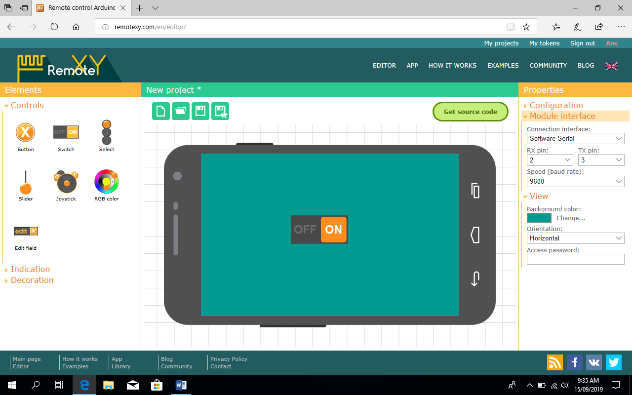
    FAQs

    Q1: Can I use a different temperature sensor? A1: Yes, you can use other temperature sensors like the DHT22 or LM35. You’ll need to adjust the code accordingly.
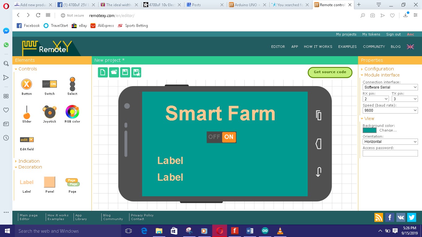
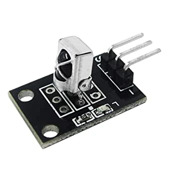
    Q2: Is it safe to control an AC fan with Arduino? A2: Yes, as long as you use a relay module to handle the high voltage and follow proper safety precautions.

    Q3: Can I add more speeds to the fan control? A3: Yes, you can modify the code to include more speed levels by adding additional relays and corresponding control logic.

    Q4: What type of IR remote can I use? A4: You can use any standard IR remote, such as an old TV remote. You’ll need to record the remote’s button codes for programming.

    Q5: Can I integrate this project with a smart home system? A5: Yes, with additional components like a WiFi module or Bluetooth, you can integrate the fan control into a broader smart home ecosystem.