
The goal of the project on “How to Design Motion Detector Smart Street Lights System is to control the amount of energy used when illuminating the pathways for motorists and pedestrians alike at night. At night, a lot of energy is usually used up to keep the street lights on all night. Most of the time, the illumination on these paths is not necessarily needed as there will be nobody using the roads. This project demonstrates how to design a motion detector smart street light system project so that it is smart enough to notice the movement of objects around it and light up the path so that people can see properly.
Introduction to Smart Street Lights
Smart street lights are an innovative solution designed to enhance urban infrastructure by integrating advanced technologies into traditional street lighting systems. These lights are equipped with sensors, communication modules, and control systems that allow them to operate more efficiently and adapt to real-time conditions. By leveraging technologies such as IoT (Internet of Things), smart street lights can adjust their brightness based on ambient light levels, detect motion, and even communicate with other smart devices. This not only improves energy efficiency but also enhances public safety and reduces maintenance costs.
Importance of Motion Detection in Street Lighting
Motion detection is a crucial feature in smart street lighting systems as it significantly contributes to energy conservation and public safety. By using motion sensors, such as Passive Infrared (PIR) sensors, street lights can automatically illuminate when they detect movement, ensuring that areas are well-lit only when necessary. This targeted lighting approach reduces energy consumption by preventing lights from being on continuously, thereby lowering electricity costs and minimizing environmental impact. Additionally, motion-activated lights can deter criminal activities and enhance the safety of pedestrians and drivers by providing adequate illumination only when needed.
Materials/Components
This smart street light control system project makes use of the Atmega328P-PU microcontroller, a motion detector sensor like a PIR sensor, and some AC light bulbs to sense the presence of pedestrians and illuminate their paths for them. For this project, we are going to need the following materials:
- 12v solid state relays………………………………………………………3pcs
- Atmega328P-PU microcontroller…………………………………….1pcs
- AC light bulbs 220/240V 200W………………………………………3pcs
- 12V power adapter………………………………………………………1pcs
- 5V or 12V 3-channel relay module……………………………………………….1pcs
You can buy the complete kit from our online store. or chat with us privately on WhatsApp.
The Circuit Diagram
To begin, we need to construct our MCU board. Read this previous post of ours to know how to build your own working standalone Arduino board. It would be very wise, however, to make sure that the power supply unit or DC supply adapter outputs enough current to power all the parts that run on DC.
Circuit Diagram Explanation
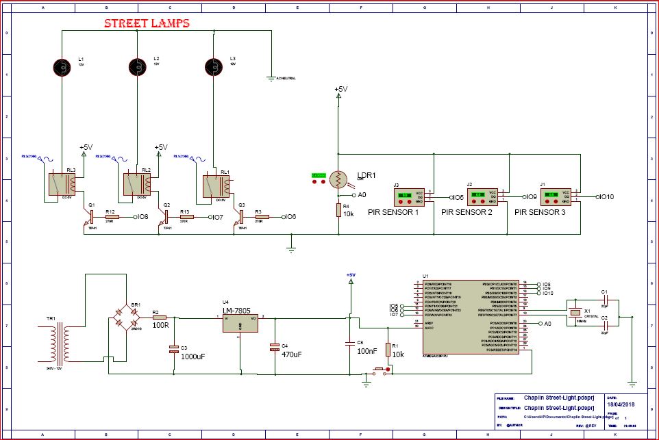
From the street light sensor circuit above, the power supply is producing 5V at 1A for the MCU, PIR sensors, and the 5V 3-channel relay module.
The MCU board is configured to control the 3-channel relay module through input/output (IO) pins 5, 6 and 7 respectively. While the PIR sensors are controlled via IO pins 8, 9 and 10 respectively.
The LDR sensor for this street light (Light Dependent Resistor), which we used here as optical sensor to differentiate when it is dark and when it is daytime, is connected to analog input pin 0 (A0) but voltage divider theorem (since the LDR is connected in series with a 10kΩ fixed resistor). The whole idea of this connection is to measure the rate of change in analog voltage as the resistance of the LDR changes due to the amount of light on its surface. The type of LDR used in this how to design motion detector smart street light system project has a negative coefficient of resistance; which means that as the amount of light on its flat surface increases, the resistance across it decreases.
read also Receding Hairline 101: Causes, Solutions, and Tips for Prevention
Source Code (Arduino Sketch)
The how to design motion detector smart street light system project would achieve its objective only when it is dark and when there is motion around it that needs to use the illumination it would give out. Hence, we write our program for the smart street project on the Arduino platform again as:
//Arduino source-code for Motion Detector Smart Street Light System project//
//the time we give the sensor to calibrate (10-60 secs according to the datasheet)
int calibrationTime = 10;

//the time when the sensor outputs a low impulse
long unsigned int lowIn;
//the amount of milliseconds the sensor has to be low
//before we assume all motion has stopped
long unsigned int pause = 200;

boolean lockLow = true;
boolean takeLowTime;

//the digital pin connected to the PIR sensor's output
int pirPin1 = 10;
int pirPin2 = 11;
int pirPin3 = 12;
int relay1 = 7;
int relay2 = 8;
int relay3 = 9;
int LDRVcc = 6;


void setup() {
/*we declare the input and output pins of the sensors
and actuators connected to d MCU */

  pinMode(pirPin1, INPUT);
  pinMode(pirPin2, INPUT);
  pinMode(pirPin3, INPUT);
  pinMode(relay1, OUTPUT);
  pinMode(relay2, OUTPUT);
  pinMode(relay3, OUTPUT);
pinMode(LDRVcc, OUTPUT);

//we wanted the LDR to kick start when the MCU is up and running,
//hence, we energized with one of the IO pins of the MCU.
//using a HIGH command
 digitalWrite(LDRVcc, HIGH);
//we start the serial monitor to see the readings of the sensors
 Serial.begin(9600);
 //give the PIR sensor some time to calibrate
  Serial.print("calibrating sensor ");
//for the calibration sequence that is displaying, we used a for loop
    for(int i = 0; i < calibrationTime; i++){
      Serial.print(".");
      delay(50);
}
}


 void loop(){
  //We start reading signals from the LDR connected to analog pin 0.
  int lightSense = analogRead(0);
//we print these readings on the serial monitor
  Serial.println(lightSense);
//with a delay of 0.5s between each value displayed
  delay(500);
//Using a simple if-statement we
  if(lightSense <= 300) {
    if(digitalRead(pirPin1) == HIGH){
//the led visualizes the sensors output pin state
       digitalWrite(relay1, HIGH);
       if(lockLow){
         //makes sure we wait for a transition to LOW before any further output is made:
         lockLow = false;

         }
         takeLowTime = true;
    }

else if(digitalRead(pirPin1) == LOW){
       digitalWrite(relay1, LOW);  //the led visualizes the sensors output pin state

       if(takeLowTime){
        lowIn = millis();          //save the time of the transition from high to LOW
        takeLowTime = false;       //make sure this is only done at the start of a LOW phase
        }
       //if the sensor is low for more than the given pause,
       //we assume that no more motion is going to happen
       if(!lockLow && millis() - lowIn > pause){
           //makes sure this block of code is only executed again after
           //a new motion sequence has been detected
           lockLow = true;

           }
       }

       if(digitalRead(pirPin2) == HIGH){
       digitalWrite(relay2, HIGH);   //the led visualizes the sensors output pin state
       if(lockLow){
         //makes sure we wait for a transition to LOW before any further output is made:
         lockLow = false;

         }
         takeLowTime = true;

    }
else if(digitalRead(pirPin2) == LOW){
//the led visualizes the sensors output pin state
       digitalWrite(relay2, LOW);
       if(takeLowTime){
//save the time of the transition from high to LOW
        lowIn = millis();
//make sure this is only done at the start of a LOW phase
        takeLowTime = false;               }
       //if the sensor is low for more than the given pause,
       //we assume that no more motion is going to happen
       if(!lockLow && millis() - lowIn > pause){
           //makes sure this block of code is only executed again after
           //a new motion sequence has been detected
           lockLow = true;

           }
       }

if(digitalRead(pirPin3) == HIGH){
       digitalWrite(relay3, HIGH);   //the led visualizes the sensors output pin state
       if(lockLow){
         //makes sure we wait for a transition to LOW before any further output is made:
         lockLow = false;
        Serial.println("---");
        Serial.print("motion detected at ");
         Serial.print(millis()/1000);
         Serial.println(" sec");
         delay(50);
         }
         takeLowTime = true;

    }

else if(digitalRead(pirPin3) == LOW){
//the led visualizes the sensors output pin state
       digitalWrite(relay3, LOW);

       if(takeLowTime){
//save the time of the transition from high to LOW
        lowIn = millis();
//make sure this is only done at the start of a LOW phase
        takeLowTime = false;
        }
       //if the sensor is low for more than the given pause,
       //we assume that no more motion is going to happen
       if(!lockLow && millis() - lowIn > pause){
           //makes sure this block of code is only executed again after
           //a new motion sequence has been detected
           lockLow = true;

           }
       }
    delay(50);
  }


  if (lightSense >= 301 ) {
    digitalWrite(relay1, LOW);
    digitalWrite(relay2, LOW);
    digitalWrite(relay3, LOW);
    if(takeLowTime){
//save the time of the transition from high to LOW
        lowIn = millis();
//make sure this is only done at the start of a LOW phase
        takeLowTime = false;
        }
       //if the sensor is low for more than the given pause,
       //we assume that no more motion is going to happen
       if(!lockLow && millis() - lowIn > pause){
           //makes sure this block of code is only executed again after
           //a new motion sequence has been detected
           lockLow = true;


  }

  }
 }
Further Explanation of Arduino Sketch:
We declared all our variables from line 3 through line 21, the calibration time for the PIR sensors was to 10 seconds according to the datasheet of the product. But the sensor emits a pulse and waits for an obstacle to reflect it by cutting into its line of projection. So we used a long variable unsigned to denote this. In the loop function, we have already noticed that during dark, the LDR displays values that are below 300 and when it experiences sufficient amount across its surface, its values rises way above 300. Using the if-statement we made a comparison as regards to when the latter following lines would be executed. The rest of the algorithm used for the Motion Detector Smart Street Lights System project are explained using comment line. And notice there is a repeated pattern for the three PIRs.
Connecting the AC Lamps
The AC bulbs are connected as shown in the circuit diagram. The relays: relay1, relay2 and relay3 acts as the bridge between the DC and the AC voltage. In other words for the AC bulbs to be turned on, the relays must be energized. The relay energizing voltages were rated 5V but 12V solid state relays are recommended to avoid arching between switching poles of the relays and burning out the filaments of the tungsten bulbs. A better choice would to go for energy saving lamps that uses AC to DC converters.
The working video is shown in the embed YouTube below.
The video demonstration shows that the model for this project was done on a copy off of a major type A road that has motion sensors attached to the base of each street light system. when movement was sensed, these street light come on and would go off in the absence of motion. The model was portable and made to be easily set up in less time frame.
Conclusion
We have done justice to How to design motion detector smart street lights system. What do you think? Can you build similar a project design? Let us know in the comment section if you followed this guide to achieve a successful project work. You can contact us and send us pictures and videos of your project design on WhatsApp, Twitter, Telegram, Instagram to and send us pictures or ask questions too.
Read More
- HOW TO GENERATE ELECTRICITY WITH FOOTSTEPS
- SOLAR POWERED IRRIGATION SYSTEM PROJECT
- ESP32 CAMERA FOR HOME AUTOMATION
- REMOVE JAPANESE HACK VIRUS FROM YOUR WEBSITE
FAQs
Q1: Can this system work outdoors?
Yes, but the PIR sensor must be weatherproof.
Q2: Can solar power be used?
Absolutely. A solar panel + battery makes it perfect for outdoor areas.
Q3: Does the system detect animals?
Yes. PIR sensors detect heat signatures from humans and animals.
Q4: Can this system be expanded?
Yes — IoT features (ESP32/NodeMCU) can be added to monitor lights remotely

