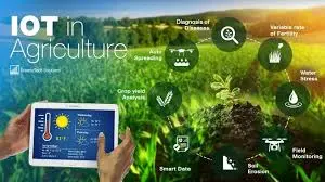
In this how to build a Wi-Fi based smart farm monitoring system project tutorial, we are going to be using ESP8266 Wi-Fi Module to create a wireless access point to view some farm parameters on a home garden model. We are going to be measuring soil moisture content, digital humidity and temperature readings of the green plants in the model garden. This smart agricultural monitoring system, using Arduino design, should also be able to notice when there is night time so that it can activate a grow lamp that can enhance further growth of the garden plants. So, in this Wi-Fi based Smart Farm Monitoring System project; we aim to achieve the following:
- Design a system that can measure the temperature around the environment of the plants and display this reading on a digital screen like the 16×2 LCD and also display it on a remote viewing mobile phone screen via Wi-Fi connection.
- The Wi-Fi based Smart Farm Monitoring System Project would be capable to take humidity readings around the plants and also the soil moisture content the plants.
- If these parameter readings are insufficient for the sustenance of the garden lives, the design is supposed to automatically adjust and compensate for that change. For example, if the soil moisture content is a little too dry above average reading; a DC pump would be turn on to water the plants automatically.
- Increase in temperature and thin air around the plants are also controlled with by letting water spray in the garden automatically.
- The whole system has a remote Wi-Fi based Control system that allows the user to controlled the Wi-Fi based Smart Farm Monitoring System Project using an Android smart phone.
Materials for the Project
For Power Supply design
- 12V, 2A step-down transformer……… 1pcs
- Bridge rectifier……………………………….. 1pcs
Capacitors:
- 4700µF 2pcs
- 470µF 2pcs
- 330µF 2pcs
- 100µF 2pcs
- 22pF 2pcs
- Voltage regulator LM317 1pcs
- Voltage regulator LM7805 (or LM232T) 1pcs
Resistors:
- 100Ω 5W 2pcs
- 1kΩ Potentiometer 2pcs
- 270Ω 2pcs
- 10kΩ 4pcs
- 10kΩ Potentiometer 1pcs
- LDR 1pcs
Alternatively, you can get a SMPS with 12V, ≥ 3A with two DC-DC buck converters. Regulate 1 DC-DC buck converter to output 12V and the other to source 5V respectively.
- Transistor TIP41 2pcs
- 5V Relay 1pcs
- Soil Moisture sensor module 1pcs
- Humidity Sensor DHT11 1pcs
- Wi-Fi module ESP8266 1pcs
- Push button 1pcs
- 12V DC pump 1pcs
- 16×2 LCD 1pcs
- 16Mhz Crystal oscillator 1pcs
- Atmega328P-PU 1pcs
The Circuit Diagram
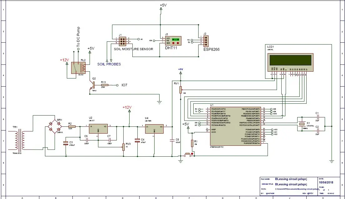
The Circuit Diagram Explanation
The circuit diagram is built around the Atmega328P-PU Chip and where the 16MHz crystal is connected, the ceramic capacitors connected too. In this standalone version design of Arduino, the pushbutton was used to reset the program.
The microcontroller was powered by a 5V from a 5V linear power supply. The same 5V was used to power the DHT11 sensor, the 5V relay module, soil moisture sensor and a 3.3V regulator that powers the ESP8266-01 (ESP-01).
The Soil Moisture Sensor Circuit Connection:
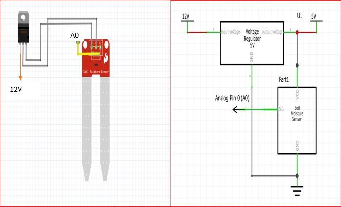
From the breadboard version and circuit diagram shown above, the humidity sensor is connected to the output pin of the 5V voltage regulator, and the signal pin is connected to the analog pin 0 of the Atmega328P-PU IC.
The Arduino Source Code (Sketch)
The following source code is coded into the Arduino IDE to effectively use the soil moisture sensor for the how to build a Wi-Fi based smart farm monitoring system.
 /*PROGRAM TO TEST AND ADJUST THE SOIL ,MOISTURE CONTENT FOR WI-FI BASED SMART FARM MONITORING SYSTEM PROJECT */
double sensor;
 void setup() {
Serial.begin(9600);
}

void soilMonitor() {
  // read the input on analog pin 0:
 sensor = analogRead(A0);
  // Convert the analog reading (which goes from 0 - 1023) to a range (0 - 100):
  double TP = map(sensor, 0.00, 1023.00, 100.00, 0.00);
serial.println(TP);
delay(500);
}
void loop() {
soilMonitor();
}
Source Code Explanation
To set and set the proper soil moisture content for our plants in the model garden, we code these syntax into the Arduino IDE, verify it for errors and upload it into out standalone MCU. We then open our serial monitor window and ensure that the communication between the MCU and the PC is set at 9600 baud rate as stated in the setup function.
We would see the readings on the serial monitor and we could calibrate them using the onboard potentiometer on the soil moisture sensor board.
In the first line, we declared the sensor read as a double because we are expecting floating point readings from the sensor. In the setup function, we started the serial communication to start displaying readings on the serial monitor screen. We created our own function soilMonitor() to read the signal the sensor pin connected to A0 of the MCU. We then mapped this reading such that the analog reading from the MCU which is from 0 to 1023 is mapped from 100 to 0. This means that; a value of 0.00 (since the reading is a floating point number) of the soil moisture sensor gets converted to 100.00 and the value of 1023.00 gets converted to 0.00.
Humidity and Temperature sensor DHT11 circuit connection:
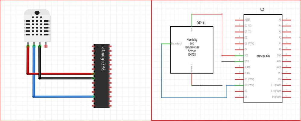
The DHT11 sensor is connected as shown in the the circuit diagram above, the pin 3( the data signal pin) of the the DHT11 is connected to pin 12 of the Atmega328P-PU IC while the Vcc and the GND pin are connected the 5V and the GND of the power supply. Which is also where the pin 7 and 8 of the Atmega328P-PU has option for the Vcc and the GND. The following sketch below is uploaded into the Arduino IDE to check and test for the accurate reading of the digital humidity and temperature sensor.
//Import  the DHT11 libs
#include <DHT.h>
#include <DHT_U.h>
// what digital pin are we connecting the DHT11 signal pin on the Atmega328
#define DHTPIN 6
// Define the type of dht you're using!
#define DHTTYPE DHT11
DHT dht(DHTPIN, DHTTYPE);
void setup() {
//begin the dht
dht.begin();
}
void loop() {
float h = dht.readHumidity();
  // Read temperature as Celsius (the default)
  float t = dht.readTemperature();
 int Temp = t;
 int Hum = h;
//print it out on the serial monitor window
serial.print(Hum);
  serial.print(Temp);
//delay for half a sec
delay(500);
}
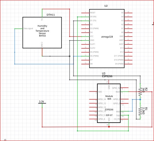
Connecting your ESP8266 Wi-Fi Module as an access point:
The ESP8266 module will be configured as a standalone WiFi access point in this Wi-Fi based smart farm monitoring system project. This means there will be no binding to an existing Wi-Fi network that is to be required for its mode of operation. To connect, the smartphone must be connected to the created access point though.
The circuit diagram shows the connection of the ESP8266 to the Atmega328P-PU as well as the DHT11.
Creating your Remote Control Wi-Fi App using RemoteXY Graphical User Interface
For how to create a free GUI app using RemoteXY and Arduino to control home appliances, read this post.
Open the RemoteXY editor by logging onto their webpage. We would advise creating an account so that your projects can be saved for future reference. Start your new project design. Name it what you will like. In our case, since this project was inspired by Dami, a final year student at landmark varsity, we just simply named it DAMI FARM.
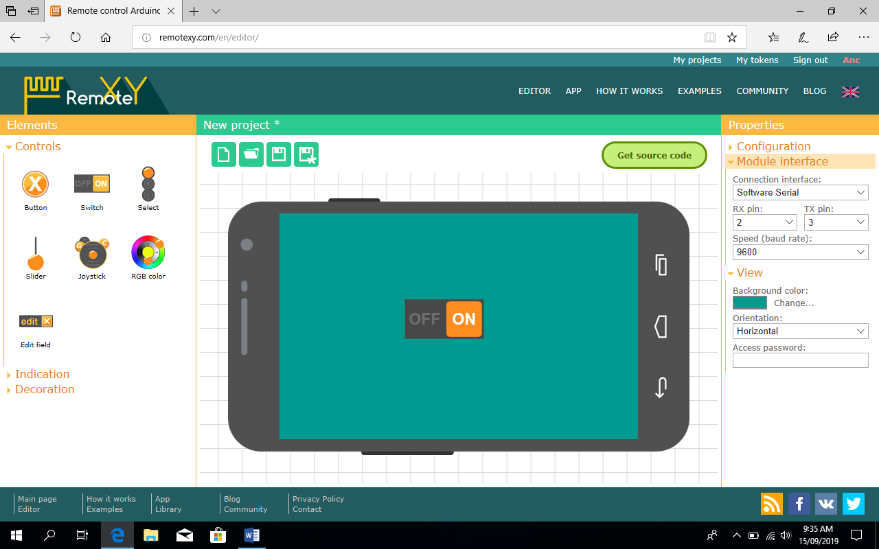
Next we selected a switch button for the user to manually turn on or off the DC pump when he or she feels like the parameters on the screen.
Highlight this switch button, then select the “Snap to pin” property to 7 (DC pump connection) value in the right pane of the “Element” tab.
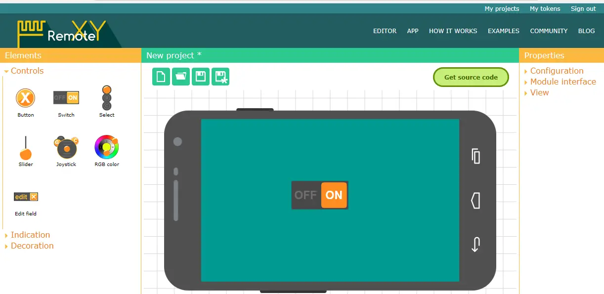
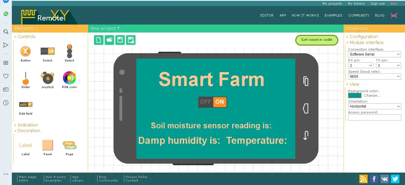
Again, drag a label and name it the project name. in this project, we had it as Smart farm as the caption just above it all.
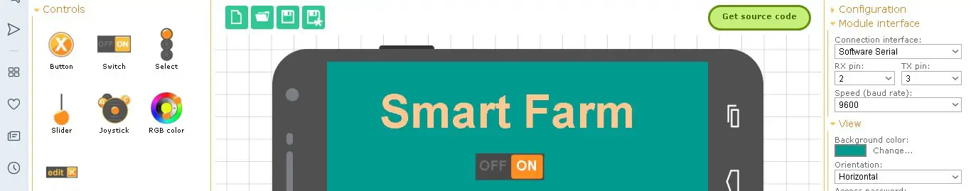
Add two more labels to the under the switch button icon and edit these labels as shown below.
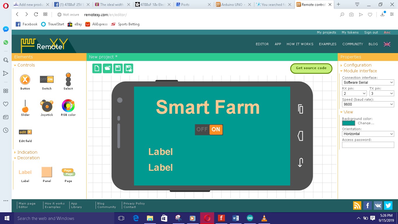
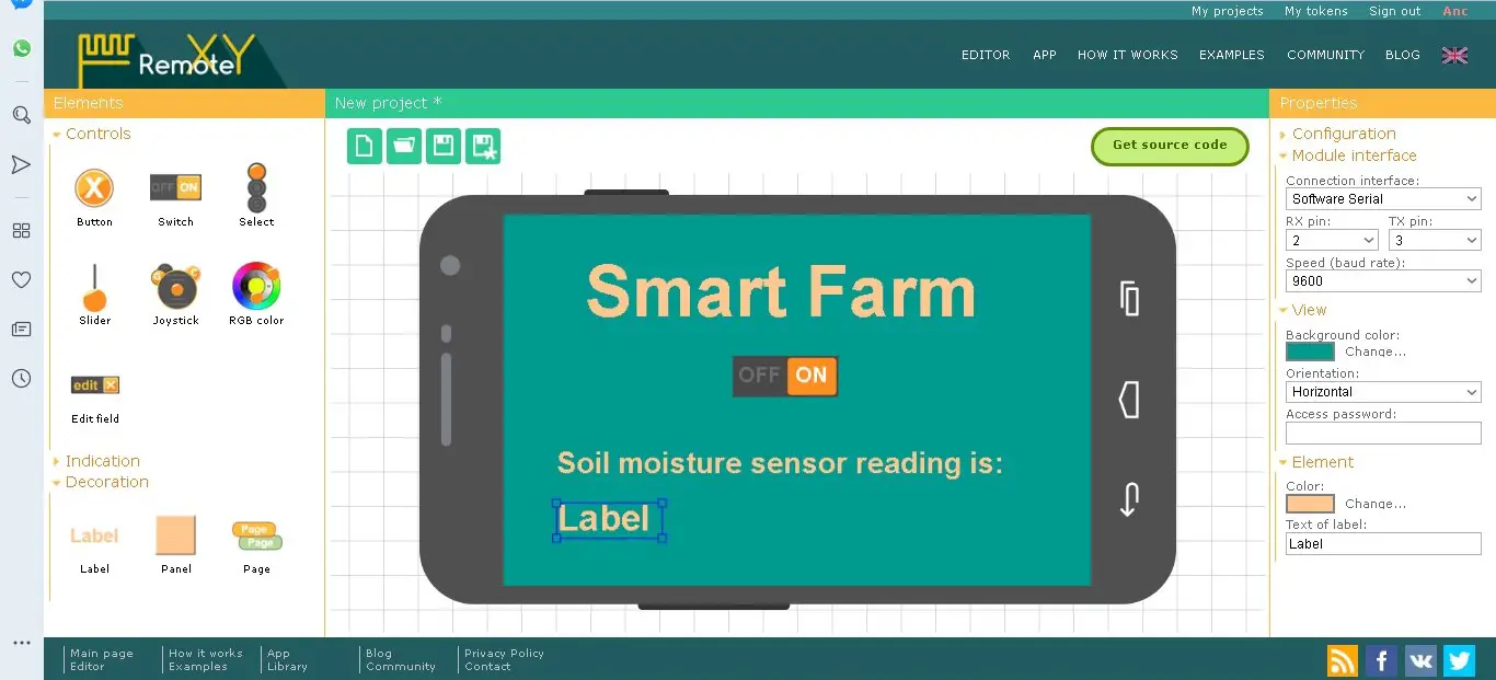
Click on each label and expand it. Go to the right pane in the Element column and in the “Text of label” edit the content to the one shown above.
Then move to the right pane, under the configuration tab, and select ESP8266 Wi-Fi. In that same pane, click on the “module interface” and set the connection interface as the hardware serial. This means we would use the RX and TX pins on the MCU. The speed should be set at a 115200 baud rate. A password should be set for the Wi-Fi access point in the password box as well as the future Wi-Fi access point name.
By clicking on the download code link, you will be taken to a page where you can download the source code. Open this in your Arduino IDE, download the remoteXY library and install it correctly.
To view the farm parameters of the How to Build a Wi-Fi based Smart Farm Monitoring System Project on the place where the design is mounted, we have to include an LCD on the project box. This means we have to code the LCD to display these readings.
The Complete Sketch:
//include the lcd lib
#include <LiquidCrystal.h>
//include the adafruit lib for dht11
#include <Adafruit_Sensor.h>
//include the dth11 lib
#include <DHT.h>
#include <DHT_U.h>
/*
-- Smart Farm --
*/
// RemoteXY select connection mode and include library
#define REMOTEXY_MODE__ESP8266_HARDSERIAL_POINT
//include the remotexy lib
#include <RemoteXY.h>
// RemoteXY connection settings
#define REMOTEXY_SERIAL Serial
#define REMOTEXY_SERIAL_SPEED 115200
#define REMOTEXY_WIFI_SSID "DAMI FARM"
#define REMOTEXY_WIFI_PASSWORD "12345678"
#define REMOTEXY_SERVER_PORT 6377
// RemoteXY configurate
#pragma pack(push, 1)
uint8_t RemoteXY_CONF[] =
{ 255,1,0,47,1,85,0,8,45,2,
2,1,37,28,16,8,20,31,26,12,
2,32,31,31,79,78,0,79,70,70,
0,67,0,1,40,98,6,1,59,61,
7,31,26,101,67,0,1,48,98,6,
1,73,61,7,2,26,101,67,0,1,
56,98,6,1,88,61,7,13,26,101,
129,0,6,2,89,16,5,5,55,10,
2,83,109,97,114,116,32,70,97,114,
109,0 };
// this structure defines all the variables of your control interface
struct {
// input variable
uint8_t SW1; // =1 if switch ON and =0 if OFF
// output variable
char SCREEN1[101]; // string UTF8 end zero
char SCREEN2[101]; // string UTF8 end zero
char SCREEN3[101]; // string UTF8 end zero
// other variable
uint8_t connect_flag; // =1 if wire connected, else = 0
} RemoteXY;
#pragma pack(pop)
/////////////////////////////////////////////
// END RemoteXY include //
/////////////////////////////////////////////
#define PIN_SW1 7
// what digital pin we're connected to
#define DHTPIN 6
// Uncomment whatever type you're using!
#define DHTTYPE DHT11 // DHT 11
DHT dht(DHTPIN, DHTTYPE);
// initialize the library with the numbers of the interface pins
LiquidCrystal lcd(12, 11, 5, 4, 3, 2);
void setup()
{
RemoteXY_Init ();
pinMode (PIN_SW1, OUTPUT);
dht.begin();
lcd.begin(16, 2);
// Print a message to the LCD.
lcd.print("Smart FARM Project");
lcd.setCursor(1,4);
lcd.print("by DAMILOLA");
delay(3000);
lcd.clear();
}
void soilMonitor() {
// read the input on analog pin 0:
double sensor = analogRead(A0);
// Convert the analog reading (which goes from 0 - 1023) to a range (0 - 100):
double TP = map(sensor, 0, 1023, 100, 0);
//dtostrf(TP, 0, 2, RemoteXY.SCREEN2);//SEND VALUE OF ADC TO SMART PHONE
int soil = TP;
if((soil < 40) || (soil == 40) && (RemoteXY.SW1 == 0) ) {
digitalWrite(PIN_SW1, HIGH);
strcpy (RemoteXY.SCREEN3, "Pump in AUTO Mode");
}
}
void loop()
{
RemoteXY_Handler ();
soilMonitor();
// read the input on analog pin 0:
double sensor = analogRead(A0);
// Convert the analog reading (which goes from 0 - 1023) to a range (0 - 100):
double TP = map(sensor, 0, 1023, 100, 0);
//dtostrf(TP, 0, 2, RemoteXY.SCREEN2);//SEND VALUE OF ADC TO SMART PHONE
int soil = TP;
//sprintf (RemoteXY.SCREEN2, "The Temperature is: %d'C___Farm Humidity is: %d", TEMP, HUM);
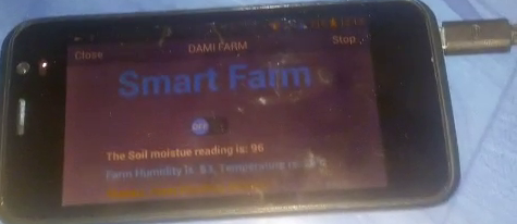
sprintf (RemoteXY.SCREEN1, "The Soil moistue reading is: %d", soil);
if ((soil < 60) && (RemoteXY.SW1 ==1))
{
digitalWrite(PIN_SW1, HIGH);
strcpy (RemoteXY.SCREEN3, "Manual Override: Pump Pumping");
}
if ((soil > 40) && (soil < 60) && (RemoteXY.SW1 == 0))
{
digitalWrite(PIN_SW1, LOW);
strcpy (RemoteXY.SCREEN3, "Pump is shut-off");
}
if((soil > 60) && (RemoteXY.SW1 ==1)) {
digitalWrite(PIN_SW1, LOW);
strcpy (RemoteXY.SCREEN3, "Warning! Farm Flooded, System AUTO Shut Off pump");
}
if((soil > 60) && (RemoteXY.SW1 ==0)) {
digitalWrite(PIN_SW1, LOW);
strcpy (RemoteXY.SCREEN3, "Thanks, Farm Flooding Averted.");
}
float h = dht.readHumidity();
// Read temperature as Celsius (the default)
float t = dht.readTemperature();
int Temp = t;
int Hum = h;
// Check if any reads failed and exit early (to try again).
if (isnan(h) || isnan(t)) {
strcpy (RemoteXY.SCREEN2, "Warning!!! Failed to read from DHT sensor!");
return;
}
sprintf (RemoteXY.SCREEN2, "Farm Humidity is: %d, Temperature is: %d'C", Hum, Temp);
lcd.setCursor(0,0);
lcd.print("HUM: TEMP: SOIL:");
lcd.setCursor(2,1);
lcd.print(Hum);
lcd.setCursor(7,1);
lcd.print(Temp);
lcd.setCursor(13,1);
lcd.print(soil);
}
The RemoteXY APP
To communicate wirelessly in this How to Build a Wi-Fi based Smart Farm Monitoring System Project; Go to the website or Playstore to download the remoteXY app.
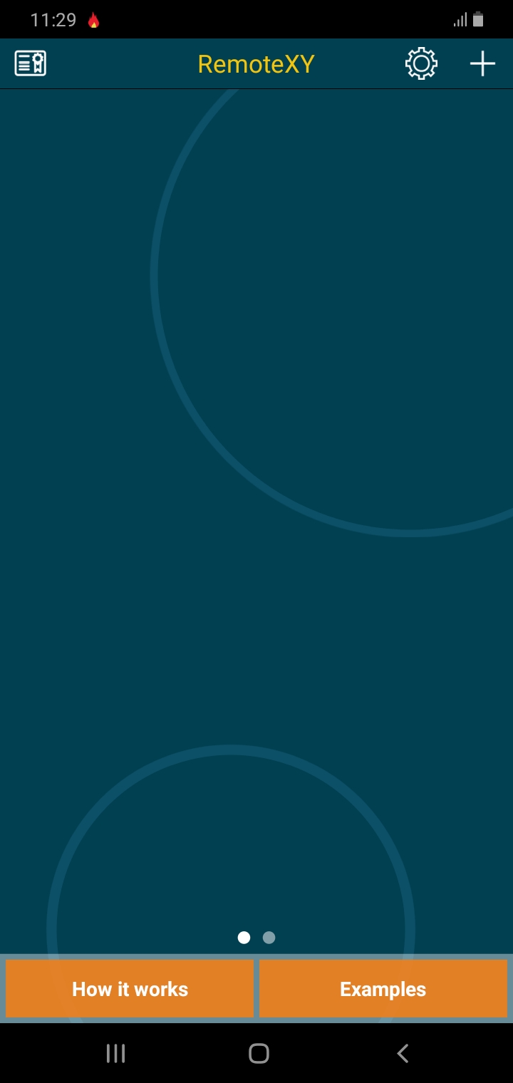
Run your sketch and then open the app and click on the add or (+) button.
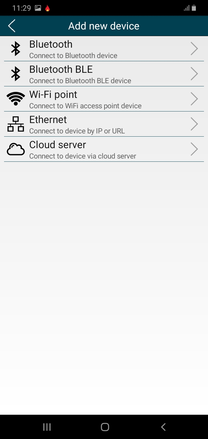
Click on the Wi-Fi access point option available in the lists of options.
This would open another page that shows something like this shown below.
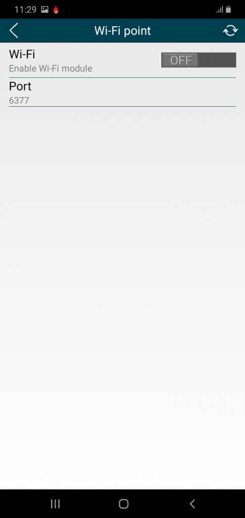
Turn on your Wi-Fi network (if it is not turned on) and search for the Wi-Fi access point network. This is very important for this How to Build a Wi-Fi based Smart Farm Monitoring System Project to work
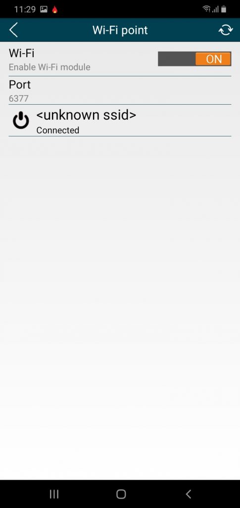
You wuld see the network next, connect to it and start viewing and accessing you project remotely via Wi-Fi.
Check out the video of how the project is working below:
Conclusion
We have done justice to How to Build a Wi-Fi based Smart Farm Monitoring System Project. What do you think? Can you build similar a project design? Let us know in the comment section if you followed this guide to achieve a successful project work. You can contact us and send us pictures and videos of your project design on WhatsApp, Twitter, Telegram, Instagram to and send us pictures or ask questions too.
Read More
- HOW TO GENERATE ELECTRICITY WITH FOOTSTEPS
- SOLAR POWERED IRRIGATION SYSTEM PROJECT
- ESP32 CAMERA FOR HOME AUTOMATION
- REMOVE JAPANESE HACK VIRUS FROM YOUR WEBSITE
FAQs on How to Build a Wi-Fi Based Smart Farm Monitoring System Project
1. What components are needed to build a Wi-Fi-based smart farm monitoring system?
To build this project, you will typically need an ESP8266 or ESP32 Wi-Fi module, an Arduino board, various sensors (such as soil moisture, temperature, humidity, and light sensors), a relay module to control water pumps or other devices, and a power supply. Additionally, you may need a cloud platform or IoT service to view real-time data remotely.
2. How does a Wi-Fi-based smart farm monitoring system work?
The system collects data from sensors placed throughout the farm, such as soil moisture or temperature. The Wi-Fi module (ESP8266 or ESP32) sends this data to an IoT cloud platform where users can monitor the farm conditions remotely through a mobile app or web interface. Automated actions like irrigation can be triggered based on sensor data.
3. Can this system be used to automate irrigation and other farm tasks?
Yes, you can integrate relays or automated switches into the system to control irrigation systems, lights, or other equipment. By setting thresholds in the code (e.g., soil moisture levels), the system can automatically turn on or off the irrigation system based on real-time data.
4. How can I access the farm data remotely?
You can access real-time farm data through any device connected to the internet, such as a smartphone or computer. The system uses a cloud-based IoT platform like ThingSpeak, Blynk, or custom-built web servers to display the data. You can monitor and control the farm from anywhere with Wi-Fi.
5. How do I ensure that my Wi-Fi-based farm monitoring system is reliable?
To ensure reliability, use a stable Wi-Fi connection, secure your system with proper encryption methods, and select sensors that are designed for outdoor use and can withstand farm conditions (e.g., water-resistant sensors). Additionally, regularly maintain the system to check for sensor malfunctions or network interruptions.

