Tag: Arduino

  • USING SIM800L GSM MODULE AND ARDUINO TO SEND SMS AND MAKE CALLS.

    USING SIM800L GSM MODULE AND ARDUINO TO SEND SMS AND MAKE CALLS.

    In this project tutorial, we will be using a SIM800L with Arduino to send, receive SMS and also make calls. The design would use the following materials, modules and components as listed below. They all can be ordered from the Smartech online store.

    Materials and Components

    • SIM800L GSM Module
    • SIM Card
    • Lipo- Battery – 3.7v. (Charged to about 3.8v to 4.2v)
    • Arduino Uno

    WHAT IS SIM800L GSM MODULE?

    make call and send SMS
    SIM800L GSM Module

    SIM800L is a small cellular module that can transmit GPRS, send and receive SMS, and make and receive voice calls. This is used in a large IoT project. The operating voltage output (output maximum voltage) of SIM800L GSM Modules is approximately 3.7 to 4.2 volts. The SIM800L has about 12 pins, which includes – GND, VCC, RXD , TRD, RST, NET and more.

    The SIM800L has a LED on it, the indications of the light are as follows :

    • Every 1sec, blink – Although the module is operating, it has not yet established a connection with the cellular network.
    • Every 2secs, blink – Your required GPRS data connection has been established.
    • Every 3secs, blink – The module is in communication with the cellular network and is capable of sending and receiving voice and SMS.

    HOW TO CONNECT SIM800L GSM MODULE WITH ARDUINO UNO

    We can connect SIM800L with Arduino Uno in the following ways :

    • Software  Serial Connection
    • Hardware Serial Connection

    SOFTWARE SERIAL CONNECTION

    Software Serial Connection makes use of digital pins on the Arduino that are connected to the SIM800L’s TXD and RXD. In this project, we will use digital pins 11 and 12, which are connected to the SIM800’s TXD and RXD. The Lipo-battery has a Vcc of 3.7 volts (which should be charged to about 4 to 4.2 volts to power the SIM800L) and all GND, including the Arduino, SIM800L, and Lipo-Battery, should have a common ground (GND).

    N.B : Insert the SIM to the SIM800L

    CONNECTION MODE :

    ARDUINOSIM800L GSM MODULELIPO BATTERY (3.7v)
    GNDGNDGND
                              –VCCVCC
    D12TXD
    D13RXD

    HARDWARE SERIAL CONNECTION

    Hardware serial connection involves the use of TXD and RXD on the Arduino, which are connected to the TXD and RXD of the SIM800L. In this project, we will use the Arduino’s TXD and RXD pins, which will be connected to the SIM800’s RXD and TXD. The Lipo-battery has a Vcc of 3.7 volts (which should be charged to about 4 to 4.2 volts to power the SIM800L) and all GND, including the Arduino, SIM800L, and Lipo-Battery, should have a common ground (GND).

    CONNECTION MODE :

    ARDUINOSIM800L GSM MODULELIPO BATTERY (3.7v)
    GNDGNDGND
                              –VCCVCC
    RXDTXD
    TXDRXD

    USING SIM800L GSM MODULE AND ARDUINO TO SEND SMS

    The circuit diagram to achieve this feat should be the software serial connection schematic diagram shown above. We recommend this, so that both the program code can be upload simultaneously as the connections are still intact.

    Arduino Sketch (Source Code)

    #include <SoftwareSerial.h>
    
    //Create software serial object to communicate with SIM800L
    SoftwareSerial mySerial(12, 13);
    
    void setup() {
      //Begin serial communication with Arduino and Arduino IDE (Serial Monitor)
      Serial.begin(9600);
      
      //Begin serial communication with Arduino and SIM800L
      mySerial.begin(9600);
    
      Serial.println("Initializing..."); 
      delay(1000);
    sendSMS();
    delay(22000);
    }
    
    void sendSMS(){
      mySerial.println("AT"); //Once the handshake test is successful, it will back to OK
      updateSerial();
    
      mySerial.println("AT+CMGF=1"); // Configuring TEXT mode
      updateSerial();
      mySerial.println("AT+CMGS=\"+ZZ8xxxxx\"");//change ZZ with country code and xxxxxxxxxxx with phone number to sms
      updateSerial();
      mySerial.print("Hello, can you read me?");// + String(tg)); //text content
      updateSerial();
      mySerial.write(26);
    }
    
    
    void loop() {
      }
    
    void updateSerial(){
      delay(500);
      while (Serial.available()) 
      {
        mySerial.write(Serial.read());//Forward what Serial received to Software Serial Port
      }
      while(mySerial.available()) 
      {
        Serial.write(mySerial.read());//Forward what Software Serial received to Serial Port
      }
    }
    

    Results

    USING SIM800L GSM MODULE AND ARDUINO TO RECEIVE SMS

    #include <SoftwareSerial.h>
    // Configure software serial port
    SoftwareSerial MySerial(12, 13); //tx and rx
    
    // Relay connected to pin 12
    const int lampPin1 = 7;
    const int lampPin2 = 8;
    const int lampPin3 = 9;
    
    String textMessage;
    
    void setup() {
       // Set LED as OUTPUT
      pinMode(lampPin1, OUTPUT);
      pinMode(lampPin2, OUTPUT);
      pinMode(lampPin3, OUTPUT);
    
      // By default the LED is off
      digitalWrite(lampPin1, LOW);
      digitalWrite(lampPin2, LOW);
      digitalWrite(lampPin3, LOW);
     
      // Initializing serial commmunication
      Serial.begin(9600);
      MySerial.begin(9600);
    
      Serial.print("SIM800 ready...");
      delay(1000);
       // AT command to set SIM900 to SMS mode
      MySerial.print("AT+CMGF=1\r");
      delay(100);
      // Set module to send SMS data to serial out upon receipt
      MySerial.print("AT+CNMI=2,2,0,0,0\r");
      delay(100);
    }
    
    
    String controlCommandFxn(){
      //create a Command for SMS
     
      if(MySerial.available()>0){
        textMessage = MySerial.readString();
        Serial.print(textMessage);    
        delay(10);
    }
    return checkStatus;
    }
    
    void loop(){
    controlCommandFxn();
    }
    
    
    // Clearing the Buffer in the SMS section
    void updateSerial(){
      delay(500);
      while (Serial.available()) 
      {
        MySerial.write(Serial.read());//Forward what Serial received to Software Serial Port
      }
      while(MySerial.available()) 
      {
        Serial.write(MySerial.read());//Forward what Software Serial received to Serial Port
      }
    }
    

    Results

    USING SIM800L GSM MODULE AND ARDUINO TO MAKE CALLS

    #include <SoftwareSerial.h>
    
    //Create software serial object to communicate with SIM800L
    SoftwareSerial mySerial(12, 13);
    
    void setup() {
      //Begin serial communication with Arduino and Arduino IDE (Serial Monitor)
      Serial.begin(9600);
      
      //Begin serial communication with Arduino and SIM800L
      mySerial.begin(9600);
    
      Serial.println("Initializing..."); 
      delay(1000);
     makeCall();
     delay(5000);
    }
    
    void makeCall(){
      mySerial.println("AT"); //Once the handshake test is successful, i t will back to OK
      updateSerial();
      
      mySerial.println("ATD+ +ZZZxxxxxxx;"); //  change ZZ with country code and xxxxxxxxxxx with phone number to dial
      updateSerial();
      delay(20000); // wait for 20 seconds...
      mySerial.println("ATH"); //hang up
      updateSerial();
    }
    
    
    void loop() {
      }
    
    void updateSerial(){
      delay(500);
      while (Serial.available()) 
      {
        mySerial.write(Serial.read());//Forward what Serial received to Software Serial Port
      }
      while(mySerial.available()) 
      {
        Serial.write(mySerial.read());//Forward what Software Serial received to Serial Port
      }
    }
    

    Results

    Conclusion

    So far, we have discussed about using a SIM800L with Arduino to send, receive SMS and also make calls. What do you think about this project tutorial? Can you reproduce it? If you did, we would love to see your work. leave us a comment down below or you can send us pictures or videos of your work on the Telegram group, WhatsApp handle. You can chat us any time. See you on the next tutorial.
    Thank you.

    Read More

  • How to Design Arduino Social Distancing Bar Project

    How to Design Arduino Social Distancing Bar Project

    How to Design Arduino Social Distancing Bar Project

    In the wake of the COVID-19 pandemic, social distancing has become a crucial measure to curb the spread of the virus. Public spaces, such as bars and restaurants, have been particularly affected by these restrictions, necessitating innovative solutions to maintain safe social interactions. This guide delves into the design and implementation of an Arduino-based social distancing bar project, providing a step-by-step approach to creating a system that monitors and enforces social distancing guidelines within a bar setting.

    Understanding the Social Distancing Bar Project

    How to Design Arduino Social Distancing Bar Project

    The Arduino Social Distancing Bar Project aims to utilize the power of Arduino technology to create a system that ensures patrons maintain appropriate physical distance from one another. This system comprises ultrasonic sensors, LEDs, and an Arduino microcontroller to detect and signal potential violations of social distancing norms.

    Essential Components for the Social Distancing Bar Project

    To construct this project, you will need the following components:

    Hardware Setup:

    How to Design Arduino Social Distancing Bar Project
    • Connect the Arduino Uno to the breadboard using jumper wires.
    • Connect the ultrasonic sensors to the Arduino:
      • Connect the trigger pin of the ultrasonic sensor to pin 12 of the Arduino.
      • Connect the echo pin of the ultrasonic sensor to pin 13 of the Arduino.
    • Connect the LEDs to the Arduino:
      • Connect the anode of the red LED to pin 9 of the Arduino.
      • Connect the cathode of the red LED to ground on the breadboard.
      • Connect the anode of the green LED to pin 10 of the Arduino.
      • Connect the cathode of the green LED to ground on the breadboard.

    Arduino Programming

    1. Open the Arduino IDE software on your computer.
    2. Create a new Arduino sketch.
    3. Include the necessary libraries for ultrasonic sensors and LEDs:
      • Include the NewPing library for ultrasonic sensors.
      • Include the FastLED library for controlling LEDs.
    4. Define the pins for the ultrasonic sensors and LEDs.
    5. Set up the serial communication for debugging purposes.
    6. Initialize the ultrasonic sensors and LEDs.
    7. Write the main loop function that continuously measures the distance between patrons using the ultrasonic sensors:
      • Trigger the ultrasonic sensor to send a sound wave.
      • Measure the time it takes for the sound wave to return.
      • Calculate the distance based on the time measurement.
      • Check if the measured distance is less than the minimum acceptable social distance (e.g., 6 feet).
      • If the distance is too close, turn on the red LED to indicate a violation.
      • If the distance is within the acceptable range, turn on the green LED to indicate compliance.

    Testing and Deployment

    How to Design Arduino Social Distancing Bar Project
    • Connect the Arduino to your computer using a USB cable.
    • Upload the Arduino sketch to the Arduino board.
    • Test the system by placing objects at different distances from the ultrasonic sensor and observing the corresponding LED indications.
    • Once testing is complete, deploy the system in the bar environment by mounting the ultrasonic sensors and LEDs strategically to cover the desired area.

    Conclusion

    The Arduino Social Distancing Bar Project provides a practical and effective solution to maintaining social distancing guidelines within bars and similar public spaces. By utilizing ultrasonic sensors, LEDs, and an Arduino microcontroller, the system effectively monitors and signals potential violations, ensuring patrons adhere to recommended safety measures. This project demonstrates the versatility of Arduino technology in addressing real-world challenges and promoting responsible behavior in social settings.

    Read More

    FAQs

    What is the minimum acceptable social distance for the system?

    The minimum acceptable social distance can be adjusted in the Arduino sketch to match the current guidelines or specific requirements of the bar environment.

    Can the system be integrated with other bar management systems?

    Yes, the system can be integrated with other bar management systems to provide real-time data on social distancing compliance, enabling proactive measures to maintain safety.

    What is the power consumption of the system?

    The power consumption of the system is relatively low, primarily due to the efficient operation of the Arduino microcontroller and the low power consumption of the ultrasonic sensors and LEDs.

    What are the limitations of the system?

    Environmental factors such as noise and interference can potentially affect the system’s performance. To mitigate these limitations, consider the following strategies:

    • Noise Reduction: Choose ultrasonic sensors with higher immunity to noise interference.
    • Strategic Sensor Placement: Mount the sensors in locations less prone to environmental noise, such as away from speakers or air conditioning vents.
    • Data Filtering: Implement data filtering techniques in the Arduino sketch to remove noise and outliers from the sensor readings.
    • Calibration: Regularly calibrate the ultrasonic sensors to ensure accurate distance measurements.

    Additional Enhancements and Future Directions

    The Arduino Social Distancing Bar Project can be further enhanced and expanded in various ways:

    • Wireless Communication: Incorporate wireless communication modules (e.g., Wi-Fi or Bluetooth) to enable remote monitoring and control of the system.
    • Data Visualization: Develop a web-based dashboard or mobile app to visualize real-time social distancing data and provide insights into patron behavior.
    • Integration with Bar Signage: Integrate the system with bar signage to display social distancing reminders or warnings when violations occur.
    • Adaptive Social Distancing: Implement algorithms to dynamically adjust the minimum acceptable social distance based on real-time occupancy and crowd density.
    • Contact Tracing Capabilities: Explore integrating contact tracing capabilities to identify potential exposure risks if a patron is later found to be infected.
  • IoT Based Manhole Lid Detection With Surveillance Camera

    IoT Based Manhole Lid Detection With Surveillance Camera

    Watch the YouTube video here to get the workings of the Project design first hand experience.

    manhole lid surveillance project
    manhole lid surveillance project

    The block diagram above illustrates the processes involved in the IoT manhole lid surveillance project design. The project design is about detecting illegal and unauthorized entry into manholes. The design is attached at the end of the manhole, pointed and rigged to detect unapproved motion at the manhole entrance. Once armed, any illegal entry notify the admin via call, then a text message and telegram chat that contains the pictures of the person entering the manhole.

    manhole lid surveillance project

    The manhole lid surveillance project design uses Telegram as its IoT platform, making use of a Telegram bot, to notify the admin when there is activity at the manhole point without proper clearance. As well as sending snapshots of the activities happening at the entrance point. Since we can’t go poking around in actual manholes to implement this, we used a bucket to model a prototype of this to show how it works.

    Components and Materials Needed for Manhole Lid Surveillance Project

    ITEM DESCRIPTIONQUANTITY
    LiPo CHARGING MODULE1
    ESP32 CAM BOARD1
    LEDs1
    RESISTORS2
    LiPO BATTERY1
    CONNECTING WIRES1 Yard
    CASING1
    VERO BOARD1
    SOLDER1
    SOLDERING IRON1
    PIEZO BUZZER1
    MISCELLANEOUS 
    list of components for the manhole lid surveillance project

    The system design has a development (Dev) board from the Expressif company; namely, the ESP32 Cam Dev board. The development board ESP32 Cam is used to take real time photographs on the mobile app  using its onboard OV2460 Camera module attached to it and also offers users access to Arm and Unarm the device remotely from anywhere in the world. The Motion sensor module was connected to the Dev. Board so was the contact trip system such that the former would detect motion and send a captured picture of such motion while the lid contact trip mechanism would alert the user once the lip was opened during its Armed state with the backed up photograph  captured during the time of someone  opening the lip.

    Read More Posts Like These

    Schematic Diagram Manhole Lid Surveillance Project

    circuit diagram for manhole lid surveillance project

    Explanation of Schematic Diagram

    The circuit diagram shown above uses the the GSM module SIM800L EVB type connected the development board ESP32 Cam in serial communication protocol. The Rx (receiver pin) of the SIM800L is connected to IO13 pin of the ESP32 cam while the TX (Transmitter pin) of the SIM800L is connected to IO12 of the EPS32 Cam dev board. The GSM module can be powered by a 5V DC power rail so can the ESP32 Cam board. All connections are made in parallel.

    To deter off burglars or illegal entry into the manhole, we used a buzzer to sound an alarm when an illegal entry is made. This is connected as common emitter follower to the NPN transistor shown above in the schematic diagram. We kept the other NPN transistor connected to the IO15 pin of the ESP32 Cam (this pin was programed to be active LOW), so that it can trip or send a signal of motion is detected by the PIR sensor. The reed switch is connected to to the top or lid of the modelled manhole so that it can create a trigger when the lip is removed illegally.

    Assembling The Project Design

    manhole lid surveillance project: assembling the project design

    We used a 3 by 6 inch box, and cut a hole in it and we placed the PIR motion sensor. We also cut out a hole by the side of the model manhole where we can affix this bulge of the PIR sensor. The other components were connected according to the schematic diagram.

    We placed the camera at the bottom of the bucket where it can have direct view of the person opening the lid and entering the manhole. The design is also powered by a rechargeable LiPo battery, which means it can run on its own.

    Programming The Manhole Lid Surveillance Project

    #include <Arduino.h>
    #include <WiFi.h>
    #include <WiFiClientSecure.h>
    #include "soc/soc.h"
    #include "soc/rtc_cntl_reg.h"
    #include "esp_camera.h"
    #include <UniversalTelegramBot.h>
    #include <ArduinoJson.h>
    
    const char* ssid = "AncII";
    const char* password = "eureka26";
    
    // Initialize Telegram BOT
    String BOTtoken = "5372751881:AAHV3RKHUXZFYgYT4k7h25XdQMlR1CR1ruI";  // your Bot Token (Get from Botfather)
    
    String CHAT_ID = "1141844942";
    
    bool sendPhoto = false;
    bool engaged = false;
    bool flashState = 0;
    
    WiFiClientSecure clientTCP;
    UniversalTelegramBot bot(BOTtoken, clientTCP);
    
    #define FLASH_LED_PIN 4
    #define motionSensor 14
    #define lidCoverSensor 15
    #define buzzer 16
    //coonect GSM Module RX pin to ESP32 Pin 12
    //connect GSM Module TX pin to ESP32 Pin 13
    #define rxPin 12
    #define txPin 13
    #define BAUD_RATE 115200
    HardwareSerial sim800(1);
    
    int readPirSensor, readReedSensor;
    
    
    //Checks for new messages every 1 second.
    int botRequestDelay = 1000;
    unsigned long lastTimeBotRan;
    
    //CAMERA_MODEL_AI_THINKER
    #define PWDN_GPIO_NUM     32
    #define RESET_GPIO_NUM    -1
    #define XCLK_GPIO_NUM      0
    #define SIOD_GPIO_NUM     26
    #define SIOC_GPIO_NUM     27
    
    #define Y9_GPIO_NUM       35
    #define Y8_GPIO_NUM       34
    #define Y7_GPIO_NUM       39
    #define Y6_GPIO_NUM       36
    #define Y5_GPIO_NUM       21
    #define Y4_GPIO_NUM       19
    #define Y3_GPIO_NUM       18
    #define Y2_GPIO_NUM        5
    #define VSYNC_GPIO_NUM    25
    #define HREF_GPIO_NUM     23
    #define PCLK_GPIO_NUM     22
    
    
    void configInitCamera(){
      camera_config_t config;
      config.ledc_channel = LEDC_CHANNEL_0;
      config.ledc_timer = LEDC_TIMER_0;
      config.pin_d0 = Y2_GPIO_NUM;
      config.pin_d1 = Y3_GPIO_NUM;
      config.pin_d2 = Y4_GPIO_NUM;
      config.pin_d3 = Y5_GPIO_NUM;
      config.pin_d4 = Y6_GPIO_NUM;
      config.pin_d5 = Y7_GPIO_NUM;
      config.pin_d6 = Y8_GPIO_NUM;
      config.pin_d7 = Y9_GPIO_NUM;
      config.pin_xclk = XCLK_GPIO_NUM;
      config.pin_pclk = PCLK_GPIO_NUM;
      config.pin_vsync = VSYNC_GPIO_NUM;
      config.pin_href = HREF_GPIO_NUM;
      config.pin_sscb_sda = SIOD_GPIO_NUM;
      config.pin_sscb_scl = SIOC_GPIO_NUM;
      config.pin_pwdn = PWDN_GPIO_NUM;
      config.pin_reset = RESET_GPIO_NUM;
      config.xclk_freq_hz = 20000000;
      config.pixel_format = PIXFORMAT_JPEG;
    
      //init with high specs to pre-allocate larger buffers
      if(psramFound()){
        config.frame_size = FRAMESIZE_UXGA;
        config.jpeg_quality = 10;  //0-63 lower number means higher quality
        config.fb_count = 2;
      } else {
        config.frame_size = FRAMESIZE_SVGA;
        config.jpeg_quality = 12;  //0-63 lower number means higher quality
        config.fb_count = 1;
      }
      
      // camera init
      esp_err_t err = esp_camera_init(&config);
      if (err != ESP_OK) {
        Serial.printf("Camera init failed with error 0x%x", err);
        delay(1000);
        ESP.restart();
      }
    
      // Drop down frame size for higher initial frame rate
      sensor_t * s = esp_camera_sensor_get();
      s->set_framesize(s, FRAMESIZE_CIF);  //UXGA|SXGA|XGA|SVGA|VGA|CIF|QVGA|HQVGA|QQVGA
    }
    
    
    bool pirSensor() {
      //read the pushbutton value into a variable
       readPirSensor = digitalRead(motionSensor);
    //   Serial.print("Motion Sensor: ");
    //       Serial.println(readPirSensor);
    return readPirSensor;
    }
    
    bool lidCover() {
      //read the pushbutton value into a variable
       readReedSensor = digitalRead(lidCoverSensor);
    //   Serial.print("lid cover: ");
    //       Serial.println(readReedSensor);
    return readReedSensor;
    
    }
    
    
    void handleNewMessages(int numNewMessages) {
      Serial.print("Handle New Messages: ");
      Serial.println(numNewMessages);
    for (int i = 0; i < numNewMessages; i++) {
        String chat_id = String(bot.messages[i].chat_id);
        if (chat_id != CHAT_ID){
          bot.sendMessage(chat_id, "Unauthorized user", "");
          continue;
        }
        
        // Print the received message
        String text = bot.messages[i].text;
        Serial.println(text);
        
        String from_name = bot.messages[i].from_name;
        if (text == "/start") {
          String welcome = "Welcome , " + from_name + "\n";
          welcome += "Use the following commands to interact with the ESP32-CAM \n";
          welcome += "/arm : to arm the device\n";
          welcome += "/disarm : to disarm the device\n";
          welcome += "/photo : takes a new photo\n";
          welcome += "/flashLightOn : turn on flash \n";
          welcome += "/flashLightOff : turn off flash \n";
          bot.sendMessage(CHAT_ID, welcome, "");
        }
    
        if(text == "/arm"){
           engaged = true;
          Serial.println("system armed");
          bot.sendMessage(CHAT_ID, "System is armed", "");
            
        }
    
        if(text == "/disarm"){
           engaged = false;
          Serial.println("system disarmed"); 
          bot.sendMessage(CHAT_ID, "System is disarmed", ""); 
        }
        
        if (text == "/flashLightOn") {
          digitalWrite(FLASH_LED_PIN, HIGH);
          Serial.println("flash LED on");
          String flashStatus = "Sir " + from_name + "\n";
          flashStatus += "flash of ESP32-CAM turned on \n";
          bot.sendMessage(CHAT_ID, flashStatus, "");
        }
    
        if (text == "/flashLightOff") {
          digitalWrite(FLASH_LED_PIN, LOW);
          Serial.println("flash LED off");
          String flashStatus = "Sir " + from_name + "\n";
          flashStatus += "flash of ESP32-CAM turned off \n";
          bot.sendMessage(CHAT_ID, flashStatus, "");
        }
        
        if (text == "/photo") {
                sendPhoto = true;
          Serial.println("New photo request");
        }
      }
    }


    String sendPhotoTelegram() {
      const char* myDomain = "api.telegram.org";
      String getAll = "";
      String getBody = "";
    
      camera_fb_t * fb = NULL;
      fb = esp_camera_fb_get();  
      if(!fb) {
        Serial.println("Camera capture failed");
        delay(1000);
        ESP.restart();
        return "Camera capture failed";
      }  
      
      Serial.println("Connect to " + String(myDomain));
    
    
      if (clientTCP.connect(myDomain, 443)) {
        Serial.println("Connection successful");
        
        String head = "--Anc\r\nContent-Disposition: form-data; name=\"chat_id\"; \r\n\r\n" + CHAT_ID + "\r\n--Anc\r\nContent-Disposition: form-data; name=\"photo\"; filename=\"esp32-cam.jpg\"\r\nContent-Type: image/jpeg\r\n\r\n";
        String tail = "\r\n--Anc--\r\n";
    
        uint16_t imageLen = fb->len;
        uint16_t extraLen = head.length() + tail.length();
        uint16_t totalLen = imageLen + extraLen;
      
        clientTCP.println("POST /bot"+BOTtoken+"/sendPhoto HTTP/1.1");
        clientTCP.println("Host: " + String(myDomain));
        clientTCP.println("Content-Length: " + String(totalLen));
        clientTCP.println("Content-Type: multipart/form-data; boundary=Anc");
        clientTCP.println();
        clientTCP.print(head);
      
        uint8_t *fbBuf = fb->buf;
        size_t fbLen = fb->len;
        for (size_t n=0;n<fbLen;n=n+1024) {
          if (n+1024<fbLen) {
            clientTCP.write(fbBuf, 1024);
            fbBuf += 1024;
          }
          else if (fbLen%1024>0) {
            size_t remainder = fbLen%1024;
            clientTCP.write(fbBuf, remainder);
          }
        }  
        
        clientTCP.print(tail);
        
        esp_camera_fb_return(fb);
        
        int waitTime = 10000;   // timeout 10 seconds
        long startTimer = millis();
        boolean state = false;
        
        while ((startTimer + waitTime) > millis()){
          Serial.print(".");
          delay(100);      
          while (clientTCP.available()) {
            char c = clientTCP.read();
            if (state==true) getBody += String(c);        
            if (c == '\n') {
              if (getAll.length()==0) state=true; 
              getAll = "";
            } 
            else if (c != '\r')
              getAll += String(c);
            startTimer = millis();
          }
          if (getBody.length()>0) break;
        }
        clientTCP.stop();
        Serial.println(getBody);
      }
      else {
        getBody="Connected to api.telegram.org failed.";
        Serial.println("Connected to api.telegram.org failed.");
      }
      return getBody;
    }
    
    void setup(){
      WRITE_PERI_REG(RTC_CNTL_BROWN_OUT_REG, 0); 
      // Init Serial Monitor
      Serial.begin(115200);
      sim800.begin(BAUD_RATE, SERIAL_8N1, rxPin, txPin);


      // Set LED Flash as output
      pinMode(FLASH_LED_PIN, OUTPUT);
      pinMode(motionSensor, INPUT_PULLUP);
      pinMode(lidCoverSensor, INPUT_PULLUP);
      pinMode(buzzer, OUTPUT);
      digitalWrite(buzzer, LOW);
    
      // Config and init the camera
      configInitCamera();
    
      // Connect to Wi-Fi
      WiFi.mode(WIFI_STA);
      Serial.println();
      Serial.print("Connecting to ");
      Serial.println(ssid);
      WiFi.begin(ssid, password);
      clientTCP.setCACert(TELEGRAM_CERTIFICATE_ROOT); // Add root certificate for api.telegram.org
      while (WiFi.status() != WL_CONNECTED) {
        Serial.print(".");
        delay(500);
      }
      Serial.println();
      Serial.print("ESP32-CAM IP Address: ");
      Serial.println(WiFi.localIP()); 
     
    }
    
    
    void sendSMS(){
           sim800.println("AT"); //Once the handshake test is successful, it will back to OK
      updateSerial();
    
      sim800.println("AT+CMGF=1"); // Configuring TEXT mode
      updateSerial();
      sim800.println("AT+CMGS=\"+2349024795241\"\r\n");//change ZZ with country code and xxxxxxxxxxx with phone number to sms
      updateSerial();
      sim800.print("Motion/Lid Open Detection Alert"); //text content
      updateSerial();
      sim800.write(26);
    }
    
    
    void makeCall(){
      sim800.println("AT"); //Once the handshake test is successful, i t will back to OK
      updateSerial();
      
      sim800.println("ATD+ +2349024795241;"); //  change ZZ with country code and xxxxxxxxxxx with phone number to dial
      updateSerial();
      delay(10000); // wait for 20 seconds...
      sim800.println("ATH"); //hang up
      updateSerial();
    }


    void alarm(){
      digitalWrite(buzzer, HIGH);
      delay(6000);
      digitalWrite(buzzer, LOW);
    }


    void updateSerial(){
      delay(500);
      while (Serial.available()) {
        sim800.print(Serial.read());//Forward what Serial received to Software Serial Port
      }
      while(sim800.available()) 
      {
        Serial.write(sim800.read());//Forward what Software Serial received to Serial Port
      }
    }


    void loop() {
      pirSensor();
    lidCover();
    
    while(Serial.available())  {
      sim800.println(Serial.readString());
    }
    
    //
    //Serial.print("Engaged state: ");
    //Serial.print(engaged);
    //Serial.print("reed sensor: ");
    //Serial.println(readReedSensor);
    //delay(500);
    
    if((engaged == 1) && (readPirSensor == 0)){
    Serial.println("Preparing photo");
     bot.sendMessage(CHAT_ID, "Motion Detected \nHere is Picture", "");
        sendPhotoTelegram(); 
        sendPhoto = false;
        alarm();
        delay(2000); 
        makeCall();
        sendSMS();
    }
    
    if((engaged == 1) && (readReedSensor == 1)){
    Serial.println("Preparing photo");
     bot.sendMessage(CHAT_ID, "Manhole Lid Opened \nHere is Picture", "");
        sendPhotoTelegram(); 
        sendPhoto = false; 
        alarm();
        delay(2000);
        makeCall();
        sendSMS();
    }
    
       if (sendPhoto) {
        Serial.println("Preparing photo");
        sendPhotoTelegram(); 
        sendPhoto = false; 
      }
    
      
      if (millis() > lastTimeBotRan + botRequestDelay)  {
        int numNewMessages = bot.getUpdates(bot.last_message_received + 1);
        while (numNewMessages) {
          Serial.println("got response");
          handleNewMessages(numNewMessages);
          numNewMessages = bot.getUpdates(bot.last_message_received + 1);
        }
        lastTimeBotRan = millis();
      }
    }


    Explanation of The Code

    manhole lid source code

    The source code is pretty simple and has comment lines to explain what each line of code does. On ce you copy and paste the code above, go to tools, select your board under ESP32 Arduino, select ESP32 Wrover Module, compile and upload the code after that.

    Creating the Telegram Chat Bot For the Project

    manhole lid detection with surveillance camera Telegram bot

    The Telegram bot was created using Botfather. Read more on how to create such bot for IoT purpose here. Once the bot is created, we can send specific commands to it to get a remote control and response. As shown above, when we send “start” the bot replies with specific commands of what next to do. You can arm, disarm, take a picture, turn on the light when it is dark or turn it off.

    Conclusion

    We have designed, programmed and constructed an IoT based manhole lid detection with surveillance camera project that work with Telegram bot. When armed, it has the capacity to auto-detect intrusion at the manhole and notify the admin with a call or SMS that illegal entry was made. And when the admin, opens his app, he can see the pictures of the person who gained illegal entry.

    FAQs

    IoT Based Manhole Lid Detection PPT

    An IoT-based manhole lid detection PPT would typically cover the following topics:

    • Introduction to IoT and its applications in smart cities
    • Problem statement: Manhole lid theft and its consequences
    • Proposed solution: IoT-based manhole lid detection system
    • System architecture and components: Sensors, microcontrollers, communication modules, cloud platform
    • Working principle: Sensor detects lid removal, microcontroller triggers alarm and sends notification to cloud platform
    • Benefits of IoT-based manhole lid detection: Improved safety, reduced maintenance costs, enhanced data collection and analysis
    • Applications beyond manhole lid detection: Smart streetlights, waste management, environmental monitoring

    Iot Based Manhole Lid Detection PDF

    An IoT-based manhole lid detection PDF would provide more in-depth information on the topic, including:

    • Detailed technical specifications of the system components
    • Implementation details, including software development and hardware integration
    • Case studies of successful IoT-based manhole lid detection deployments
    • Cost analysis and economic benefits
    • Future directions and research opportunities

    Iot based manhole lid detection cost

    The cost of an IoT-based manhole lid detection system varies depending on the specific components, features, and scale of deployment. However, a typical system for a small municipality might cost around $50-$100 per manhole lid.

    IoT Based Manhole Lid Detection Advantages

    The advantages of IoT-based manhole lid detection include:

    • Real-time monitoring and theft prevention
    • Reduced maintenance costs and improved safety
    • Enhanced data collection and analysis for city planning
    • Improved communication and coordination among city departments
    • Potential for integration with other smart city solutions

    IoT Based Smart Energy Meter Monitoring With Theft Detection

    IoT-based smart energy meter monitoring with theft detection can help utilities address energy theft and optimize energy consumption. Smart meters can collect real-time data on energy usage, identify anomalies, and detect tampering. This data can be used to identify potential theft cases and alert authorities. Additionally, smart meters can enable dynamic pricing and demand response programs to encourage energy conservation.

    Manhole Monitoring System IEEE

    The IEEE has published various papers on manhole monitoring systems, including:

    • “A Wireless Sensor Network for Manhole Monitoring and Fault Detection” by H. Li et al. (2010)
    • “Design and Implementation of an IoT-based Manhole Lid Monitoring System” by J. Liu et al. (2017)
    • “A Smart Manhole Monitoring System for Urban Infrastructure Management” by Y. Zhang et al. (2018)

    What is Automatic Manhole Cover

    Automatic manhole covers are designed to open and close automatically in response to traffic conditions or sensor readings. This can help to improve safety and reduce maintenance costs.

    IoT Based Projects

    There are many other IoT-based projects that can be implemented in smart cities, such as:

    • Smart parking systems
    • Intelligent traffic management systems
    • Environmental monitoring systems
    • Waste management systems
    • Public safety and surveillance systems
  • Arduino MPU-6050 Gyroscope And Accelerometer: How to Use

    Arduino MPU-6050 Gyroscope And Accelerometer: How to Use

    Arduino MPU-6050 gyroscope and accelerometer

    The Arduino MPU-6050 gyroscope and accelerometer is a popular module for measuring motion and orientation. It can be used in a variety of applications, such as robotics, drones, and wearable devices.

    What is the Arduino MPU-6050 gyroscope and accelerometer?

    Arduino MPU-6050 gyroscope and accelerometer

    The Arduino module is a nine-axis motion sensor that combines a three-axis gyroscope, a three-axis accelerometer, and a three-axis magnetometer. This allows it to measure the orientation and motion of an object in three dimensions.

    How to use the Arduino MPU-6050 gyroscope and accelerometer

    Arduino MPU-6050 gyroscope and accelerometer

    The Arduino module is relatively easy to use. It can be connected to an Arduino using just four wires: VCC, GND, SCL, and SDA. Once connected, you can use the Adafruit MPU6050 library to read the sensor data. Read this blog here to follow step-by-step instructions on how to do this with the module and the Arduino Uno board. To get the materials needed, order from our online shop here.

    Applications for the Arduino MPU-6050 gyroscope and accelerometer

    The Arduino sensor

    This Arduino module can be used in a variety of applications, such as:

    • Robotics: The MPU-6050 can be used to measure the orientation and motion of a robot, which can be used for navigation, balance control, and other tasks.
    • Drones: The MPU-6050 can be used to measure the orientation and motion of a drone, which can be used for flight stabilization and navigation.
    • Wearable devices: The MPU-6050 can be used to measure the orientation and motion of a wearable device, such as a fitness tracker or smartwatch.

    Conclusion

    This Arduino module is a versatile and powerful module for measuring motion and orientation. It is relatively easy to use and can be used in a variety of applications.

  • Arduino Smart Light Control Benefits

    Arduino Smart Light Control Benefits

    Arduino is a popular platform for hobbyists and makers to create electronic projects. It is also a versatile platform that can be used to control lights and other devices in your home. Smart light control is a way to automate your lighting system so that you can control your lights remotely or have them turn on and off automatically based on certain conditions. This can be convenient, energy-saving, and even improve security. In the blog post, we will discuss Arduino Smart Light Control Benefits.

    Arduino Smart Light Control Benefits

    Using Arduino to control your smart lights has many benefits, including:

    • Cost-effectiveness: Arduino boards are relatively inexpensive, and there are many open-source Arduino projects that you can use to build your own smart light control system. This can save you money compared to buying a commercial smart lighting system.
    • Flexibility: Arduino is a very flexible platform, so you can customize your smart light control system to meet your specific needs. For example, you can use Arduino to control your lights based on motion sensors, light sensors, or even voice commands.
    • Expandability: You can easily add new features to your Arduino smart light control system by adding new sensors, actuators, and other components. This makes it a very scalable solution.
    Arduino Smart Light Control Benefits

    Benefits of Arduino Smart Light Control

    There are many benefits to using Arduino to control your smart lights, including:

    • Convenience: You can control your lights remotely from your smartphone, tablet, or computer. This is especially convenient if you are away from home or if you have difficulty reaching light switches.
    • Energy savings: You can automate your lighting system so that your lights are only turned on when needed. This can help you save energy and money on your electricity bills.
    • Security: You can use Arduino to create a security system that turns on your lights when motion is detected or when there is a power outage. This can deter burglars and help you keep your home safe.
    • Ambiance: You can use Arduino to create custom lighting effects for different occasions. For example, you can create a romantic setting for a dinner date or a festive atmosphere for a party.
    Arduino Smart Light Control Benefits

    Examples of Arduino Smart Light Control Projects

    Here are a few examples of Arduino smart light control projects that you can build:

    • Motion-sensor activated lights: This project uses a motion sensor to turn on lights when motion is detected. This can be useful for hallways, stairwells, and other areas of your home where you want the lights to turn on automatically when you enter.
    • Light-sensor activated lights: This project uses a light sensor to turn on lights when it is dark outside and turn them off when it is light outside. This can help you save energy and reduce your carbon footprint.
    • Voice-activated lights: This project uses a voice recognition module to control your lights with voice commands. This is a convenient way to control your lights without having to get up from the couch or leave your bed.
    • Multi-room light control: This project uses Arduino to control lights in multiple rooms in your home. This can be useful for large homes or for homes with multiple levels.
    • Security lighting system: This project uses Arduino to create a security lighting system that turns on lights when motion is detected or when there is a power outage. This can deter burglars and help you keep your home safe.
    Arduino Smart Light Control Benefits

    How to Get Started with Arduino Smart Light Control

    If you are interested in getting started with Arduino smart light control, there are a few things you will need:

    • An Arduino board
    • Relays
    • Sensors (optional)
    • Jumper wires
    • A breadboard

    You can find all of these components at our electronics stores.

    Arduino Smart Light Control Benefits

    Once you have your components, you can start building your smart light control system. There are many tutorials and resources available online that can help you get started.

    Conclusion

    Arduino smart light control is a great way to automate your lighting system, save energy, and improve security, and this is only a few of Smart Light Control Benefits. It is also a fun and rewarding hobby. If you are interested in getting started with Arduino smart light control, there are many blog posts on our blog page available to help you get started.

    Read More

    FAQs

    Q: How much does it cost to build an Arduino smart light control system?

    A: The cost of building an Arduino smart light control system will vary depending on the components you use and the complexity of your system. However, you can build a basic system for around $50.

    Q: What is the best Arduino board to use for smart light control?

    A: The best Arduino board to use for smart light control is the Arduino Uno. It is a versatile and affordable board that is well-suited for a variety of projects.

    Q: What sensors can I use with Arduino Smart Light Control?

    A: There are many different sensors that you can use with Arduino for smart light control, such as motion sensors, light sensors, and voice recognition modules. The best sensor for your project will depend on your specific needs.

  • Arduino Smart Light Control Project Ideas

    Arduino Smart Light Control Project Ideas

    Smart lighting is a rapidly growing area of home automation, and Arduino is a great platform for creating your own smart lighting projects. With Arduino, you can control your lights using a variety of sensors and inputs, such as motion sensors, light sensors, and even your smartphone. In this article, Arduino smart light control project ideas,
    Arduino smart light control project ideas,

    We’ll explore a variety of Arduino smart light control project ideas, from simple to complex. Whether you’re a beginner or an experienced Arduino user, there’s sure to be a project here that’s right for you.

    Arduino Smart Light Control Project Ideas

    Motion-Activated Lights

    Arduino smart light control project ideas

    One of the most popular Arduino smart light control projects is the motion-activated light. This type of light automatically turns on when it detects motion, and turns off again after a set period of time. Motion-activated lights are great for energy savings, and can also be used for security purposes.

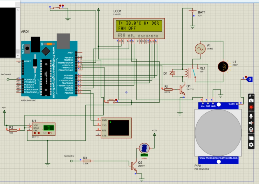
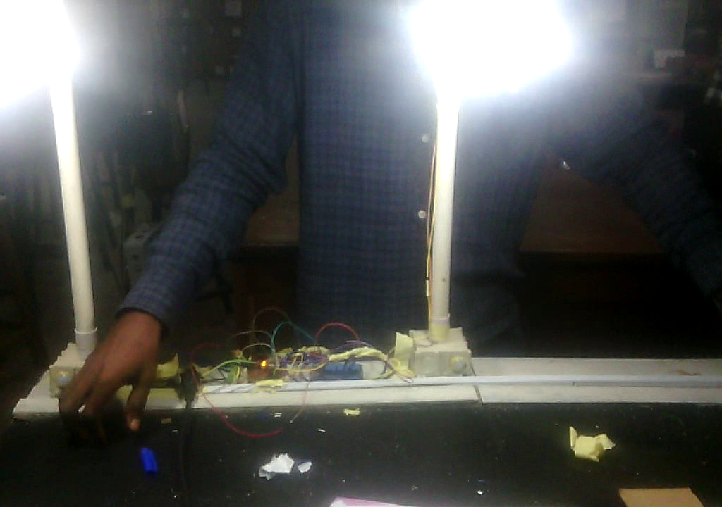
    To build a motion-activated light, you’ll need an Arduino board, a motion sensor module, and a relay module. The motion sensor module will detect motion and send a signal to the Arduino board. The Arduino board will then activate the relay module, which will turn on the light.

    Light-Activated Lights

    Another popular Arduino smart light control project is the light-activated light. This type of light automatically turns on when it gets dark, and turns off again when it gets light. Light-activated lights are great for outdoor lighting, as they can help to reduce energy consumption.

    Arduino smart light control project ideas

    To build a light-activated light, you’ll need an Arduino board, a light sensor module, and a relay module. The light sensor module will detect the ambient light level and send a signal to the Arduino board. The Arduino board will then activate the relay module, which will turn on the light when it gets dark.

    Smartphone-Controlled Lights

    Arduino can also be used to create smartphone-controlled lights. This type of light can be turned on and off remotely using a smartphone app. Smartphone-controlled lights are great for convenience and security.

    To build a smartphone-controlled light, you’ll need an Arduino board, a WiFi module, and a relay module. The WiFi module will allow the Arduino board to communicate with your smartphone. The relay module will turn on the light when it receives a signal from the Arduino board.

    Other Project Ideas

    Here are a few other Arduino smart light control project ideas:

    • Dimmable lights: Arduino can be used to create dimmable lights. This allows you to adjust the brightness of your lights to your liking.
    • RGB lights: Arduino can be used to create RGB lights. RGB lights can display any color of light, which makes them great for creating mood lighting or decorative lighting.
    • Music-reactive lights: Arduino can be used to create music-reactive lights. These lights change color and brightness in response to music, which can create a fun and festive atmosphere.

    Getting Started

    If you’re interested in building an Arduino smart light control project, there are a few things you’ll need to get started:

    • An Arduino board
    • A variety of sensors and modules, depending on the project you want to build
    • A relay module
    • Jumper wires
    • A soldering iron (optional)

    Once you have your supplies, you can start building your project. There are many tutorials and resources available online to help you get started.

    Conclusion

    Arduino smart light control projects are a great way to learn about Arduino and to add some automation and convenience to your home. With a little creativity, you can create a variety of different smart lighting projects that meet your specific needs.

    Read More

    FAQs

    Q: What is the most popular Arduino smart light control project?

    A: The most popular Arduino smart light control project is the motion-activated light. This is because motion-activated lights are simple to build and can be very useful for energy savings and security.

    Q: What are the benefits of using Arduino for smart light control?

    A: Arduino is a great platform for smart light control because it is relatively inexpensive and easy to use. Arduino also offers a wide range of sensors and modules that can be used to create a variety of different smart lighting projects.

    Q: What are some tips for building Arduino smart light control projects?

    A: Here are a few tips for building Arduino smart light control projects:

    • Start with a simple project and gradually work your way up to more complex projects.
    • Use a breadboard to prototype your circuit before soldering it together.
    • Test your circuit thoroughly before installing it in your home.
    • Use a good quality power supply to power your Arduino
    • What all projects can you make using an Arduino?
      • Arduino can be used for a wide range of projects, including but not limited to:
        • Home automation systems
        • Robotics projects
        • Weather stations
        • LED displays and lighting control
        • Smart mirrors
        • Security systems
        • IoT (Internet of Things) devices
    • How to make cool Arduino projects?
      • To make cool Arduino projects, start with simple ones and gradually increase complexity.
      • Use sensors, actuators, and modules to add functionality.
      • Explore online resources, tutorials, and project ideas for inspiration.
      • Join Arduino communities to learn from others and share your projects.
    • Which is better Arduino or Raspberry Pi?
      • Arduino and Raspberry Pi serve different purposes. Arduino is better for real-time control and simple tasks, while Raspberry Pi is a full-fledged computer suitable for more complex applications like running a web server or handling multimedia tasks.
    • How to control lights with Arduino?
      • Use a relay module to control high-voltage lights.
      • Connect the relay to Arduino and program it to switch the lights on/off based on conditions.
      • Alternatively, use an Arduino-compatible light sensor or motion sensor to control lights automatically.
    • What should be my first Arduino project?
      • A simple LED blinking project is a great start for beginners.
      • Move on to projects like a temperature sensor, basic robotics, or a simple home automation task to gain more experience.
    • Can Arduino connect to WiFi?
      • Yes, Arduino can connect to WiFi using WiFi modules like the ESP8266 or ESP32. These modules enable wireless communication and internet connectivity for Arduino projects.
    • Where is Arduino used in real life?
      • Arduino is used in various real-life applications, including:
        • Industrial automation
        • Medical devices
        • Automotive systems
        • Home automation
        • Education (for teaching electronics and programming)
    • What programming language does Arduino use?
      • Arduino uses a simplified version of C/C++ for programming. The Arduino IDE provides a user-friendly interface for writing and uploading code to the Arduino board.
    • Can we make robots using Arduino?
      • Yes, Arduino is commonly used in robotics projects. It can control motors, sensors, and other components necessary for building robots.
    • What is more powerful than Arduino?
      • Microcontrollers like Raspberry Pi, BeagleBone, or more advanced development boards like STM32 or ESP32 are generally more powerful than basic Arduino boards.
    • Which is better Python or Arduino?
      • Python and Arduino serve different purposes. Python is a high-level programming language suitable for various applications, while Arduino uses C/C++ and is more focused on embedded systems and physical computing.
    • Can Arduino run Python?
      • While Arduino itself doesn’t run Python directly, there are some projects and platforms that allow you to use Python with Arduino. For example, you can use a Raspberry Pi along with an Arduino, and the Raspberry Pi can run Python scripts while communicating with the Arduino for hardware control.
  • Design Weather-Based and Temperature Controlled Automatic Window

    Design Weather-Based and Temperature Controlled Automatic Window

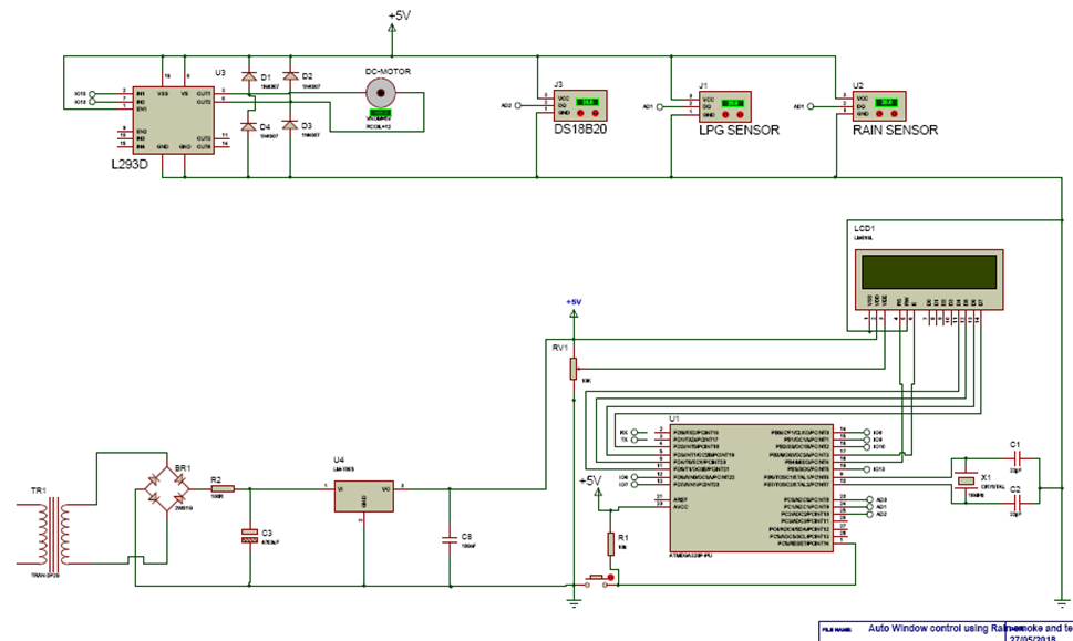
    The project design, weather-based and temperature automatic window involves the use of rain sensor, smoke sensor, temperature sensor module to control the automatic closing and opening of a window in a house (home) model through a DC motor. This project involves a microcontroller, the Atmega328P, which is used to process the various sensor signals received when they are connected to the microcontroller and The microcontroller controls the system motor. The motor is running on a 5V DC voltage supply and receives input control signals from the microcontroller through a motor driver module. The motor is an interface between the microcontroller and user-end windows and significantly simplifies power distribution. A Proteus IDE is used for the project design simulation, schematic capture and printed circuit board design

    How to design weather-based and temperature controlled automatic window
    Atmega328P-IC

    Weather-based and temperature-controlled Automatic Window: The Components Needed

    ComponentsQuantity
    5V DC Power Supply Module1
    DVD Motor Chassis1
    LCD 16021
    16MHz Crystal Oscillator1
    22pF capacitor2
    100nF capacitor2
    10K resistor4
    pushbutton2
    MQ2 Smoke sensor module1
    Rain sensor module1
    DS18B20 Temperature Sensor1
    Motor Driver module1
    3×6 Inch casing1
    LED indicator2
    Switch Button1
    Table of components

    The Schematic Diagram

    How to design weather-based and temperature controlled automatic window: The schematic diagram
    How to design weather-based and temperature controlled automatic window: The schematic diagram

    Explanation of the Schematic Diagram

    The power supply for the project design
    The power supply for the project design

    The power supply circuit used for this project is a regulated AC to DC linear power supply circuit. The AC voltage, typically 230 Vrms is connected to a transformer which steps down the 230V AC to 12V AC for rectification. The two wires of the primary side of the transformer will be connected to the socket outlet using a power cord. This AC voltage coming in from the step down transformer enters the bridge rectifier which is used to convert the ac supply to dc. The rectified voltage from the rectifier is a pulsating DC voltage having very high ripple content. But this is not what we want, we want a pure ripple free DC waveform. Hence a filter capacitor is used.

    The pulsating DC voltage which still contains some AC voltage flows to the capacitor which is used to smoothing the ripples from the rectifier output. The capacitors used here is 1000µF and 0.1 µF respectively. Two capacitors are used in the power supply unit; C1 and C2, to ensure that the ripple coming from the rectifier output is fully rectified by blocking any trace of AC that might have escaped the bridge rectifier during rectification. The positive side of the bridge rectifier is connected to the positive leg of the capacitor C1 while the negative side of the bridge rectifier is grounded. A voltage regulator is used in this circuit; LM7805 regulator. The LM7805 gives the output of 5V. The pin 1 of the voltage regulator is connected to the positive leg of C1 (1000µF), pin 2 is grounded and pin 3 is connected to the positive of another capacitor C2 (0.1µF).

    When the power from the mains is ON, current flows through the power supply circuit, the current that flows to the LM7805 regulator will give an output of 5V. The secondary side of the transformer is connected to the DC output of the bridge rectifier.

    How to design weather-based and temperature controlled automatic window: Connecting the temperature sensor to Atmega328P IC
    How to design a weather-based and temperature controlled automatic window: Connecting the temperature sensor to Atmega328P IC

    The DS1820 is connected as shown in the circuit diagram above. The DS18B20 digital thermometer provides 9-bit to 12-bit Celsius temperature measurements and has an alarm function with nonvolatile user-programmable upper and lower trigger points. The DS18B20 communicates over a 1-Wire bus that by definition requires only one data line (and ground) for communication with a central micro­processor. In addition, the DS18B20 can derive power directly from the data line (“parasite power”), eliminating the need for an external power supply. 

    How to design weather-based and temperature controlled automatic window: The control unit

    The control unit in the project design is the microcontroller which is used as the “Brain” of the design Project. The microcontroller will be used to execute the program given to it, which determines how the project will behave or work.

    WINDOW DRIVING UNIT

    This is the functioning output of the design, this consist of the stepper motor and motor driver, L293D, connected to the window. This is the mechanism used to open and close the window. The L293D motor driver acts as an interface between the stepper motor with the atmega328p-pu microcontroller. The L293D motor driver is used for rotating the motor in clockwise or anticlockwise direction. To drive the motor pin 1 or pin 9 has to be high. This are the Enable pins for driving the motor. The motor is connected on the output pins (pins 3, 6). The motors are rotated on the basis of the inputs provided across the input pins as LOGIC 0 or LOGIC 1. Pin 2 and Pin 7 are the input pin, this pins are used to regulate the rotation of the motor connected across pins 3 and pin 6. Pin 2 and Pin 7 are connected to the microcontroller to control the speed and direction of the motor. 5V power supply is given to the motor driver and the stepper motor. The motor driver is grounded at (pins 13, 12) and (pins 4, 5).
    • Pin 2 = Logic 1 and Pin 7 = Logic 0 | Clockwise Direction
    • Pin 2 = Logic 0 and Pin 7 = Logic 1 | Anticlockwise Direction
    • Pin 2 = Logic 0 and Pin 7 = Logic 0 | Idle [No rotation] [Hi-Impedance state]
    • Pin 2 = Logic 1 and Pin 7 = Logic 1 | Idle [No rotation].
    With the clockwise and anticlockwise movement of the motor, this set to open and close the window.

    Read More

    The Source Code

    /*
    /* PROGRAM TO USE RAIN SENSOR, SMOKE SENSOR AND TEMP SENSOR
     *  TO SENSE THE ENVIROMENT OF A SMART SYSTEM AND CLOSE AND OPEN
     *  A WINDOW
     */
     
     #include <LiquidCrystal.h>
    
    //include the oneWire lib 
    #include <OneWire.h>
    //include the Dallas temp lib
    #include <DallasTemperature.h>
    
    // Data wire is plugged into pin 2 on the Arduino
    #define ONE_WIRE_BUS A1
    
      int windowForward = 10;
      int windowBackward = 13;
     
    
    int switch1 = 6;
    int switch2 = 7;
    
    //State the toxidity level
     int toxicLevel = 350;
    
    // analog pin 0 = sensor  i/p
    int rainSensePin= A0; 
    
    // current counter - goes up by 1 every second while sensing
    int curCounter= 0; 
    
    //declear the i/p for smoke detection
    int smokeSense = A2;
    
    // Setup a oneWire instance to communicate with any OneWire devices connected 
    OneWire oneWire(ONE_WIRE_BUS);
     
    // Pass our oneWire reference to Dallas Temperature.
    DallasTemperature sensors(&oneWire);
    // initialize the library by associating any needed LCD interface pin
    //state which pin of the LCD is connected
    LiquidCrystal lcd(12, 11, 5, 4, 3, 2);
    
    void setup(){
      Serial.begin(9600);
      sensors.begin();
      pinMode(windowForward, OUTPUT);
      pinMode(windowBackward, OUTPUT);
      pinMode(switch1, INPUT);
      pinMode(switch2, INPUT);
      lcd.begin(16, 2);
      // Display a welcome message
      lcd.setCursor(0, 0);
      lcd.print("AUTOMATIC WINDOW"); 
      delay(500);
      lcd.setCursor(0, 1);
      lcd.print(" CONTROL SYSTEM: ");
      delay(2000);
      lcd.setCursor(0, 0);
      lcd.print("1> RAIN-SENSING,"); 
      delay(1500);
      lcd.setCursor(0, 1);
      lcd.print("2> TEMP-SENSING,");
      delay(1000);
      lcd.setCursor(0, 0);
      lcd.print("2> TEMP-SENSING,");
      delay(1000);
      lcd.setCursor(0, 1);
      lcd.print("3> SMOKE-SENSING");
      delay(2000);
      lcd.setCursor(0, 0);
      lcd.print("  DESIGNED BY:  ");
      delay(1000);
      lcd.setCursor(0, 1);
      lcd.print("OMOLOLA  ADEMOLA");
      delay(2000);
      }
    
    void loop(){
    sensors.requestTemperatures(); 
    Serial.print("  Temperature is: ");
    Serial.print(sensors.getTempCByIndex(0));
    Serial.println("'C");
    float roomTemp = sensors.getTempCByIndex(0);
      lcd.setCursor(0, 0);
      lcd.print("ROOM TEMP:");
      lcd.setCursor(9, 0);
      lcd.print(roomTemp);
      lcd.setCursor(14, 0);
      lcd.print("'C");
      
    
    int rainSenseReading = analogRead(rainSensePin); 
    Serial.print("NOw rain ");
    Serial.println(rainSenseReading);
                                               
    
    //begin reading from smoke sensor
    int readSmoke = analogRead(smokeSense);
    Serial.print(" Now Smokereading: ");
    Serial.println(readSmoke);
    delay(500);
    
      int sense1 = digitalRead(switch1);
      int sense2 = digitalRead(switch2);
      
       if( sense2 == LOW) {
       if ((rainSenseReading < 350) || (readSmoke >= 280)){ 
         digitalWrite(windowForward, HIGH);
        digitalWrite(windowBackward, LOW);
        delay(300);
        lcd.setCursor(0, 1);
        lcd.print("WINDOW      ");
        lcd.setCursor(7, 1);
        lcd.print("OPENED    ");
       }
       }
        else if( sense2 == HIGH){
        if ((rainSenseReading < 350) || (readSmoke >= 280)){
        digitalWrite(windowForward, LOW);
        digitalWrite(windowBackward, LOW);
        delay(300);
        
        }
         
       }
       
    
    if( sense1 == LOW) {
    if((roomTemp > 40.00) && (rainSenseReading > 350) && (readSmoke <= 280) )
    {
        digitalWrite(windowForward, LOW);
        digitalWrite(windowBackward, HIGH);
        delay(300);
        lcd.setCursor(0, 1);
        lcd.print("WINDOW      ");
        lcd.setCursor(8, 1);
        lcd.print("CLOSED    ");
        
      }
    }
    else if( sense1 == HIGH)
    {
      if((roomTemp > 40.00) && (rainSenseReading > 350) && (readSmoke <= 280))
      digitalWrite(windowForward, LOW);
      digitalWrite(windowBackward, LOW);
      delay(300);
    
    }
    }


    Conclusion

    The project design was constructed and programmed following the circuit diagram and program codes shown here and it worked as expected. The house model has a window that closes automatically when there is a rain dropping at the top of the roof.

  • Anti-Loss & Item Location Device Using Arduino and Bluetooth App

    Anti-Loss & Item Location Device Using Arduino and Bluetooth App

    This project design, Anti-Loss And Item Location Device, implements a Bluetooth tracking tag-sized device that is attached user’s items as against losing them or misplacing them.  The tracking system uses an android based platform app that is connected via Bluetooth to the smart tag tracker. The Bluetooth tracker was designed to have both an in-range notification and an out-range notification to signal the user about the proximity status of his/her belongings. It provides users a button on the Android screen that can be pressed, which makes the portable tag-sized tracker give out a notification beep that users can follow to ascertain the exact location of the item. The design was constructed to save power and ensure its durability by making use of a replaceable battery and relies on the phone to do all the ‘heavy lifting’ when it comes to data transmission in Bluetooth mode.

    Anti-Loss And Item Location Device: The Android app
    Anti-Loss And Item Location Device: The Android app

    Anti-Loss And Item Location Device: The Components Needed

    ComponentsQuantity
    9V Battery1
    LM7805 5V regulator IC1
    Pushbutton1
    10K, 1K resistors3
    LED2
    Atmega328P IC1
    16MHz Crystal1
    NPN resistor1
    piezo buzzer1
    Bluetooth module HC-051
    Dc SPST switch1

    Anti-Loss And Item Location Device: The Circuit Diagram

    Circuit diagram of Anti-Loss And Item Location Device
    Circuit diagram of Anti-Loss And Item Location Device

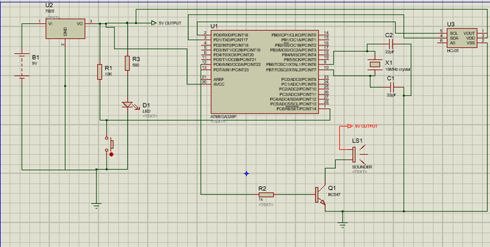
    The circuit diagram shown above shows how the Atmega328P IC is connected to the Bluetooth module and other peripherals in the project to make up the design. We connected both the Bluetooth module and the Atmega328P IC to the 5V output from the voltage regulator LM7805.

    Setting Up And Designing the Android App On MIT AppInventor

    The app was created using the MIT App Inventor. Below is a snippet of the block codes.

    Anti-Loss And Item Location Device; creating the app online
    Anti-Loss And Item Location Device; creating the app online

    In the app called Ibukun_mark2, our goal was to make the app auto reconnect, that way we can always detect when the app disconnects. And prompt it to notify us and also program it to automatically reconnect when within connection range. The easiest way would be to input the HC-05 address in the screen1.initialize block such that if the Bluetoothclient1 calls that address on startup, it can connect on its own. Then add notifier to shows us successful connection.But this would only limit us to using only one Bluetooth module. This isn’very practical so we had to invent another method. We wanted an app that when we click the bluetooth (BT) button to bring up a list of paired devices. We select one of the paired devices, in my case the HC-05. And If the connection is successful the BT button changes to “Connected”; plays a tone. Leaving us the address of the connected BT device is displayed on screen. Plays another tone when disconnected and autoreconnects when within the paired Bluetooth device range. There are only a few screen elements to note:

    • A button to activate the connection process.
    • A label to show the saved address.
    • The non-visible components required are:
      • TinyDB.
      • Clock1.
      • And of course the Bluetooth client.

    We started by initializing a global variable which we can call back at any time during our coding.

    The app code

    The complete .AIA file can be download here for free. You can make some changes on your own if you like.

    The completed app
    The completed app

    Anti-Loss And Item Location Device: The Arduino Source Code

    boolean debug = true;
     
    #include <SoftwareSerial.h>
    SoftwareSerial BTserial(0,1); // RX | TX
    // Connect the HC-06 TX to the Arduino RX. 
    // Connect the HC-06 RX to the Arduino TX through a voltage divider.
     
    // max length of command is 20 chrs
    const byte numChars = 20;
    char receivedChars[numChars];
    boolean newData = false;
    
    int piezoPin = 6; 
    byte ledPin = 12;              
    byte names[] = {'c', 'd', 'e', 'f', 'g', 'a', 'b', 'C'};  
    int tones[] = {1915, 1700, 1519, 1432, 1275, 1136, 1014, 956};
    byte melody[] = "2d2a1f2c2d2a2d2c2f2d2a2c2d2a1f2c2d2a2a2g2p8p8p8p";
    // count length: 1 2 3 4 5 6 7 8 9 0 1 2 3 4 5 6 7 8 9 0 1 2 3 4 5 6 7 8 9 0
    //                                10                  20                  30
    int count = 0;
    int count2 = 0;
    int count3 = 0;
    int MAX_COUNT = 24;
    int statePin = LOW;


    void piezoTone() {
      analogWrite(piezoPin, 0);     
      for (count = 0; count < MAX_COUNT; count++) {
        statePin = !statePin;
        digitalWrite(ledPin, statePin);
        for (count3 = 0; count3 <= (melody[count*2] - 48) * 30; count3++) {
          for (count2=0;count2<8;count2++) {
            if (names[count2] == melody[count*2 + 1]) {       
              analogWrite(piezoPin,500);
              delayMicroseconds(tones[count2]);
              analogWrite(piezoPin, 0);
              delayMicroseconds(tones[count2]);
            } 
            if (melody[count*2 + 1] == 'p') {
              // make a pause of a certain size
              analogWrite(piezoPin, 0);
              delayMicroseconds(500);
            }
          }
        }
      }
    }
     
    void setup() 
    {
         pinMode(ledPin, OUTPUT); 
          pinMode(piezoPin, OUTPUT); 
         Serial.begin(9600);
         Serial.println("<Arduino is ready>");
     
         // The default baud rate for the HC-06s I have is 9600. Other modules may have a different speed. 38400 is common.
         BTserial.begin(9600); 
    }
     
    void loop() 
    {
         if (BTserial.available() > 0)     {  recvWithStartEndMarkers(); }
         if (newData) { parseData(); }
    }     
     
     
    void parseData()
    {  
            newData = false;    
            if (debug) {  Serial.println( receivedChars ); }
            if (receivedChars[0] == 'O'  && receivedChars[1] == 'N' )  {
              piezoTone();
              }
            if (receivedChars[0] == 'O'  && receivedChars[1] == 'F' )  { 
              digitalWrite(ledPin,LOW);   }       
    }
     
     
    void recvWithStartEndMarkers() 
    {
     
         // function recvWithStartEndMarkers by Robin2 of the Arduino forums
         // See  http://forum.arduino.cc/index.php?topic=288234.0
     
         static boolean recvInProgress = false;
         static byte ndx = 0;
         char startMarker = '<';
         char endMarker = '>';
         char rc;
     
         if (BTserial.available() > 0) 
         {
              rc = BTserial.read();
              if (recvInProgress == true) 
              {
                   if (rc != endMarker) 
                   {
                        receivedChars[ndx] = rc;
                        ndx++;
                        if (ndx >= numChars) { ndx = numChars - 1; }
                   }
                   else 
                   {
                         receivedChars[ndx] = '\0'; // terminate the string
                         recvInProgress = false;
                         ndx = 0;
                         newData = true;
                   }
              }
     
              else if (rc == startMarker) { recvInProgress = true; }
         }
    }
    

    Conclusion

    The project design did very well when used and it worked for us. Let us know if you used this blog post as a guide to build your own project in the comment section below.

    Read More

  • How to Design A Solar Tracker Robot With Arduino

    How to Design A Solar Tracker Robot With Arduino

    This blog post details the design and construction of a uniaxial solar tracker that would follow the direction of the sun, ensuring maximum harvest of the solar panel. Most homes face the problem of peak harvest of sunlight. This project design would help reduce this challenge.

    Components Needed For Solar Tracker Project Design

    ITEM DESCRIPTIONQUANTITY
    VOLTAGE REGULATOR1
    LDR2
    TRANSFORMER1
    LEDs1
    RESISTORS, 10K and 1K6
    ATMEGA328P1
    CONNECTING WIRES3YARD
    CASING1
    VERO BOARD2
    Bridge Rectifier1
    16MHz Crystal Oscillator1
    1000uF electrolytic Capacitor3
    SOLDERING IRON1
    BREAD BOARD3
    CAPACITOR4
    1A FUSE1
    VARISTOR1
    0.01uF Capacitor1
    Pushbutton1
    Servo Motor MG9901
    22pF Capacitor2
    MISCELLANEOUS5
    Table of components list for the project design

    Solar Tracker Robot: The Circuit Diagram

    Solar Tracker Robot: The circuit diagram
    Solar Tracker Robot: The circuit diagram

    Explanation for Circuit Diagram of Solar Tracker Robot

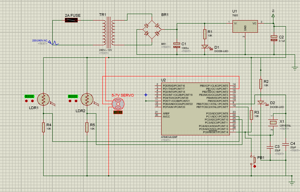
    The schematic diagram shown above was done with Proteus IDE, It used two Light Dependent Resistors (LDRs) to sense and measure the average amount of sun intensity, hence move the solar panel to the direction of the sun. The LDR is connected in series with a 10K resistor. This forms a voltage divider and we can use the program code to do a bit of calculations to determine where best to position the solar panel.

    The project design doesn’t use an Arduino board but a standalone version. The brain of the project is the Atmega328P IC. It is powered by the 5V power supply circuit that is shown above. This is a linear power supply circuit diagram; one can also opt for an already made power supply unit.

    The Arduino Source Code

    #include <Servo.h> 
     
    Servo tracker;  // create servo object to control a servo 
    int eastLDRPin = 0;  //Assign analogue pins
    int westLDRPin = 1;
    int eastLDR = 0;   //Create variables for the east and west sensor values
    int westLDR = 0;
    int error = 0;
    int calibration = 10;  //Calibration offset to set error to zero when both sensors receive an equal amount of light
    int trackerPos = 90;    //Create a variable to store the servo position
    
    void setup() 
    { 
      tracker.attach(9);  // attaches the servo on pin 11 to the servo object
      Serial.begin(9600);
       tracker.write(90);
       delay(5000);
    } 
     
     
    void loop() 
    { 
      eastLDR = calibration + analogRead(eastLDRPin);    //Read the value of each of the east and west sensors
      westLDR = analogRead(westLDRPin);
      error = eastLDR - westLDR;          //Determine the difference between the two sensors.
      if(error>15)        //If the error is positive and greater than 15 then move the tracker in the east direction
      {
       
        tracker.write(180);              // tell servo to go to position in variable 'pos' 
        delay(500);                       // waits 15ms for the servo to reach the position 
      
      }
     else if(error<-15)  //If the error is negative and less than -15 then move the tracker in the west direction
      {
                       
        tracker.write(0);              // tell servo to go to position in variable 'pos' 
        delay(500);                       // waits 15ms for the servo to reach the position 
       }
             
      Serial.print(eastLDR);
      Serial.print("   ");
      Serial.print(westLDR);
      Serial.print("   ");
      Serial.println(error);
      delay(500);
    }


    Conclusion

    Solar trackers are important because they can significantly increase the energy output of solar panels. By tracking the sun’s movement across the sky, solar trackers ensure that the panels are always perpendicular to the sun’s rays, which allows them to capture the most sunlight possible. This can increase energy production by up to 40%, depending on the location and climate

    Read More

  • IoT Generator Monitoring Using Arduino and RemoteXY

    IoT Generator Monitoring Using Arduino and RemoteXY

    This blog post, Generator Monitoring using Arduino and RemoteXY is about remote monitoring of generator over Wi-Fi system. The project design can measure the output AC voltage level of a generator, the temperature of the generator, to show it is overheating or not and also monitor and detect the feul level in the generator tank. All of these measured parameters will be displayed on the remote dashboard that can be accessed on an Android app of RemoteXY.

    Generator Monitoring using Arduino and RemoteXY: The type of step-down transformer used
    Generator Monitoring using Arduino and RemoteXY: The type of step-down transformer used

    The project design is therefore divided into four units; the power supply unit (PSU), the Voltage Sensor Unit, the Temperature sensing unit and the fuel level detection unit. The power supply gives 5V DC to the project design. The voltage senor unit does the AC voltage measurements, whereas the temperature sensing unit senses the temperature of the generator and the feul level tells us the volume of the feul in the tank.

    Components Needed For this Project Design

    ComponentsQuantity
    DS18B20 sensor1
    Arduino Voltage sensor1
    22K and 4.7K resistors1 each
    Ultrasonic sensor HC-SR041
    5V Zener Diode1
    12V AC step-down transformer1
    bridge rectifier1
    50uF 50V electrolytic capacitor1
    Atmega328P IC1
    100nF capacitor1
    LM7805 IC1
    Switch 1A1
    22K Resistor1
    ESP8266-01 Module1
    22pF capacitors2
    16MHz Crystal1
    Female header pin2 sets
    Male header pins2 sets
    Connector and wires5 yards
    Casing3×6 inch size

    Circuit Diagram for Generator Monitoring using Arduino and RemoteXY

    Generator Monitoring using Arduino and RemoteXY: The Circuit Diagram
    Generator Monitoring using Arduino and RemoteXY: The Circuit Diagram

    Explanation of the Circuit Diagram

    The schematic diagram was designed using Proteus IDE, the schematic diagram begins with the connection of the step-down transformer to the AC mains. The step-down transformer give out 12V AC which is rectified by the bridge rectifier. There is a filter capacitor for AC ripples and a 5V regulator LM7805 IC, to produce 5V DC. This is further rectified by the 470uF and 100uF capacitors before connecting it to a pulldown resistor to the IO pin of the Atmega328P IC. This will work with the program that will tell us when the pushbutton is pressed.

    Generator Monitoring using Arduino and RemoteXY: The Circuit Diagram for voltage sensor unit
    Generator Monitoring using Arduino and RemoteXY: The Circuit Diagram for voltage sensor unit

    The Atmega328P IC is powered by the 5V output from the power supply. Hence its connection to the power rails. The Atmega328P IC is also responsible for measuring the amplitude of AC voltage by using a voltage divider principle of the resistors connected in series. As well as use a serial communication protocol to communicate with the ESP-01 module.

    Atmega328P IC
    Atmega328P IC

    Also, the Voltage Sensor was taken from the power supply unit; by using the principle of Voltage Divider law (VDL). But also keeping at heart that the maximum current to any analogue pin of the microcontroller shouldn’t exceed 150mA (!≥ 150mA). To get 5V, having a 30.5KΩ known resistor in series with   unknown resistor, the value of the unknown resistor was calculated as:

    Voltage divider law

    The Temperature Sensor Unit

    Temperature sensor unit

    This IC which is also the brain of the project measure the temperature of the DS18B20 sensor.

    Generator Monitoring using Arduino and RemoteXY: The Circuit Diagram

    The power supply unit circuit is specifically designed as shown above. This circuit diagram is an excerpt of the complete design shown above. We brought this out just to show the stepdown process, the rectification process, the filtration process and the voltage regulation process. And a good design is further done when one can add an indictor that the power supply can output 5V by adding an LED indicator as shown in the circuit above.

    Designing the RemoteXY App for Remote Monitoring

    The designing of the RemoteXY app is pretty straight forward. Just go to the Remotexy website and log in after signing up. Read how to setup your dashboard on this HOW TO BUILD A WiFi BASED SMART FARM and read Smart Android System for more.

    Programming Generator Monitoring using Arduino and RemoteXY Project

    #include <DallasTemperature.h>
    
    #include <OneWire.h>
    
    //state where the input of the temp sensor is connected
    #define ONE_WIRE_BUS A0 
    
      int echoPin = 9;
      int trigPin = 10;
      long duration, cm, inches;
     
    //set the OneWire lib to comm with other bus
    OneWire oneWire(ONE_WIRE_BUS);
    //transfer the data to Dallas temp Lib
    DallasTemperature sensors(&oneWire);
    
    // RemoteXY select connection mode and include library 
    #define REMOTEXY_MODE__ESP8266_HARDSERIAL_POINT
    
    #include <RemoteXY.h>
    
    // RemoteXY connection settings 
    #define REMOTEXY_SERIAL Serial
    #define REMOTEXY_SERIAL_SPEED 115200
    #define REMOTEXY_WIFI_SSID "ANSA_GEN_MONITOR"
    #define REMOTEXY_WIFI_PASSWORD "9876543210"
    #define REMOTEXY_SERVER_PORT 6377
    
    
    // RemoteXY configurate  
    #pragma pack(push, 1)
    uint8_t RemoteXY_CONF[] =
      { 255,0,0,248,1,63,0,8,61,0,
      129,0,1,8,97,9,16,65,78,83,
      65,95,71,69,78,95,77,79,78,73,
      84,79,82,0,67,0,2,36,97,7,
      16,26,101,67,0,37,36,62,7,16,
      26,101,67,0,67,36,32,7,16,26,
      101,67,0,1,29,97,9,16,26,201 };
      
    // this structure defines all the variables of your control interface 
    struct {
    
        // output variable
      char VOLT[101];  // string UTF8 end zero 
      char FUEL[101];  // string UTF8 end zero 
      char TEMP[101];  // string UTF8 end zero 
      char TEXT[201];  // string UTF8 end zero 
    
        // other variable
      uint8_t connect_flag;  // =1 if wire connected, else =0 
    
    } RemoteXY;
    #pragma pack(pop)
    
    /////////////////////////////////////////////
    //           END RemoteXY include          //
    /////////////////////////////////////////////
    
    
    //declear the voltage initial state
    float Vout = 0.0;
    float  Vin = 0.0;
    //declear the resistors used in VDL of Voltage sensor 
    float R1 = 9820.0;
    float R2 = 2150.0;
    
    void setup() 
    {
      RemoteXY_Init (); 
    
     //begin the temp sensor
      sensors.begin();
     
      //outline the inputs and output pins
    
      pinMode(trigPin, OUTPUT);
      pinMode(echoPin, INPUT);
      
    }
    
    void loop() 
    { 
      RemoteXY_Handler ();
      sprintf (RemoteXY.TEXT, "GEN_VOLTAGE (V):            FUEL (Litres):              GEN_TEMP ('C):");
      double sense = analogRead(A1);
      double Vout = (sense * 5.0)/1023.0;
      double Vin = Vout /(R2/(R1+R2));
      double voltage = (Vin + 1.1) * 16.0;
      int AC = voltage;
     dtostrf(voltage, 0, 2, RemoteXY.VOLT);
    
       //trigger the U sensor
      digitalWrite(trigPin, LOW);
      delay(5);
      digitalWrite(trigPin, HIGH);
      delay(10);
      digitalWrite(trigPin, LOW);
      //ask the U sensor to start measuring dist
      duration= pulseIn(echoPin, HIGH);
      //get the dist in cm by dividing 148 ie how
      //how long it takes the U sender to send 
      //and received by its receiver
      cm = duration/58;
      double r = 9.00;
      double rubber = 3.142* ((r) * (r) * cm);
      double litre = rubber/1000.00;
      dtostrf(litre, 0, 2, RemoteXY.FUEL);
    
    
      sensors.requestTemperatures();
      float Temp = sensors.getTempCByIndex(0);
      dtostrf(Temp, 0, 2, RemoteXY.TEMP);
    
      delay(500);
    }
    

    Testing and Results

    Generator Remote Monitoring System design

    The Generator Remote Monitoring System is shown above. It has been encased and in the 3×6 inch pattress box. And The Ultrasonic sensor is brought outside as well as the temperature sensor. These are to be afixed at specific spots on the generator body. Namely, on top of the generator feul tank and the body of the generator. However we tested it at a feul level when the tank is almost empty.

    Generator Remote Monitoring System design; The RemoteXY view
    Generator Remote Monitoring System design; The RemoteXY view

    When the design is powered on, after ensuring the phone device is connected to the WiFi network created by the device. We opened the RemoteXY app and checked the device monitor. The result was shown above. We had a voltage level of 234V and a temperature of 29.31 degree Celsius. The feul level was 0 and this was expected since the tank was almost drained.

    Conclusion

    The Generator Remote Monitoring System project design has been designed and tested to be working as programmed. We will like to know if you performed the same process by following the steps mentioned in this blog post. Let us know in the comments below.