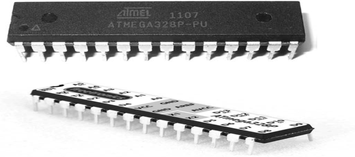
The project design, weather-based and temperature automatic window involves the use of rain sensor, smoke sensor, temperature sensor module to control the automatic closing and opening of a window in a house (home) model through a DC motor. This project involves a microcontroller, the Atmega328P, which is used to process the various sensor signals received when they are connected to the microcontroller and The microcontroller controls the system motor. The motor is running on a 5V DC voltage supply and receives input control signals from the microcontroller through a motor driver module. The motor is an interface between the microcontroller and user-end windows and significantly simplifies power distribution. A Proteus IDE is used for the project design simulation, schematic capture and printed circuit board design
Weather-based and temperature-controlled Automatic Window: The Components Needed
| Components | Quantity |
|---|---|
| 5V DC Power Supply Module | 1 |
| DVD Motor Chassis | 1 |
| LCD 1602 | 1 |
| 16MHz Crystal Oscillator | 1 |
| 22pF capacitor | 2 |
| 100nF capacitor | 2 |
| 10K resistor | 4 |
| pushbutton | 2 |
| MQ2 Smoke sensor module | 1 |
| Rain sensor module | 1 |
| DS18B20 Temperature Sensor | 1 |
| Motor Driver module | 1 |
| 3×6 Inch casing | 1 |
| LED indicator | 2 |
| Switch Button | 1 |
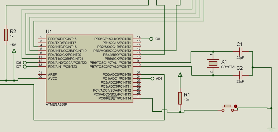
The Schematic Diagram
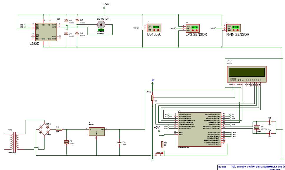
Explanation of the Schematic Diagram
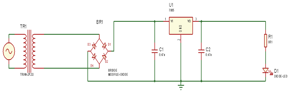
The power supply circuit used for this project is a regulated AC to DC linear power supply circuit. The AC voltage, typically 230 Vrms is connected to a transformer which steps down the 230V AC to 12V AC for rectification. The two wires of the primary side of the transformer will be connected to the socket outlet using a power cord. This AC voltage coming in from the step down transformer enters the bridge rectifier which is used to convert the ac supply to dc. The rectified voltage from the rectifier is a pulsating DC voltage having very high ripple content. But this is not what we want, we want a pure ripple free DC waveform. Hence a filter capacitor is used.
The pulsating DC voltage which still contains some AC voltage flows to the capacitor which is used to smoothing the ripples from the rectifier output. The capacitors used here is 1000µF and 0.1 µF respectively. Two capacitors are used in the power supply unit; C1 and C2, to ensure that the ripple coming from the rectifier output is fully rectified by blocking any trace of AC that might have escaped the bridge rectifier during rectification. The positive side of the bridge rectifier is connected to the positive leg of the capacitor C1 while the negative side of the bridge rectifier is grounded. A voltage regulator is used in this circuit; LM7805 regulator. The LM7805 gives the output of 5V. The pin 1 of the voltage regulator is connected to the positive leg of C1 (1000µF), pin 2 is grounded and pin 3 is connected to the positive of another capacitor C2 (0.1µF).
When the power from the mains is ON, current flows through the power supply circuit, the current that flows to the LM7805 regulator will give an output of 5V. The secondary side of the transformer is connected to the DC output of the bridge rectifier.
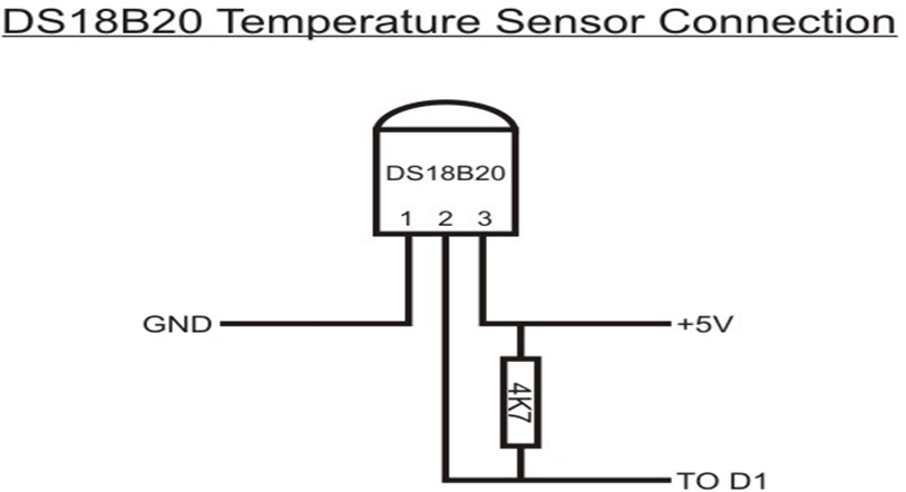
The DS1820 is connected as shown in the circuit diagram above. The DS18B20 digital thermometer provides 9-bit to 12-bit Celsius temperature measurements and has an alarm function with nonvolatile user-programmable upper and lower trigger points. The DS18B20 communicates over a 1-Wire bus that by definition requires only one data line (and ground) for communication with a central microprocessor. In addition, the DS18B20 can derive power directly from the data line (“parasite power”), eliminating the need for an external power supply.
The control unit in the project design is the microcontroller which is used as the “Brain” of the design Project. The microcontroller will be used to execute the program given to it, which determines how the project will behave or work.
WINDOW DRIVING UNIT
This is the functioning output of the design, this consist of the stepper motor and motor driver, L293D, connected to the window. This is the mechanism used to open and close the window. The L293D motor driver acts as an interface between the stepper motor with the atmega328p-pu microcontroller. The L293D motor driver is used for rotating the motor in clockwise or anticlockwise direction. To drive the motor pin 1 or pin 9 has to be high. This are the Enable pins for driving the motor. The motor is connected on the output pins (pins 3, 6). The motors are rotated on the basis of the inputs provided across the input pins as LOGIC 0 or LOGIC 1. Pin 2 and Pin 7 are the input pin, this pins are used to regulate the rotation of the motor connected across pins 3 and pin 6. Pin 2 and Pin 7 are connected to the microcontroller to control the speed and direction of the motor. 5V power supply is given to the motor driver and the stepper motor. The motor driver is grounded at (pins 13, 12) and (pins 4, 5).
• Pin 2 = Logic 1 and Pin 7 = Logic 0 | Clockwise Direction
• Pin 2 = Logic 0 and Pin 7 = Logic 1 | Anticlockwise Direction
• Pin 2 = Logic 0 and Pin 7 = Logic 0 | Idle [No rotation] [Hi-Impedance state]
• Pin 2 = Logic 1 and Pin 7 = Logic 1 | Idle [No rotation].
With the clockwise and anticlockwise movement of the motor, this set to open and close the window.
Read More
- How to Design Fire Detection And Video Surveillance Project
- IoT Based Carbon Monoxide and Carbon Dioxide Monitoring Device
- IoT Generator Monitoring Using Arduino and RemoteXY
The Source Code
/*
/* PROGRAM TO USE RAIN SENSOR, SMOKE SENSOR AND TEMP SENSOR
 *  TO SENSE THE ENVIROMENT OF A SMART SYSTEM AND CLOSE AND OPEN
 *  A WINDOW
 */

 #include <LiquidCrystal.h>

//include the oneWire lib
#include <OneWire.h>
//include the Dallas temp lib
#include <DallasTemperature.h>

// Data wire is plugged into pin 2 on the Arduino
#define ONE_WIRE_BUS A1

  int windowForward = 10;
  int windowBackward = 13;


int switch1 = 6;
int switch2 = 7;

//State the toxidity level
 int toxicLevel = 350;

// analog pin 0 = sensor  i/p
int rainSensePin= A0;

// current counter - goes up by 1 every second while sensing
int curCounter= 0;

//declear the i/p for smoke detection
int smokeSense = A2;

// Setup a oneWire instance to communicate with any OneWire devices connected
OneWire oneWire(ONE_WIRE_BUS);

// Pass our oneWire reference to Dallas Temperature.
DallasTemperature sensors(&oneWire);
// initialize the library by associating any needed LCD interface pin
//state which pin of the LCD is connected
LiquidCrystal lcd(12, 11, 5, 4, 3, 2);

void setup(){
  Serial.begin(9600);
  sensors.begin();
  pinMode(windowForward, OUTPUT);
  pinMode(windowBackward, OUTPUT);
  pinMode(switch1, INPUT);
  pinMode(switch2, INPUT);
  lcd.begin(16, 2);
  // Display a welcome message
  lcd.setCursor(0, 0);
  lcd.print("AUTOMATIC WINDOW");
  delay(500);
  lcd.setCursor(0, 1);
  lcd.print(" CONTROL SYSTEM: ");
  delay(2000);
  lcd.setCursor(0, 0);
  lcd.print("1> RAIN-SENSING,");
  delay(1500);
  lcd.setCursor(0, 1);
  lcd.print("2> TEMP-SENSING,");
  delay(1000);
  lcd.setCursor(0, 0);
  lcd.print("2> TEMP-SENSING,");
  delay(1000);
  lcd.setCursor(0, 1);
  lcd.print("3> SMOKE-SENSING");
  delay(2000);
  lcd.setCursor(0, 0);
  lcd.print("  DESIGNED BY:  ");
  delay(1000);
  lcd.setCursor(0, 1);
  lcd.print("OMOLOLA  ADEMOLA");
  delay(2000);
  }

void loop(){
sensors.requestTemperatures();
Serial.print("  Temperature is: ");
Serial.print(sensors.getTempCByIndex(0));
Serial.println("'C");
float roomTemp = sensors.getTempCByIndex(0);
  lcd.setCursor(0, 0);
  lcd.print("ROOM TEMP:");
  lcd.setCursor(9, 0);
  lcd.print(roomTemp);
  lcd.setCursor(14, 0);
  lcd.print("'C");


int rainSenseReading = analogRead(rainSensePin);
Serial.print("NOw rain ");
Serial.println(rainSenseReading);


//begin reading from smoke sensor
int readSmoke = analogRead(smokeSense);
Serial.print(" Now Smokereading: ");
Serial.println(readSmoke);
delay(500);

  int sense1 = digitalRead(switch1);
  int sense2 = digitalRead(switch2);

   if( sense2 == LOW) {
   if ((rainSenseReading < 350) || (readSmoke >= 280)){
     digitalWrite(windowForward, HIGH);
    digitalWrite(windowBackward, LOW);
    delay(300);
    lcd.setCursor(0, 1);
    lcd.print("WINDOW      ");
    lcd.setCursor(7, 1);
    lcd.print("OPENED    ");
   }
   }
    else if( sense2 == HIGH){
    if ((rainSenseReading < 350) || (readSmoke >= 280)){
    digitalWrite(windowForward, LOW);
    digitalWrite(windowBackward, LOW);
    delay(300);

    }

   }


if( sense1 == LOW) {
if((roomTemp > 40.00) && (rainSenseReading > 350) && (readSmoke <= 280) )
{
    digitalWrite(windowForward, LOW);
    digitalWrite(windowBackward, HIGH);
    delay(300);
    lcd.setCursor(0, 1);
    lcd.print("WINDOW      ");
    lcd.setCursor(8, 1);
    lcd.print("CLOSED    ");

  }
}
else if( sense1 == HIGH)
{
  if((roomTemp > 40.00) && (rainSenseReading > 350) && (readSmoke <= 280))
  digitalWrite(windowForward, LOW);
  digitalWrite(windowBackward, LOW);
  delay(300);

}
}
Conclusion
The project design was constructed and programmed following the circuit diagram and program codes shown here and it worked as expected. The house model has a window that closes automatically when there is a rain dropping at the top of the roof.

