Introduction
Managing chronic health conditions like diabetes and cardiovascular disease requires regular monitoring of vital health parameters. Traditional methods often involve invasive and uncomfortable procedures, which can be a significant burden for patients. However, advancements in technology have led to the development of non-invasive glucose and ECG levels monitoring systems. In this blog post, we will design and construct, as well as enable a non-invasive monitoring of glucose and ECG levels, using Arduino and some other modules thereby revolutionizing health tracking.
Advantages of Non-Invasive Methods over Traditional Methods
Non-invasive methods for glucose and ECG monitoring offer several advantages over traditional methods, including:
Glucose Monitoring:
- Pain-free: No more finger pricking or blood draws.
- Reduced risk of infection: Minimizes the risk of infection and other complications associated with invasive methods.
- Increased convenience: Easy to use and integrate into daily life.
- Improved user experience: Less discomfort and anxiety.
- Continuous monitoring: Enables real-time tracking of glucose levels.
- Early detection: Allows for early detection of glucose fluctuations.
- Personalized insights: Provides detailed information for personalized diabetes management.
ECG Monitoring:
- Convenience: Easy to use and integrate into daily life.
- Comfort: No more cumbersome electrodes or lead systems.
- Increased accuracy: Reduces signal interference and artifacts.
- Real-time monitoring: Enables continuous tracking of heart activity.
- Early detection: Allows for early detection of cardiac abnormalities.
- Improved diagnosis: Enhances diagnostic accuracy and confidence.
- Remote monitoring: Enables remote monitoring and telemedicine capabilities.
Shared Advantages:
- Cost-effective: Reduces costs associated with invasive methods.
- Increased compliance: Improves user adherence to monitoring regimens.
- Enhanced data analysis: Provides detailed insights for data-driven healthcare decisions.
- Reduced healthcare burden: Minimizes the burden on healthcare systems.
- Improved patient outcomes: Leads to better health outcomes and quality of life.
By leveraging non-invasive methods, individuals can take greater control of their health, and healthcare providers can make more informed decisions, ultimately leading to improved patient outcomes.
Arduino’s Role in DIY Health Monitoring Projects
Arduino is an popular open-source microcontroller platform, has revolutionized the DIY health monitoring landscape. Its ease of use, affordability, and versatility have made it an ideal choice for health enthusiasts, makers, and researchers. Here’s how Arduino is shaping DIY health monitoring projects:
- Accessibility: Arduino’s affordability and ease of use have democratized access to health monitoring technology, enabling individuals to create custom solutions.
- Customization: Arduino’s flexibility allows users to tailor health monitoring projects to specific needs, such as tracking glucose levels, heart rate, or respiratory patterns.
- Prototyping: Arduino’s rapid prototyping capabilities enable quick testing and iteration of ideas, accelerating the development of innovative health monitoring solutions.
- Community support: Arduino’s vast community provides extensive resources, libraries, and tutorials, facilitating collaboration and knowledge sharing among DIY health monitoring enthusiasts.
- Integration: Arduino can seamlessly integrate with various sensors, actuators, and communication modules, enabling the creation of comprehensive health monitoring systems.
Non-Invasive Glucose Level Monitoring
Over the years, several non-invasive technologies have emerged, including:
- Optical Sensors: Utilize infrared, near-infrared, and Raman spectroscopy to measure glucose levels.
- Electromagnetic Sensors: Employ radiofrequency and microwave sensing to detect glucose levels.
- Thermal Sensors: Measure the thermal properties of the skin to estimate glucose levels.
- Enzyme-Based Sensors: Use enzymes to break down glucose and measure the resulting electrical signal.
Each technology has its unique principle of operation. Optical sensors, for example, measure the absorption of light by glucose molecules in the skin. Electromagnetic sensors detect changes in the electrical properties of the skin caused by glucose fluctuations.
While non-invasive glucose monitoring systems have shown promising results, their accuracy and reliability are still being refined. Clinical trials and regulatory approvals are ongoing to ensure the safety and efficacy of these devices. Several non-invasive glucose monitoring devices are already available in the market, products like:
- GlucoTrack: A non-invasive glucose monitoring device using optical sensors.
- Dexcom G5: A mobile continuous glucose monitoring system.
Non-Invasive ECG Level Monitoring
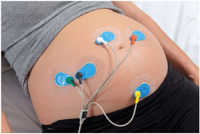
Traditional ECG monitoring methods involve electrodes and lead systems, which can be cumbersome and uncomfortable. Non-invasive ECG monitoring offers a convenient and comfortable alternative. Several non-invasive ECG monitoring technologies have emerged, including:
- Electrodes and Lead Systems: Use dry electrodes and wearable devices to measure ECG signals.
- Wearable Devices: Utilize smartwatches and fitness trackers to monitor ECG levels.
- Mobile ECG Devices: Offer portable and user-friendly ECG monitoring.
Non-invasive ECG monitoring technologies detect the electrical activity of the heart using dry electrodes or wearable devices.
Accuracy and Reliability
Non-invasive ECG monitoring systems have demonstrated high accuracy and reliability in detecting various heart conditions.
Devices and Products
Several non-invasive ECG monitoring devices are already available, including, Apple Watch Series 4 that offers built-in ECG monitoring and AliveCor KardiaMobile: A mobile ECG device for detecting atrial fibrillation.
Non-Invasive Glucose and ECG levels Monitoring: Components Needed
| ITEM DESCRIPTION | QUANTITY |
| NodeMCU | 1 |
| JUMPER WIRES | 2 SETS |
| RESISTORS | 6 |
| ARDUINO UNO | 1 |
| CASING | 1 |
| VERO BOARD | 1 |
| ECG SENSOR MODULE | 1 |
| SOLDER | 1 |
| CUSTOM CHOLESTEROL MODULE | 1 |
| 2004 LCD MODULE | 1 |
| LiPo BATTERY CHARGER | 1 |
| LiPo BATTERY | 2 |
| LED | 1 |
| DS18B20 TEMPERATURE SENSOR | 1 |
| GLUE GUN | 1 |
| FEMALE HEADERPIN | 2 |
| RED SWITCH | 1 |
| MISCELLANEOUS |
The table above contains the bill of materials or the components needed for this project design and more. The majority of these components and modules can be found on our online store. If there is any of such components that you couldn’t find, just message us.
The Arduino development board and the NodeMCU boards are the two board used for reading the sensors that are responsible for monitoring the glucose level and the ECG levels. We used the AD8232 sensor module for the ECG sensor and The infrared LED modules for the glucose level tests.
Non-Invasive Glucose and ECG levels Monitoring: How the Sensors Works
How the Non-Invasive Glucose Sensor Work
Before we began to devise and design the non-invasive method of monitoring the glucose level, had to pick a human specimen. This person we called Specimen A. We had to first go to the blood laboratory to check for the glucose level of Specimen A. The blood work of Specimen A on his glocose level reading using the traditional method returned the value shown below.
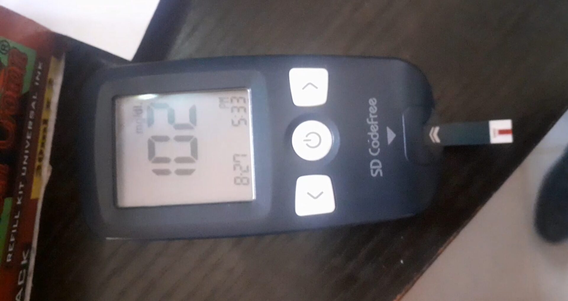
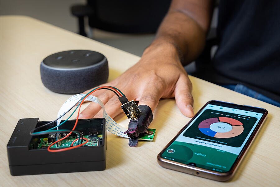
Unlike this device that makes use of Specimen A’s blood to measure the glucose level, our non-invasive glucose monitoring sensor works on the principle of optical methods. Using Near-Infrared (NIR) Spectroscopy where the NIR light interacts with glucose molecules, producing characteristic absorption patterns. By analyzing these patterns, glucose levels can be estimated. We used an infrared LED and a LDR sensor to detect these levels.
For NIR spectroscopy, you’ll want an infrared light source that emits in the near-infrared range (typically 800 nm to 940 nm). Specifically, you can use near-infrared light-emitting diodes (IR LEDs) in the 800 nm to 940 nm wavelength range. These LEDs are engineered to emit light in the NIR spectrum and are commonly used for various applications, including spectroscopy.
Also, AS7265x Triad: If you’re looking for a cost-effective solution, consider the AS7265x triad, which combines visible light (VL), ultraviolet (UV), and NIR sensors in a single package. The AS72653 sensor covers the NIR range (approximately 600 nm to 870 nm) and can be interfaced with an Arduino.
How the Non-Invasive ECG Sensor Work
The ECG used the low in and the high in pins connected as shown in the circuit diagram. These are the digital input pins. The custom function ecgSensor() was used to take the reading and the analog values were mapped and converted to the proper readings of accepted ECG values. These values are then displayed on a graph just like in the electrocardiograph.
Read Also…
- How to Build DIY Gas Leak Detector with Arduino and Blynk IoT
- IoT Pump Control for Efficient Irrigation Systems
- IoT Pump Control Irrigation System Using ESP32 Arduino
Circuit Design and Connections
The circuit diagram for measuring glucose is shown below. We used some LEDs as described above.
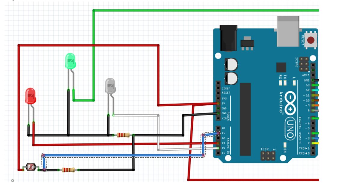
The setup diagram was drawn on fritzing IDE, the breadboard version. Here we used the types of LED for the design and a photocell to represent the emitters of different spectrum of light needed and the sensor that would detect the reflected light through the human skin respectively. According to Beer-Lambert’s law.
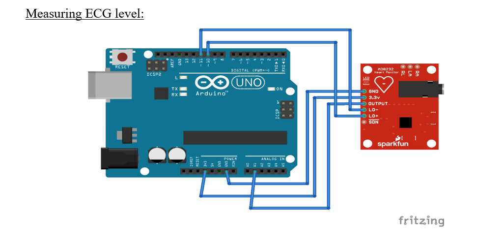
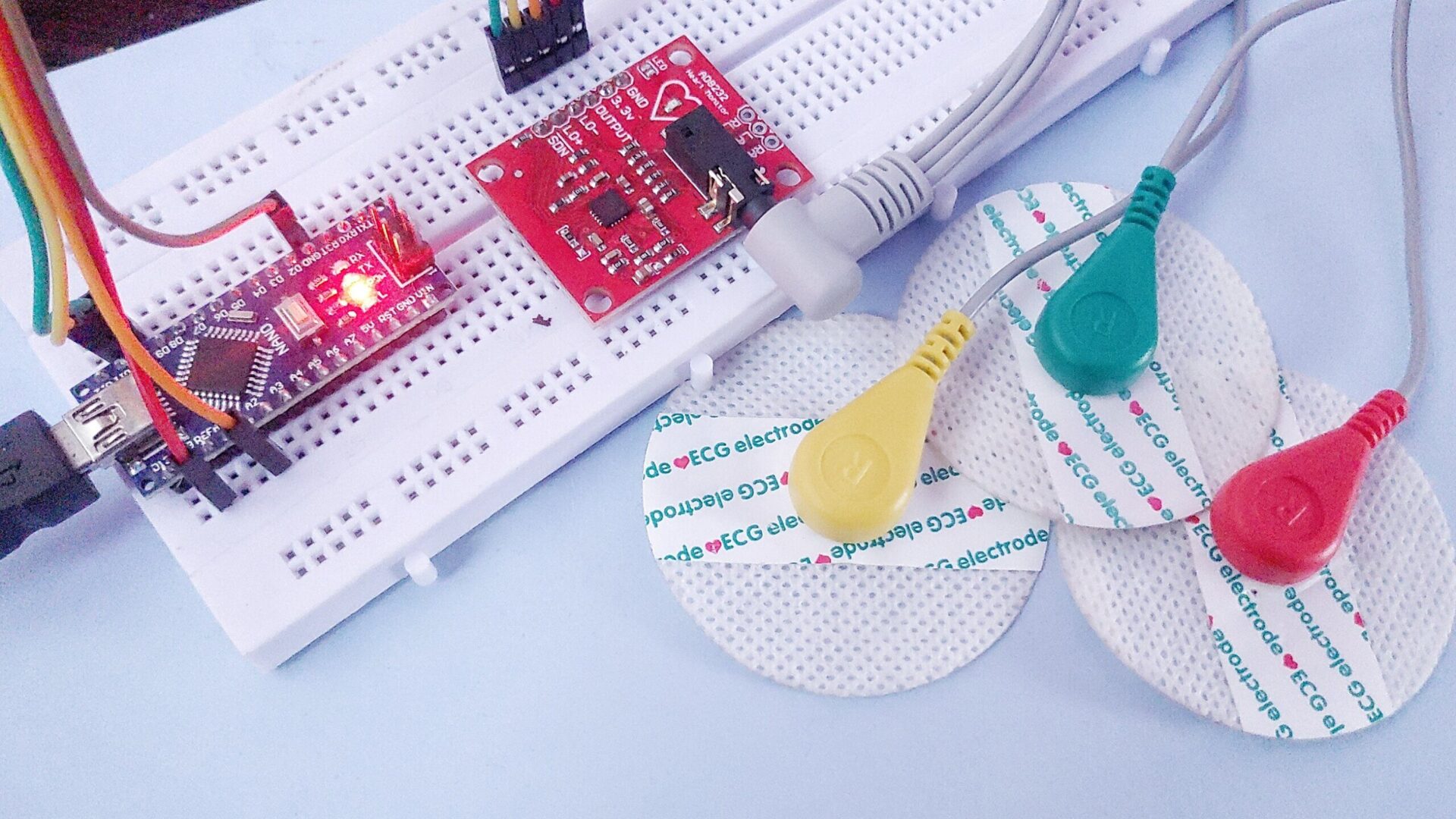
Here we connected the GND (ground) of the AD8232 sensor to the GND of the Arduino.
- Connected the 3.3V pin of the AD8232 to the 3.3V pin of the Arduino. Connected the OUTPUT pin of the AD8232 to the A0 analog input pin of the Arduino.
- Connect the LO- (lead-off negative) pin of the AD8232 to PIN 11 of the Arduino.
- Connect the LO+ (lead-off positive) pin of the AD8232 to PIN 10 of the Arduino.
- Leave the SDN (shutdown) pin unconnected.
Once connected, we can read the ECG signal from the AD8232 using the Arduino. We can also display the signal on a serial plotter or use Processing IDE for visualization.
Programming the Arduino
#include <EEPROM.h>
#include <SoftwareSerial.h>
#include <DallasTemperature.h>
#include <OneWire.h>
#include <LiquidCrystal.h>

SoftwareSerial mySerial(2, 3); // RX, TX
int sensor[] = {};

//4 pin of uno
#define ONE_WIRE_BUS 4

OneWire oneWire(ONE_WIRE_BUS);

DallasTemperature sensors(&oneWire);            // Pass the oneWire reference to Dallas Temperature.

LiquidCrystal lcd(12, 11, 10, 9, 8, 7);

#define greenLED  13
#define redLED  A4
#define blueLED A5

long randNumber;

float temp, bp, chloe1, chloe2, totalChlr;
int ecg1, ecg, pulseRate, glocoseSensor; //chekRandNumber;
 int changeTemp;


void generate(){
  randNumber = random(5, 10);
  Serial.println(randNumber);
 EEPROM.write(0, randNumber);
}

void setup(void){
  Serial.begin(115200);
  while (!Serial) { ; }
  // set the data rate for the SoftwareSerial port
  mySerial.begin(115200);
  //mySerial.println("Hello, world?");
  sensors.begin();
  lcd.begin(20,4);
  //define the pins for ECG sensor
  pinMode(6, INPUT); // Setup for leads off detection LO +
  pinMode(5, INPUT); // Setup for leads off detection LO -

  //the LEDs
  pinMode(greenLED, OUTPUT);
  pinMode(redLED, OUTPUT);
  pinMode(blueLED, OUTPUT);

  //print a welcome message
  lcd.setCursor(0, 0);
  lcd.print("      WELCOME   ");
  lcd.setCursor(0, 1);
  lcd.print("  Mr. Ameh Solomon");
  for(int x=0; x<19; x++){
   lcd.setCursor(x,2);
  lcd.print("*");
  delay(200);
  }
  for(int x=0; x<19; x++){
   lcd.setCursor(x,3);
  lcd.print("*");
  delay(200);
  }
  lcd.clear();
  lcd.setCursor(0, 0);
  lcd.print(" IoT Based Vascular");
  lcd.setCursor(0,1);
  lcd.print("   Blood Disease");
  lcd.setCursor(0,2);
  lcd.print("   Prevention And");
  lcd.setCursor(0, 3);
  lcd.print(" Detection Project");
  delay(4000);
  lcd.setCursor(0,0);
  lcd.print("Prepping Sensors");
  for(int x=16; x<19; x++){
   lcd.setCursor(x,0);
  lcd.print("*");
  delay(200);
  }
  for(int x=0; x<19; x++){
   lcd.setCursor(x,1);
  lcd.print("*");
  delay(200);
  }
  for(int x=0; x<19; x++){
   lcd.setCursor(x,2);
  lcd.print("*");
  delay(200);
  }
  for(int x=0; x<19; x++){
   lcd.setCursor(x,3);
  lcd.print("*");
  delay(200);
  }
  lcd.clear();

  randomSeed(analogRead(A3));

  generate();
}


float bodyTemp(){
  // Send the command to get temperatures
  sensors.requestTemperatures();
  Serial.println("Temperature is: ");
  // Why "byIndex"? You can have more than one IC on the same bus. 0 refers to the first IC on the wire
  temp = sensors.getTempCByIndex(0);


  return temp;

}


int ecgSensor(){
   ecg1 = analogRead(A0);
  if((digitalRead(5) == 1)||(digitalRead(6) == 1)){
Serial.println('!');
}
else{
  return ecg1;
}
//Wait for a bit to keep serial data from saturating
delay(100);
}


int pulseRateSensor(){
       pulseRate = ecg/2;
  return pulseRate;
}


float bloodPressure(){
 bp =  100.0/3.0;
 return bp;
}


int glucometer(){
  glocoseSensor = analogRead(A1);
  return glocoseSensor;

}


float chloresterolLevel(){
   int readChr = analogRead(A2);
   chloe2 = float(readChr);
   chloe1 /= 2.0;
  return chloe1, chloe2;
}


void loop(void){
  int chekRandNumber = EEPROM.read(0);
  bodyTemp();

  ecgSensor();
//  pulseRateSensor();
// bloodPressure();
// glucometer();
// pulseRateSensor();
// chloresterolLevel();

int roomTemp = temp;

if((roomTemp == 30) || (roomTemp == 29) || (roomTemp == 31) || (roomTemp == 28) || (roomTemp == 27) || (roomTemp == 26) || (roomTemp == 33) || (roomTemp == 32)){

changeTemp = 0;
ecg = 0;
bp = 0;
glocoseSensor = 0;
chloe1, chloe2 = 0;
}

else{
 changeTemp = temp;
changeTemp += 2;
if((ecg1 == 1023) || (ecg1 <=40)){
  ecg = 0;
}

if((ecg1 > 40) && (ecg1 < 1023)) {
  if(chekRandNumber == 5){
    ecg = 81;
    pulseRate = 60;
    bp = 1.50;
    glocoseSensor = 102;
    chloe1 = 51.12;
    chloe2 = 46.75;
    totalChlr = chloe1 + chloe2 + 3.9;
  }

  if(chekRandNumber == 6){
    ecg = 90;
    pulseRate = 70;
    bp = 1.48;
    glocoseSensor = 124;
    chloe1 = 65.12;
    chloe2 = 50.75;
    totalChlr = chloe1 + chloe2 + 3.9;
  }

  if(chekRandNumber == 7){
    ecg = 95;
    pulseRate = 80;
    bp = 1.42;
    glocoseSensor = 112;
    chloe1 = 75.12;
    chloe2 = 70.75;
    totalChlr = chloe1 + chloe2 + 3.9;
  }

  if(chekRandNumber == 8){
    ecg = 100;
    pulseRate = 90;
    bp = 1.40;
    glocoseSensor = 110;
    chloe1 = 61.32;
    chloe2 = 51.45;
    totalChlr = chloe1 + chloe2 + 3.9;
  }

  if(chekRandNumber == 9){
    ecg = 110;
    pulseRate = 100;
   bp = 1.37;
    glocoseSensor = 102;
    chloe1 = 72.23;
    chloe2 = 52.15;
    totalChlr = chloe1 + chloe2 + 3.9;
  }

}

}


Serial.print("random Number ");
Serial.print(chekRandNumber);
Serial.print(" temp: ");
Serial.print(temp);
Serial.print(" Body temp: ");
Serial.print(changeTemp);
// send the value of analog input 0:
Serial.print(" ECG sensor ");
Serial.println(ecg);
Serial.print("pulse rate: ");
Serial.print(pulseRate);
Serial.print(" Blood Pressure: ");
Serial.print(bp);
Serial.print(" Glucose Level " );
Serial.println(glocoseSensor);
Serial.print("Cholestrol I ");
Serial.print(chloe1);
Serial.print(" Cholesterl II ");
Serial.print(chloe2);
Serial.print(" Total Cholesterl ");
Serial.println(totalChlr);


lcd.setCursor(0,0);
lcd.print("T: ");
lcd.print(changeTemp);
lcd.print("'C");
lcd.setCursor(10,0);
lcd.print("ECG: ");
 lcd.print(ecg);
 lcd.print("ms  ");

 lcd.setCursor(0,1);
 lcd.print("Glu:   ");
 lcd.print(glocoseSensor);
 lcd.print("mg/dL");

 lcd.setCursor(0,2);
 lcd.print("BP:    ");
 lcd.print(bp);
 lcd.print("mmHg");

 lcd.setCursor(0,3);
 lcd.print("Totl Chlo: ");
 lcd.print(totalChlr);
 lcd.print("mg/dL");


  sensor[0] = changeTemp;
  sensor[1] = ecg;
  sensor[2] = pulseRate;
  sensor[3] = bp;
  sensor[4] = glocoseSensor;
  sensor[5] = chloe1;
  sensor[6] = chloe2;
  sensor[7] = totalChlr;


    mySerial.println("tp = " + String(sensor[0]));
    delay(100);
    mySerial.println("ec = " + String(sensor[1]));
    delay(100);
    mySerial.println("pr = " + String(sensor[2]));
    delay(100);
    mySerial.println("bp = " + String(sensor[3]));
    delay(100);
    mySerial.println("gl = " + String(sensor[4]));
    delay(100);
    mySerial.println("ch1 = " + String(sensor[5]));
    delay(100);
    mySerial.println("ch2 = " + String(sensor[6]));
    delay(100);
    mySerial.println("tch = " + String(sensor[7]));
    delay(100);
}
Explanation of Arduino Source Code
The above source code is self explanatory, we included comment lines to what each line of code does. The source code above is a much larger code of a cardiovascular disease and prevention project.
Data Processing and Display
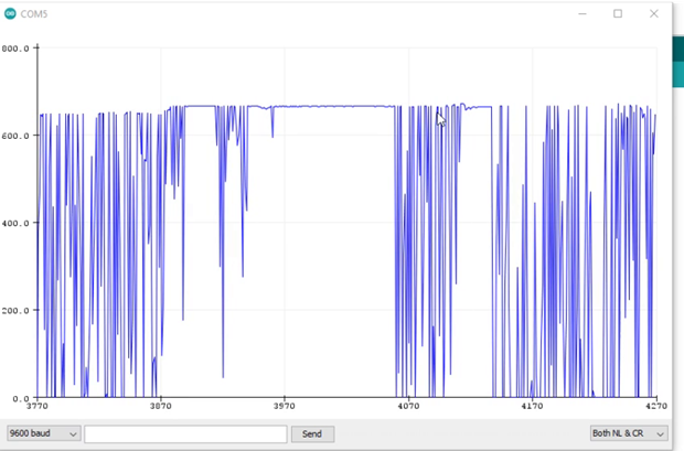
This is the graph of the ECG sensors taking the readings the of the pulse rate of the specimen A. We can see that the readings of each pulse that is being detected and measured.
The graphical representation is converted to numerical representation and we were able to display these readings on an LCD module. Although this is part of the whole code.
Calibration and Testing
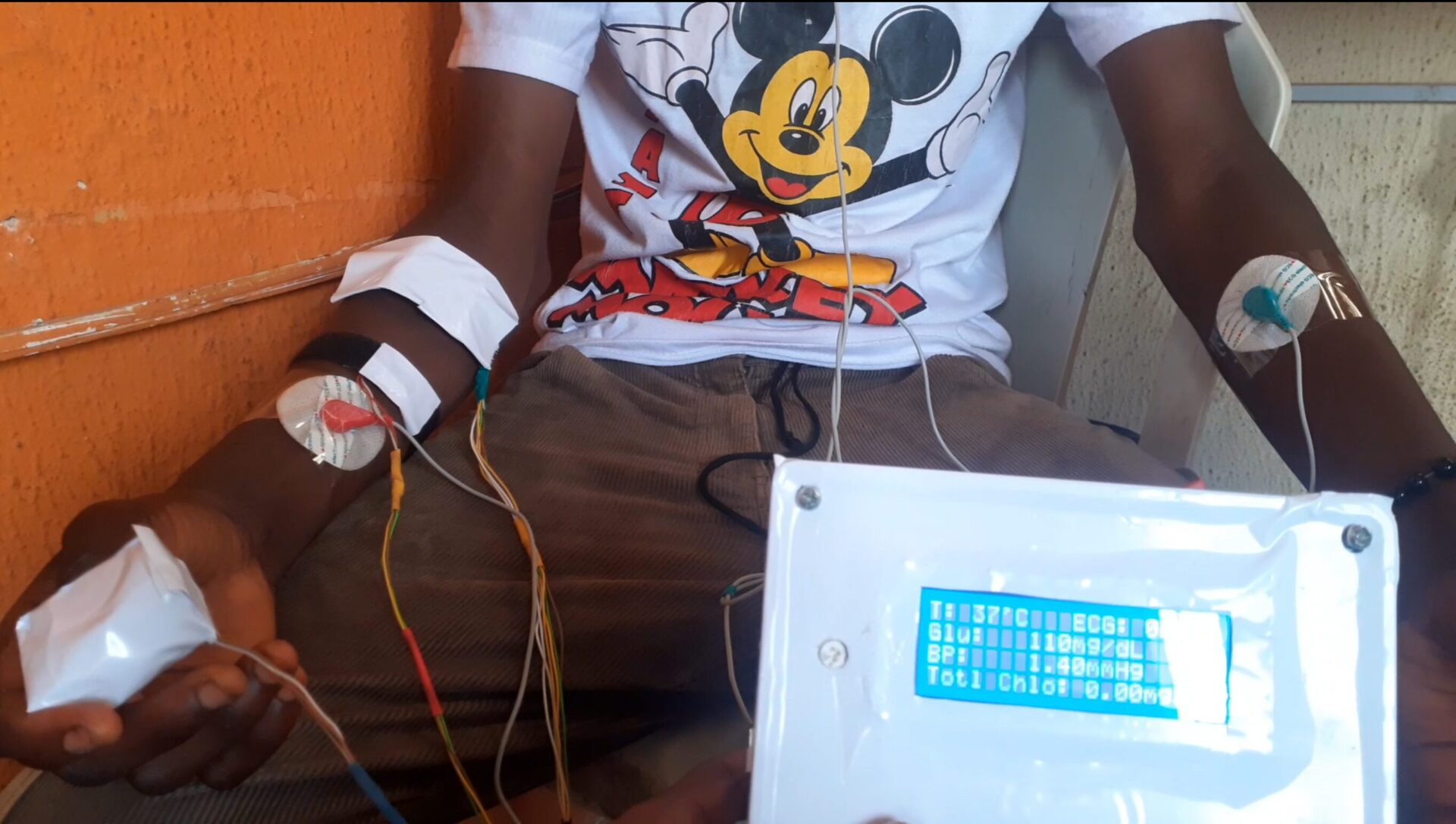
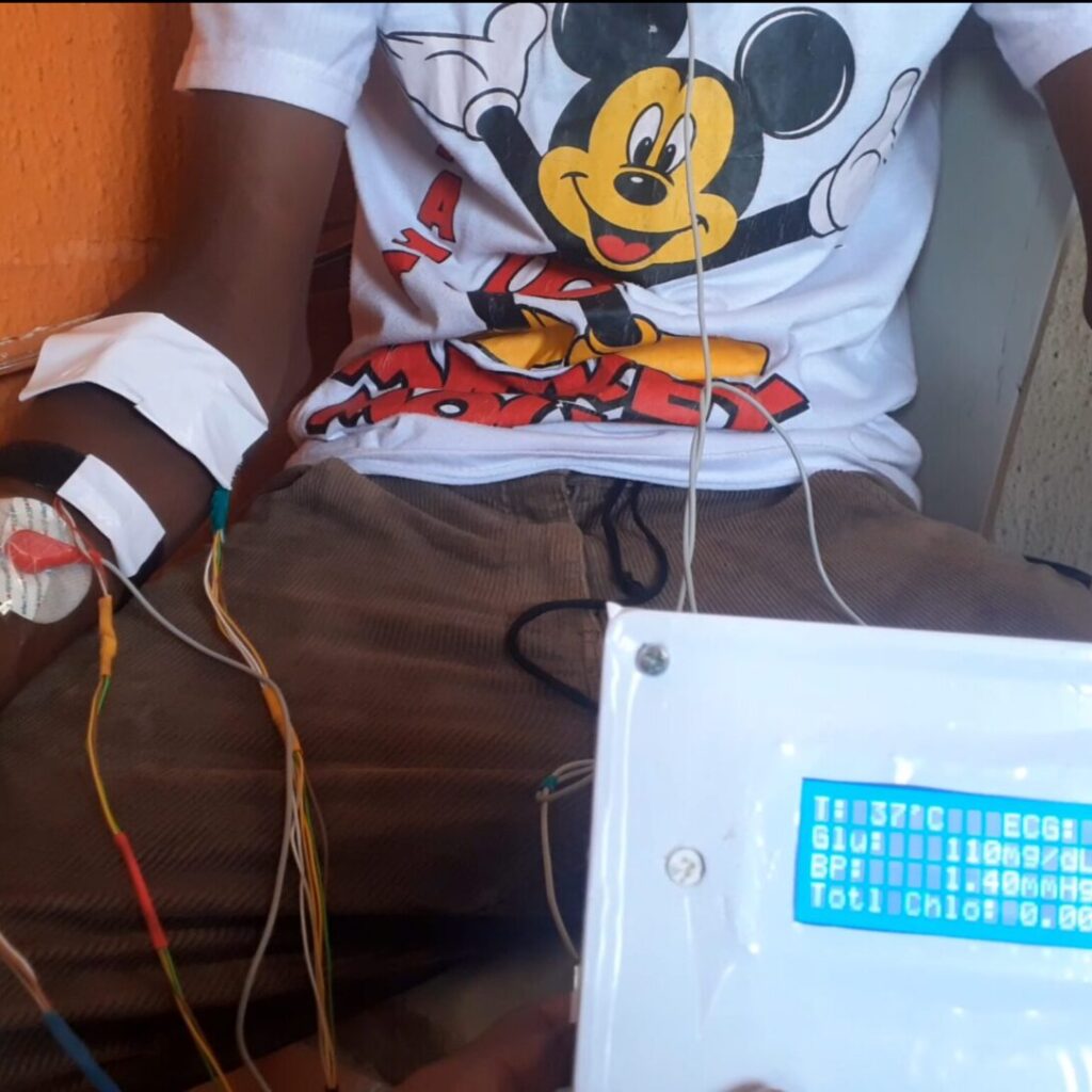
The calibration of the sensors were done during the testing phase of the project. The Non-Invasive Glucose and ECG levels Monitoring using Arduino worked as programmed. And we can see the readings of Glucose and the ECG sensors on the LCD screen.
Limitations and Challenges
Despite the advancements, non-invasive glucose and ECG monitoring still face limitations and challenges. These include:
- Accuracy and reliability: Ongoing refinement is needed to ensure the accuracy and reliability of non-invasive monitoring systems.
- Regulatory approvals: Securing regulatory approvals and certifications is crucial for widespread adoption.
- Cost and accessibility: Making non-invasive monitoring systems affordable and accessible to all is essential.
By addressing these challenges, we can unlock the full potential of non-invasive glucose level and ECG level monitoring, transforming the lives of millions worldwide.
FAQs on Glucose and ECG Levels Monitoring
1. How accurate are non-invasive glucose sensors?
Non-invasive glucose sensors have varying levels of accuracy, depending on the technology used. Some optical sensors have shown accuracy comparable to invasive methods, while others may have lower accuracy. It’s essential to research and chooses a sensor with high accuracy and reliability.
2. Can I use any Arduino board for this project?
Not all Arduino boards are suitable for glucose and ECG monitoring projects. You’ll need a board with analog input capabilities, such as Arduino Uno, Arduino Nano, or Arduino Due. Additionally, consider the board’s processing power, memory, and compatibility with sensors.
3. What are the best sensors for beginners?
For beginners, consider starting with:
- Glucose sensors: Optical sensors like the GlucoTrack or the Dexcom G5
- ECG sensors: Simple electrodes like the AD8232 or the ECG Click
These sensors are relatively easy to use, have good documentation, and are widely available.
4. How can I improve the accuracy of my readings?
To improve accuracy:
- Calibrate your sensors regularly
- Use proper sensor placement and positioning
- Ensure good contact between sensors and skin
- Use noise reduction techniques (e.g., filtering, averaging)
- Consider using multiple sensors for redundancy
5. What are the safety considerations when working with ECG sensors?
When working with ECG sensors:
- Ensure proper electrode placement to avoid electrical shock
- Use electrodes with built-in safety features (e.g., lead-off detection)
- Avoid using ECG sensors near water or in humid environments
- Be aware of potential interference from other electrical devices
- Consult medical professionals if you’re unsure about any aspect of ECG monitoring

