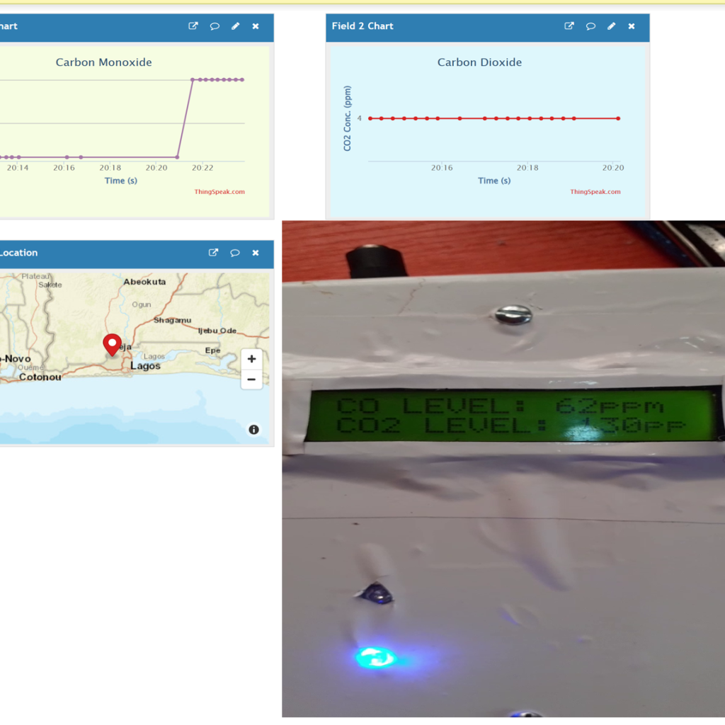
In the design and construction of the Carbon Monoxide (CO) and Carbon Dioxide (CO2) monitoring system, certain components and materials were used. The various components needed was assembled to do the specific function of the device being able to detect CO and CO2 gases that are emitted around the vicinity where people live, then alert the residents of such emissions using audio alerts. The measured parameters are also exported to a Thingspeak IoT dashboard, where it can be further analyzed by an expert on the air quality index of such an area.
Material/Components Needed For Carbon Monoxide and Carbon Dioxide Monitoring
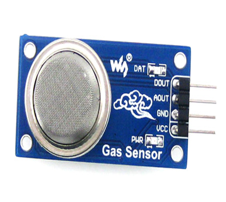
The MQ2 gas sensor module was used to measure the level of CO in the vicinity the project. The MQ-2 sensor is a gas sensor used to measure the amount of CO, CO2 and other dangerous combustible gases concentrations like LPG etc. It can operate at temperature between -20°C and 50°C range. This sensor can consume voltages less 150mA current at 5V rating and has accuracy of detecting gas concentrations between 100 to 10,000ppm.
• MQ-135 Air Quality Gas Sensor Module
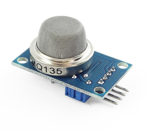
This gas sensor is very sensitive to tin oxide compound (SnO2), which has lower conductivity in clean air. The gas sensor works thus; when the target combustible gas exist within its range of sensory field, it would change its electrical conductivity and we can use this with a microcontroller to map out range of threshold values. We can convert change of conductivity to correspond output signal of gas concentration. This MQ135 gas sensor module has high sensitivity to Ammonia, Sulfide and Benzene steam. We also used it sensitive nature to detect NO3.
| ITEM DESCRIPTION | QUANTITY |
| MQ-2 AIR QUALITY SENSOR | 1 |
| POWER SUPPLY | 1 |
| LEDs | 6 |
| RESISTORS | 6 |
| ARDUINO PROMINI | 1 |
| CONNECTING WIRES | 2 YARDS |
| CASING | 1 |
| VERO BOARD | 1 |
| BREADBOARD MODELLING | 1 |
| SOLDER | 1 |
| SOLDERING IRON | 1 |
| PIEZO BUZZER | 1 |
| OLED SCREEN | 1 |
| MISCELLANEOUS |
Schematic Diagram of Carbon Monoxide and Carbon Dioxide Monitoring Project
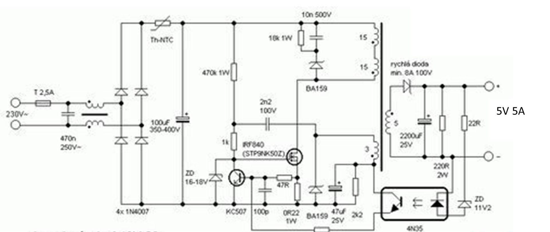
The schematic diagram of the power supply is shown above. It is a basic Switch Mode Power Supply (SMPS). It uses (220-240)V AC input and gives 5V 5A output. The components are to be connected as shown above. Alternatively, one can opt for the use of an already made power supply that can supply 5V, up to 2A of current rating.
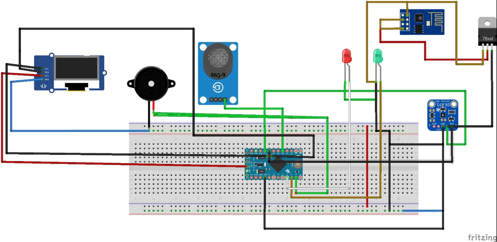
The microcontroller circuit diagram is shown above. It is built around the Arduino Pro-Mini board. The MQ2 gas sensor module was connected to the analog pin of the Arduino Pro-Mini board; the analog pin 1 to be exact. While the MQ135 was connected to analog pin 2. The power rails for these gas sensor modules were connected to the 5V and ground pins accordingly.
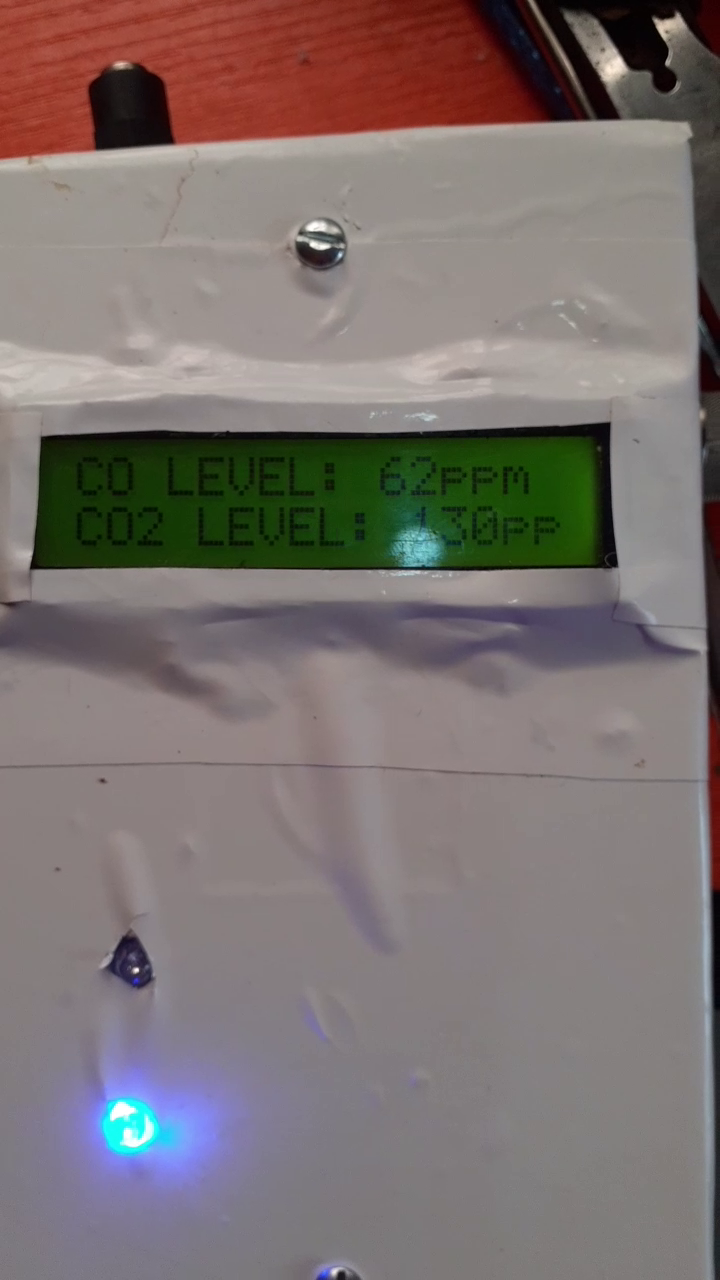
We used two LEDs as external indicators for the users around where the device is to be installed. A buzzer is also added to alert people to harmful gas levels. We used the OLED module to display what the measured readings. Whereas, the ESP-01 is used to send the measured readings to the Thingspeak IoT dashboard.
Setting Up The Thingspeak IoT Dashboard
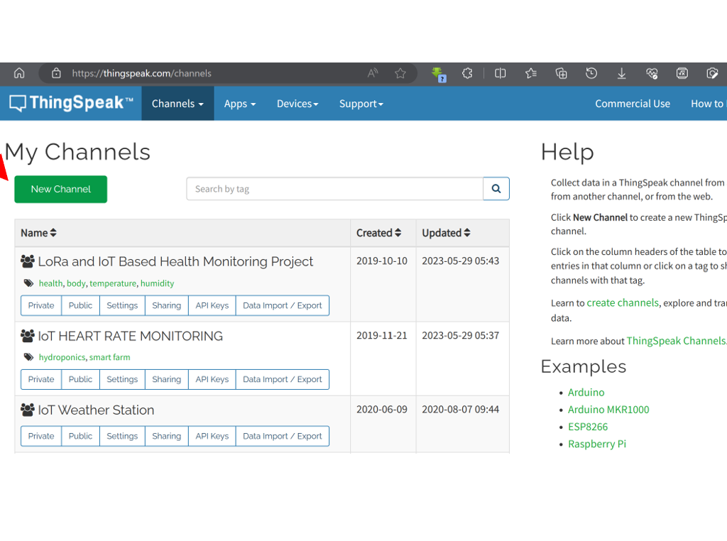
Head over to Thingspeak dashboard, after signing up, click on New Channel to create a channel. You can type the name of your new channel, and select how many widget/fields you want to the channel to have. You are allowed a maximum of 8 fields that can display your data sent.
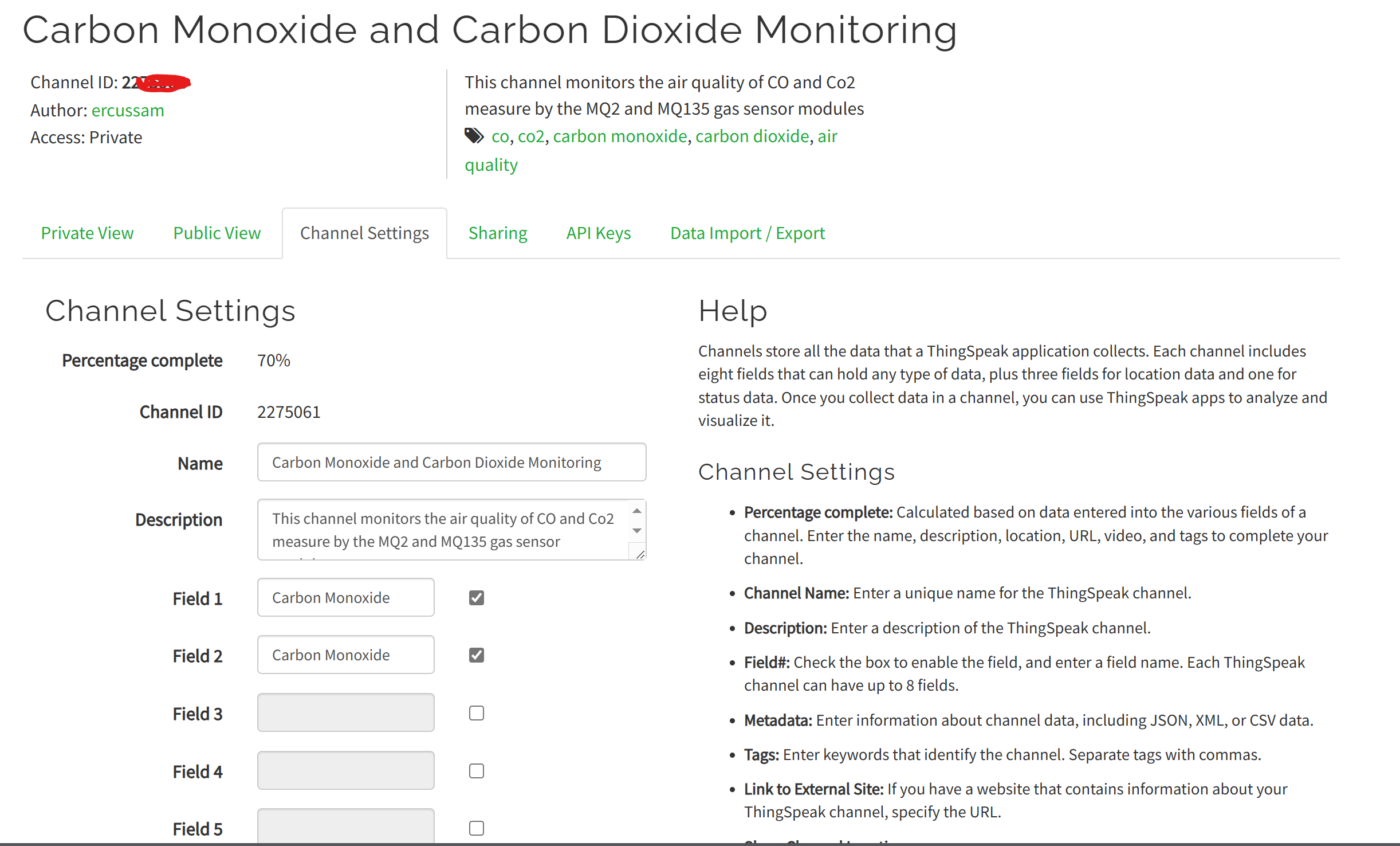
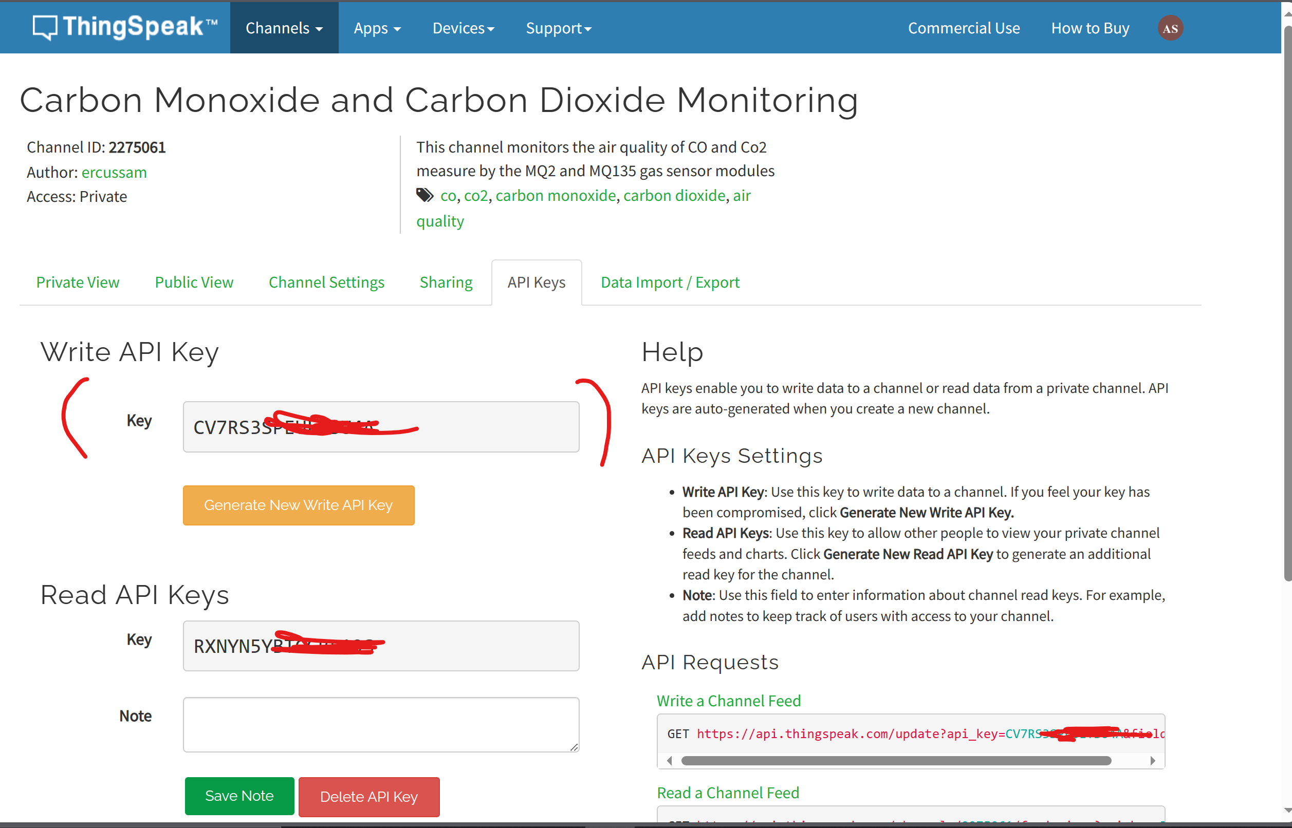
Once you are done setting up your channel, remember to copy off your channel ID and your Thingspeak write code. These are important for the source code below. You can find the Write Code by navigating to API Keys and copying the key in the Write API Box.
Once you are done, save the changes made to your channel and navigate back to the home page of the channel and you can choose to customize the look of each field widget or simply leave it as it is.
Read More Posts Like This
- IoT Based Solar Panel Monitoring using Arduino Voltage Sensor Module
- How To Build IoT Tamper-Proof Energy Meter Using Arduino & WiFi
- IoT Irrigation System With NPK Sensor With Arduino & Cayenne
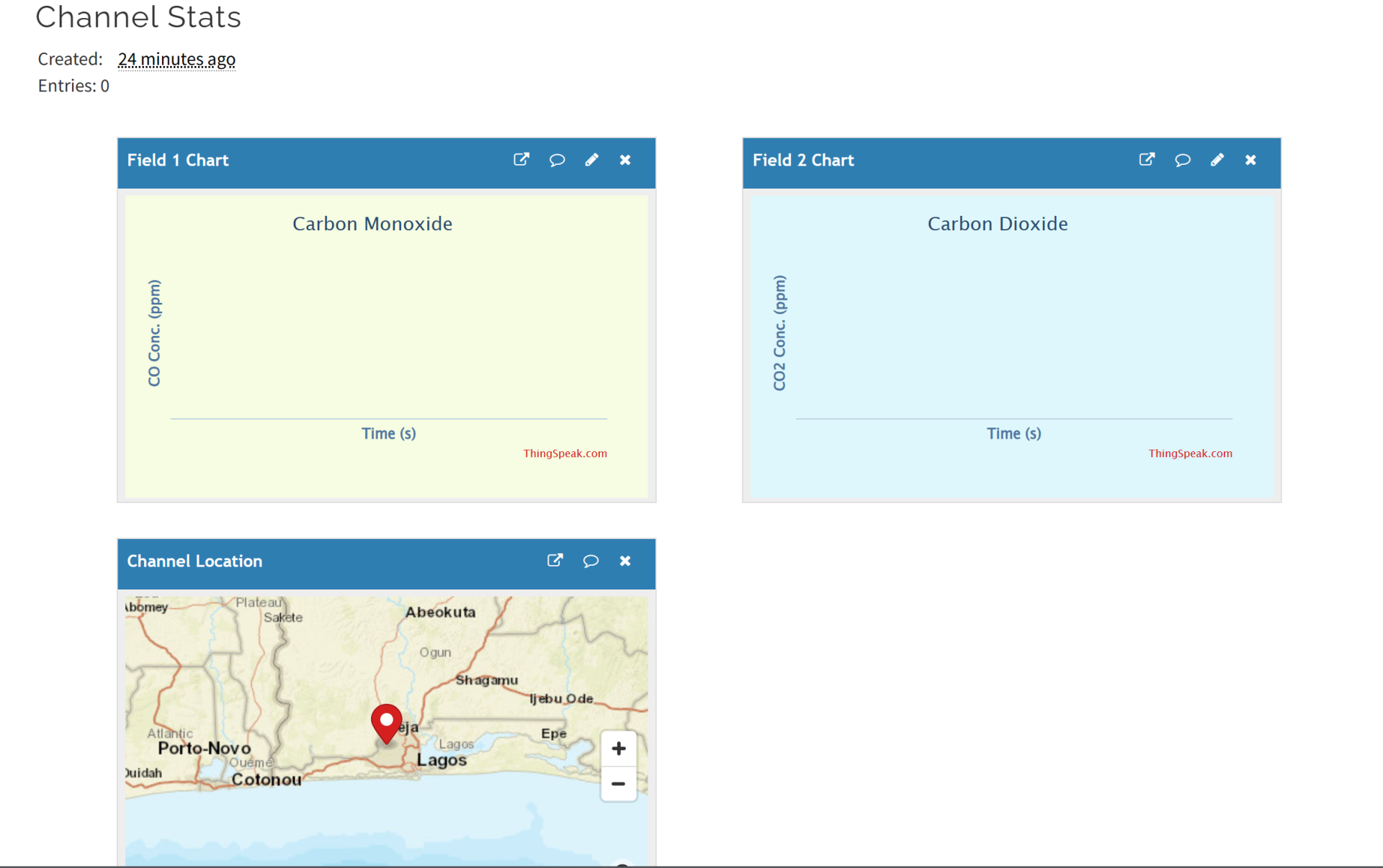
We customized ours by changing the background of each field using hexadecimal color codes. This gave us better aesthetic view than the Thingspeak default view.
Carbon Monoxide and Carbon Dioxide Monitoring: The Arduino Sketch
Click here to download the LCD with Thingspeak version of this below code.
#include "U8glib.h"
U8GLIB_SH1106_128X64 u8g(U8G_I2C_OPT_NONE);
// Thingspeak
String statusChWriteKey = "JM4U311Z22G153F8";  // Status Channel id: 385184
#include <SoftwareSerial.h>
SoftwareSerial EspSerial(4, 5); // Rx,  Tx
#define HARDWARE_RESET 6
// constants won't change. Used here to set a pin number:
const int redLED =  7;// the number of the LED pin
const int blueLED =  8;// the number of the LED pin
 int buzzer = 9;
 bool iotBuzzer = 0;
 bool iotRedLED = 0;
 bool iotBlueLED = 0;

// Variables will change:
int ledState = LOW;             // ledState used to set the LED
int buzzerState = LOW;
// Generally, you should use "unsigned long" for variables that hold time
// The value will quickly become too large for an int to store
unsigned long previousMillis = 0;        // will store last time LED was updated

// constants won't change:
const long interval = 500;           // interval at which to blink (milliseconds)

int ledState1 = LOW;
unsigned long previousMillis1 = 0;
int sensorValue, sensorValue2;
// Variables to be used with timers
long writeTimingSeconds = 17; // ==> Define Sample time in seconds to send data
long startWriteTiming = 0;
long elapsedWriteTime = 0;
int spare = 0;
boolean error;

void draw(void) {
  u8g.setFont(u8g_font_profont12);
  u8g.setPrintPos(0, 10);
  u8g.print(" WELCOME Mr. KINGMATE\"");
  u8g.setPrintPos(8, 25);
  u8g.print("CARBON MONOXIDE AND ");
  u8g.setPrintPos(8, 40);
  u8g.print("CARBON (IV) OXIDE");
  u8g.setPrintPos(8, 55);
  u8g.print("DETECTION PROJECT");
}
void setup(){
  Serial.begin(9600);
  pinMode(HARDWARE_RESET,OUTPUT);
  pinMode(buzzer,OUTPUT);
  pinMode(buzzer,OUTPUT);
  pinMode(blueLED, OUTPUT);
  pinMode(redLED, OUTPUT);
  digitalWrite(HARDWARE_RESET, HIGH);
   EspSerial.begin(9600);
  EspHardwareReset();
  startWriteTiming = millis(); // starting the "program clock"

u8g.firstPage();
      do {
        draw();
         delay(2000);
            }
while(u8g.nextPage() );
}

void redled(){
  unsigned long currentMillis1 = millis();

  if (currentMillis1 - previousMillis1 >= interval) {
    // save the last time you blinked the LED
    previousMillis1 = currentMillis1;

    // if the LED is off turn it on and vice-versa:
    if (ledState1 == LOW) {
      ledState1 = HIGH;
    } else {
      ledState1 = LOW;
    }

    // set the LED with the ledState of the variable:
    digitalWrite(redLED, ledState1);
  }
}


void blueled(){
  unsigned long currentMillis = millis();

  if (currentMillis - previousMillis >= interval) {
    // save the last time you blinked the LED
    previousMillis = currentMillis;

    // if the LED is off turn it on and vice-versa:
    if (ledState == LOW) {
      ledState = HIGH;
    } else {
      ledState = LOW;
    }

    // set the LED with the ledState of the variable:
    digitalWrite(blueLED, ledState);
  }
}
void buzzerOn(){
  unsigned long currentMillis = millis();

  if (currentMillis - previousMillis >= interval) {
    // save the last time you blinked the LED
    previousMillis = currentMillis;
    // if the LED is off turn it on and vice-versa:
    if (buzzerState == LOW) {
      buzzerState = HIGH;
    } else {
      buzzerState = LOW;
    }
    // set the LED with the ledState of the variable:
    digitalWrite(buzzer, buzzerState);
  }
}
void loop(){
  start: //label
  error=0;

  elapsedWriteTime = millis()-startWriteTiming;

  if (elapsedWriteTime > (writeTimingSeconds*1000)) {

u8g.firstPage();
  do {
   readSensors();
  } while( u8g.nextPage() );


    writeThingSpeak();
    startWriteTiming = millis();
  }

  if (error==1) //Resend if transmission is not completed
  {
    Serial.println(" <<<< ERROR >>>>");
    delay (2000);
    goto start; //go to label "start"
  }
}

/********* Read Sensors value *************/
void readSensors(void){
  sensorValue = analogRead(A0);
   sensorValue2 = analogRead(A1);
 if ((sensorValue2 >= 170) || (sensorValue >=170)){
  iotBuzzer = 1;
 iotRedLED = 1;
 iotBlueLED = 0;
 digitalWrite(buzzer, HIGH);
      redled();
     // Serial.println("Environment too harrmful");
   //.setPrintPos(0, 10);
   u8g.drawStr( 0, 10, "Hello World!");
   u8g.setPrintPos(8, 25);
  u8g.print("CO LEVEL: ");
  u8g.print(sensorValue);
  u8g.print(" ");
 u8g.print("ppm");
  u8g.setPrintPos(8, 40);
  u8g.print("CO2 LEVEL: ");
  u8g.print(sensorValue2);
  u8g.print(" ");
 u8g.print("ppm");
 u8g.setPrintPos(8, 55);
  u8g.print(" PLS STAY AWAY");
  }

if ((sensorValue2 <= 160) || (sensorValue <= 160) ){
    iotBuzzer = 0;
 iotRedLED = 0;
  iotBlueLED = 1;
  digitalWrite(buzzer,LOW);
   blueled();
     // Serial.println("ALL GOOD! ");
     u8g.setPrintPos(0, 10);
  u8g.print(" GREEN ALERT NOTICE");
   u8g.setPrintPos(8, 25);
  u8g.print("CO LEVEL: ");
  u8g.print(sensorValue);
  u8g.print(" ");
 u8g.print("ppm");
  u8g.setPrintPos(8, 40);
  u8g.print("CO2 LEVEL: ");
  u8g.print(sensorValue2);
  u8g.print(" ");
 u8g.print("ppm");
  }
 Serial.print("sensorValue - ");
  Serial.println(sensorValue);
    Serial.print("sensorValue2 - ");
     Serial.println(sensorValue2);
      Serial.print(" ");
    Serial.print(iotBuzzer);
    Serial.print(" ");
    Serial.print(iotRedLED);
     Serial.print(" ");
    Serial.println(iotBlueLED);
    //delay(wait);
}

/********* Conexao com TCP com Thingspeak *******/
void writeThingSpeak(void){
  startThingSpeakCmd();
  // preparacao da string GET
  String getStr = "GET /update?api_key=";
  getStr += statusChWriteKey;
  getStr +="&field1=";
  getStr += String(sensorValue);
  getStr +="&field2=";
  getStr += String(sensorValue2);
  getStr +="&field3=";
  getStr += String(iotBuzzer);
  getStr +="&field4=";
  getStr += String(iotRedLED);
  getStr +="&field5=";
  getStr += String(iotBlueLED);
  getStr += "\r\n\r\n";
  sendThingSpeakGetCmd(getStr);
}

/********* Reset ESP *************/
void EspHardwareReset(void){
  Serial.println("Reseting.......");
  digitalWrite(HARDWARE_RESET, LOW);
  delay(500);
  digitalWrite(HARDWARE_RESET, HIGH);
  delay(8000);//Tempo necessário para começar a ler
  Serial.println("RESET");
}
/********* Start communication with ThingSpeak*************/
void startThingSpeakCmd(void){
  EspSerial.flush();//limpa o buffer antes de começar a gravar
  String cmd = "AT+CIPSTART=\"TCP\",\"";
  cmd += "184.106.153.149"; // Endereco IP de api.thingspeak.com
  cmd += "\",80";
  EspSerial.println(cmd);
  Serial.print("enviado ==> Start cmd: ");
  Serial.println(cmd);
  if(EspSerial.find("Error"))
  {
    Serial.println("AT+CIPSTART error");
    return;
  }
}
/********* send a GET cmd to ThingSpeak *************/
String sendThingSpeakGetCmd(String getStr)
{
  String cmd = "AT+CIPSEND=";
  cmd += String(getStr.length());
  EspSerial.println(cmd);
  Serial.print("enviado ==> lenght cmd: ");
  Serial.println(cmd);
  if(EspSerial.find((char *)">"))
  {
    EspSerial.print(getStr);
    Serial.print("enviado ==> getStr: ");
    Serial.println(getStr);
    delay(500);//tempo para processar o GET, sem este delay apresenta busy no próximo comando

    String messageBody = "";
    while (EspSerial.available())
    {
      String line = EspSerial.readStringUntil('\n');
      if (line.length() == 1)
      { //actual content starts after empty line (that has length 1)
        messageBody = EspSerial.readStringUntil('\n');
      }
    }
    Serial.print("MessageBody received: ");
    Serial.println(messageBody);
    return messageBody;
  }
  else
  {
    EspSerial.println("AT+CIPCLOSE");     // alert user
    Serial.println("ESP8266 CIPSEND ERROR: RESENDING"); //Resend...
    spare = spare + 1;
    error=1;
    return "error";
  }
}
Explanation of The Arduino Source Code
The source code uses the U8glib library to display texts and reading on the OLED screen. It uses the HTTPs protocol to send data to the Thingspeak dashboard through the ESP-01 module. We created a different function to display the measured reading and a different function to send the data to Thingspeak.
Also, we printed on the thingspeak dashboard if the warning sings are turned on when the harmful gaseous levels are detected by the device. Each Thingspeak channel has a write key, this is important and it is typed in the source code above.
Results
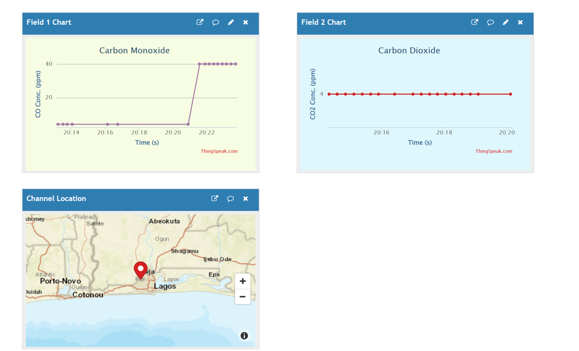
The project design was tested in the presence of very limited oxygen supply. Smoky vicinity caused by candles that were put off suddenly. And, also burning paper smokes, this was brought close to the sensors nd it was noted to sent the read LED indicator on. The was a lag in the display as the Thingspeak IoT dashboard was to be updating these changes and this interfered with the display. And it was noticed that the CO sensor was very sensitive to this gas concentration and quickly started buzzing alarm to signify unsafe environment with the IoT update.
Conclusion
The Carbon Monoxide and Carbon Dioxide Monitoring Project has been designed and it is found to be working as programmed. We can detect CO and CO2 within the vicinity is being installed. The device could monitor and notify us when the CO and CO2 around us is at alarming rates. Let us know what you think of this project in the comment below.

