In today’s post, we will be building an Internet of Things (IoT) solar panel remote monitoring system using an Arduino board, a voltage sensor, and the Blynk IoT dashboard. By the end of this tutorial, we will have successfully measured the voltage output of a PV (solar) panel and then sent that data in real time to a remote dashboard on the Blynk server, where it can be accessed from anywhere around the globe.
Go through this post to learn more about measuring the voltage of a solar panel.
Solar Panel Remote Monitoring System: Materials Needed
- Arduino Uno
- Voltage Sensor
- Solar panel 21.5V VoC, 20W
- ESP8266-01
- ESP8266 -12E
All these components can be bought on our online store. Alternatively, all the previous written tutorials on voltage measurements of PV are already detailed here. Read up more on this link. Let us proceed to how to hook this up to an Arduino Uno board, connect the ESP8266-01 WiFi module to it and send the data to cloud server of Blynk.
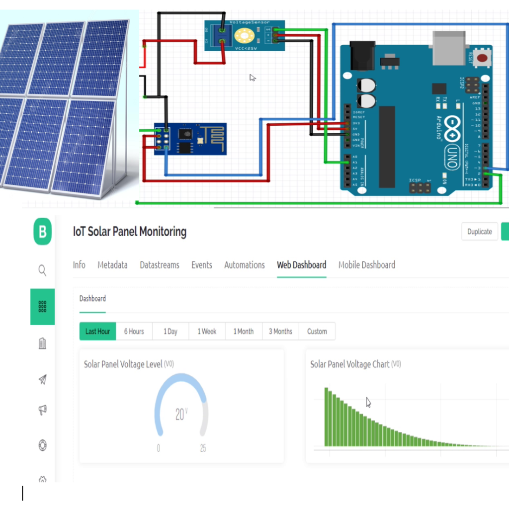
The Circuit Diagram of Solar Panel Remote Monitoring System
The ESP8266-01 (ESP-01) module is a small inexpensive WiFi module that is capable of host Access Point (A.P) and connecting to a server (STA mode). We connected this according to the diagram above. More details of the pin out diagram is shown below.

The ESP-01 uses 3.3V logic level. But it also required more current that the normal Arduino 3.3V port can provide. We however tried this and it worked but sometimes when there are other loads it may disturb it. It is usually wise to give it a stable 3.3V from an external power supply.
Explanation of circuit diagram
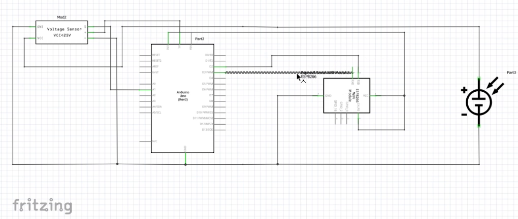
The circuit diagram for 3.3V, 5V, 9V, 12V and 24V uses the same source code (Arduino Sketch) given below. The battery level can be increased from 3.3V to 24V. and connected as shown above. Once this was done, connect the Arduino uno board to the Personal Computer (PC), power up the Arduino IDE and copy the sketch given below.
Setting Up the Blynk IoT Dashboard
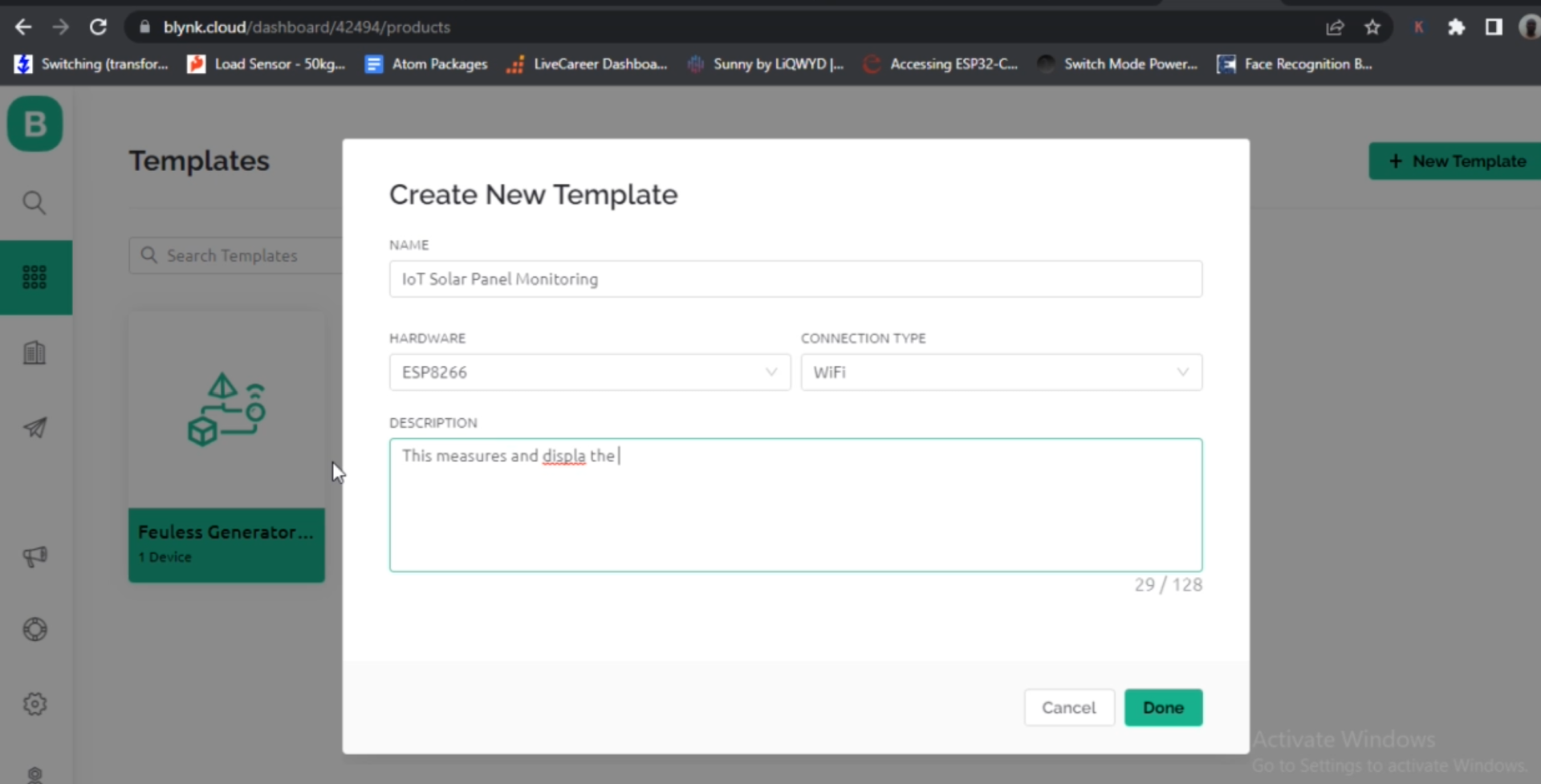
After signing up and signing into your Blynk account, create a new device and pick a name for your project. In our example here, we picked the name IoT Solar Panel Monitoring. Once we are done with the device name creation, we proceed to to adding the widget to holding the IoT remote monitoring.
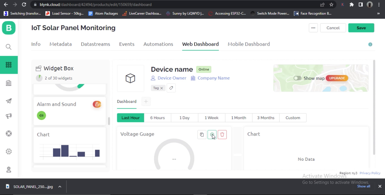
We used the gauge and chart widgets for this. The guage name was changed to Voltage Guage, this helped us to quickly identify it was displaying the voltage measured by the voltage sensor module. Ensure when configuring the widgets you select the proper virtual pin and data type you are expecting to be displayed by the widget. See the YouTube video for more explanation. When the web dashboard is all done and ready. You can add your device to your template.
Remember to copy your template ID, template name and Authentication token from the template dashboard because this will be need in the Arduino sketch that will be coded below.
Solar Panel Remote Monitoring System: The Source Code (Arduino Sketch)
// Template ID, Device Name and Auth Token are provided by the Blynk.Cloud
// See the Device Info tab, or Template settings
#define BLYNK_TEMPLATE_ID "XXXXXXXXXXXXXXXX"
#define BLYNK_TEMPLATE_NAME "XXXXXXXXXXXXXXXXX"
#define BLYNK_AUTH_TOKEN "XXXXXXXXXXXXXXXXXXX"

// Comment this out to disable prints and save space
#define BLYNK_PRINT Serial

float PVr1 = 30000.0;
float PVr2 = 7500.0;
float batteryVoltSensor, vinBattery;
const int voltagePinBattery = A1;

#include <ESP8266_Lib.h>
#include <BlynkSimpleShieldEsp8266.h>

char auth[] = BLYNK_AUTH_TOKEN;

// Your WiFi credentials.
// Set password to "" for open networks.
char ssid[] = "Galaxy A51 917E";
char pass[] = "ancsucre21";

// Hardware Serial on Mega, Leonardo, Micro...
//#define EspSerial Serial1

// or Software Serial on Uno, Nano...
#include <SoftwareSerial.h>
SoftwareSerial EspSerial(2, 3); // RX, TX

// Your ESP8266 baud rate:
#define ESP8266_BAUD 115200  //9600 //115200

ESP8266 wifi(&EspSerial);

BlynkTimer timer;

// This function sends Arduino's up time every second to Virtual Pin (5).
// In the app, Widget's reading frequency should be set to PUSH. This means
// that you define how often to send data to Blynk App.
void myTimerEvent(){
 //now doing calculations
  batteryVoltSensor = analogRead(voltagePinBattery);
 batteryVoltSensor = (batteryVoltSensor * 5.0)/1023.0;
 vinBattery = batteryVoltSensor/(PVr2/(PVr1+PVr2));

 int sensor = analogRead(A2);
int sensor2 = analogRead(A1);
  Blynk.virtualWrite(V0, vinBattery);
  //Blynk.virtualWrite(V1, sensor);
  Blynk.virtualWrite(V1, sensor2);


Serial.print("DC Measured Voltage : ");
Serial.print(vinBattery);
Serial.print(" Sensor Reading : ");
Serial.print(sensor2);
Serial.print(" millis count:");
Serial.println(millis() / 1000);
 delay(1000);
}

void setup()
{
  // Debug console
  Serial.begin(115200);

  // Set ESP8266 baud rate
  EspSerial.begin(ESP8266_BAUD);
  delay(10);

  Blynk.begin(auth, wifi, ssid, pass);
  // You can also specify server:
  //Blynk.begin(auth, wifi, ssid, pass, "blynk.cloud", 80);
  //Blynk.begin(auth, wifi, ssid, pass, IPAddress(192,168,1,100), 8080);

  // Setup a function to be called every second
  timer.setInterval(1000L, myTimerEvent);
}

void loop(){
  Blynk.run();
  timer.run(); // Initiates BlynkTimer
}
Arduino Source Code Explanation
The Arduino sketch written above using the ESP8266-01 library. The choice of the ESP-01 is because of its inexpensive nature and it is also portable and can be use small space when coupling inside a case. However, using this WiFi module as a peripheral has some limitations, particularly for the Arduino Uno board. It is tricky and most times, the Software Serial mode doesn’t work. And yet, we pulled it off. We connected the ESP-01 in Software Serial mode to the Arduino Uno board. Specifically, the pin 2 and 3 respectively.
The Voltage sensor module is made up of two resistors connected in series configuration. These two resistors are 30,000 Ohms and 7500 Ohms values respectively. This is specified in the program above and we used a variable to hold some constants we would need later. The WiFi credentials are also included in the sketch. The rest of the program code is using a custom function to run the voltage monitoring and sending the readings got to the Blynk cloud. This is placed on a timer, of every one second.
Results
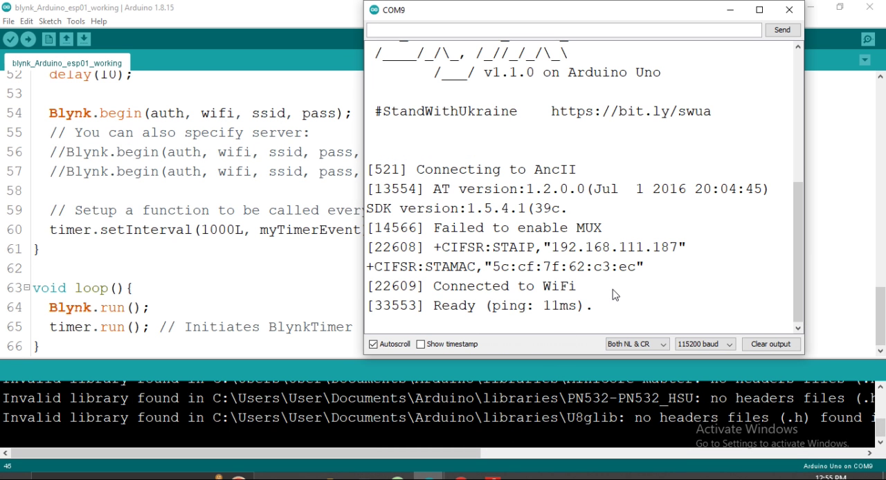
The serial monitor printing show that the ESP-01 is connected to the WiFi network and it has successfulyl made a handshake with the Blynk IoT dashboard. We can measure or take the reading of our DC Voltage reading via the Analog pins on the Arduino, using the Serial Monitor on the Arduino IDE. Depending on the Power supply (which are mostly DC Voltage connected to the Output of the Voltage Sensor).
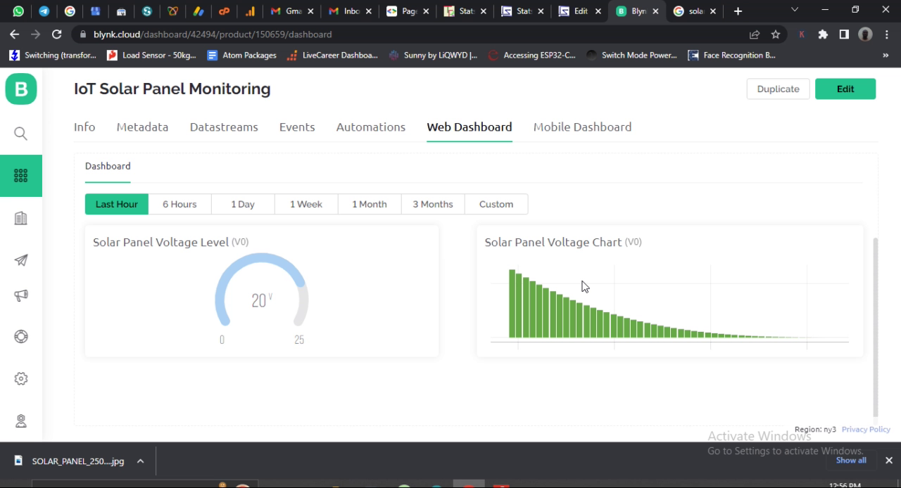
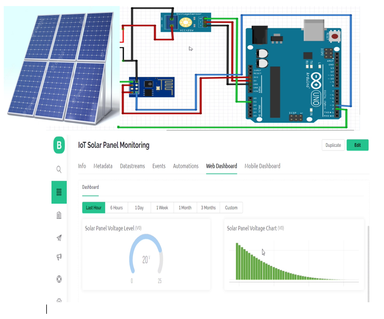
When it is being tested, we can see the measured voltage of the PV panel displayed on the voltage widget as shown above. The PV panel at the moment being indoors was only harvesting 20V DC as measure by the voltage sensor module. And we could see the measured voltage over time on the bar char displayed on the right hand side.
Conclusion
The project tutorial for IoT Based Solar Panel Monitoring using Arduino Voltage Sensor Module has been shown to be successful. We have been able to measure C voltage using the Voltage sensor module and Arduino Uno baord, and using the ESP-01, exported the read voltage data to the Blynk IoT dashboard where we could monitor the setup remotely form anywhere in the world. Let us know if you followed these step mentioned in this blog post to achieved the same value in the comment section below.

