The project design IoT Irrigation System With NPK Sensor, details the design and implementation of an internet of things irrigation system prototype that uses an ESP8266-12E (NodeMCU), NPK sensor, digital humidity and temperature sensor DHT22, and an underground Dallas temperature sensor DS18B20, etc. to monitor the soil nitrogen, potassium, and phosphate levels, perform artificial irrigation, monitor humidity and temperature, as well as the aeration of the soil. We will monitor and display all these parameters on the Cayenne IoT Dashboard. Ensure to read until the end of the blog post to get step-by-step instructions on how this was done.
Kindly like, subscribe and share our video to encourage us to keep making such videos. Thank you.
Components Needed for This Project
| Components | Quantity |
|---|---|
| NodeMCU board | 1 |
| DS18B20 waterproof sensor | 1 |
| 4.7k Resistor | 1 |
| NPK Sensor | 1 |
| 12V power supply | 1 |
| DC-DC buck converter module | 1 |
| 5V (or 12V) DC pump | 1 |
| DHT22 sensor module | 1 |
| TIP41C transistor | 1 |
| 3×6″ casing box | 1 |
| Single channel relay module | 1 |
| LED, 22 Ohm resistors | 1 |
IoT Irrigation System With NPK Sensor – The Circuit Diagram
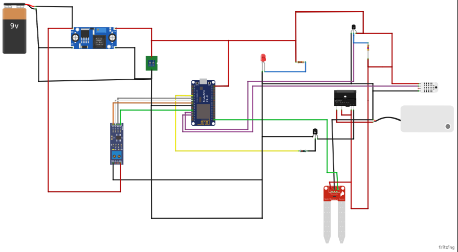
The schematic diagram of the project design is shown above. You can download the PDF copy from my GitHub repository here. DOWNLOAD THE PDF HERE.
Explanation of The Circuit Diagram
The circuit diagram uses the NodeMCU board to read all the sensors connected to it. The Dallas temperature sensor uses a 4.7K resistor that is connected between its data pinout and the Vcc pin. And this is connected to the GPIO pin on the NodeMCU board. The soil moisture sensor is connected to the analog pin A0 on the NodeMCU board, while the Max485 module is used to read the NPK sensor and is connected to the 4 GPIO pins of the NodeMCU. We used the DHT22 sensor to sense the digital humidity and temperature of the atmosphere. The pump is connected to a single channel relay, and this will control the turning on and turning off of the DC pump, hence the irrigation of the soil. We used an LED indicator to show when the system was powered on.
PLEASE NOTE THAT THE NPK SENSOR IS CONNECTED TO THE MAX485 MODULE. The A and B pinouts are connected to the sensor data cables.
Programming the IoT Irrigation System With NPK Sensor
//Lets start by importing the neccesary libraries to aid our code.
#include <EEPROM.h>
#include <Wire.h>
#include <SoftwareSerial.h> //Import library for using additional UART pins
#include "DHT.h"
#include <DallasTemperature.h>
#include <OneWire.h>


//#define CAYENNE_DEBUG
#define CAYENNE_PRINT Serial
#include <CayenneMQTTESP8266.h>

#define DHTPIN D2     // Digital pin connected to the DHT sensor
#define ONE_WIRE_BUS D4  //D4 pin of nodemcu
//Declare where the pump Pin is connected
#define pumpPin D3
#define VIRTUAL_CHANNEL 7
//#define DHTTYPE DHT11   // DHT 11
#define DHTTYPE DHT22   // DHT 22  (AM2302), AM2321
//#define DHTTYPE DHT21   // DHT 21 (AM2301)

#define RE D7
#define DE D6
#define DI D5
#define RO D8


int sensorPin = A0;

//const byte code[]= {0x01, 0x03, 0x00, 0x1e, 0x00, 0x03, 0x65, 0xCD};
const byte nitro[] = {0x01,0x03, 0x00, 0x1e, 0x00, 0x01, 0xe4, 0x0c};
const byte phos[] = {0x01,0x03, 0x00, 0x1f, 0x00, 0x01, 0xb5, 0xcc};
const byte pota[] = {0x01,0x03, 0x00, 0x20, 0x00, 0x01, 0x85, 0xc0};

byte values[11];
SoftwareSerial mod(RO, DI);

int sensorValue;
float temp, hum, soilTemp;
OneWire oneWire(ONE_WIRE_BUS);
DallasTemperature sensors(&oneWire);  // Pass the oneWire reference to Dallas Temperature.

DHT dht(DHTPIN, DHTTYPE);

boolean buttonState = true;
int iotButton;


// WiFi network info.
char ssid[] = "AncII";
char wifiPassword[] = "eureka26";

// Cayenne authentication info. This should be obtained from the Cayenne Dashboard.
char username[] = "00d420d0-cfbe-11eb-8779-7d56e82df461";
char password[] = "b72281be1c7d94c9d604963032cabbd20cedbcbd";
char clientID[] = "0ba03010-a1b6-11ec-a681-73c9540e1265";


void setup() {
   Serial.begin(9600);
  Serial.begin(115200);// initialize UART protocol at a speed of 115200 baud rate.
  Cayenne.begin(username, password, clientID, ssid, wifiPassword);
  mod.begin(9600);
  pinMode(RE, OUTPUT);
  pinMode(DE, OUTPUT);
  Serial.println(F("DHTxx test!"));
  dht.begin();
  sensors.begin();
   pinMode(sensorPin, INPUT);
  pinMode(pumpPin, OUTPUT);
   digitalWrite(pumpPin, LOW);
   delay(4000);

}


float soilTempSensor(int port){
  sensors.requestTemperatures();        // Send the command to get temperatures
  soilTemp = sensors.getTempCByIndex(port);
  Serial.print("soil Temp: ");   // Why "byIndex"? You can have more than one IC on the same bus. 0 refers to the first IC on the wire
Serial.println(soilTemp);
return soilTemp;
}

float dhtSensor(){
   // Wait a few seconds between measurements.
  delay(2000);
  // Reading temperature or humidity takes about 250 milliseconds!
  // Sensor readings may also be up to 2 seconds 'old' (its a very slow sensor)
   hum = dht.readHumidity();
  // Read temperature as Celsius (the default)
   temp = dht.readTemperature();
  // Read temperature as Fahrenheit (isFahrenheit = true)
  float f = dht.readTemperature(true);
  // Check if any reads failed and exit early (to try again).
  if (isnan(hum) || isnan(temp) || isnan(f)) {
    Serial.println(F("Failed to read from DHT sensor!"));
    return 0;
  }
  // Compute heat index in Fahrenheit (the default)
  float hif = dht.computeHeatIndex(f, hum);
  // Compute heat index in Celsius (isFahreheit = false)
  float hic = dht.computeHeatIndex(temp, hum, false);

return hum, temp;
}


int readMoistLevel(int timeWait, int sensorPin){
  // read the input on analog pin 0:
sensorValue = analogRead(sensorPin);
  //map the vlaue gotten from 1 to 100
  sensorValue = map(sensorValue, 0, 1023, 100, 0);
  //constrain the value only 1 to 100
  //sensorValue = constrain(sensorValue, 0, 100);
  sensorValue = map(sensorValue, 28, 73, 0, 100);
  //if the value is still between 1 to 10, multiply by a factor of 10
  //sensorValue *= 10;
  // print out the value you read:
  Serial.print("Soil Moisture ");
  Serial.println(sensorValue);
  delay(timeWait);        // delay in between reads for stability
  return sensorValue;
}


byte nitrogen(){
  digitalWrite(DE,HIGH);
  digitalWrite(RE,HIGH);
  delay(10);
  if(mod.write(nitro,sizeof(nitro))==8){
    digitalWrite(DE,LOW);
    digitalWrite(RE,LOW);
    for(byte i=0;i<7;i++){
    //Serial.print(mod.read(),HEX);
    values[i] = mod.read();
    Serial.print(values[i],HEX);
    }
    Serial.println();
  }
  return values[4];
}

byte phosphorous(){
  digitalWrite(DE,HIGH);
  digitalWrite(RE,HIGH);
  delay(10);
  if(mod.write(phos,sizeof(phos))==8){
    digitalWrite(DE,LOW);
    digitalWrite(RE,LOW);
    for(byte i=0;i<7;i++){
    //Serial.print(mod.read(),HEX);
    values[i] = mod.read();
    Serial.print(values[i],HEX);
    }
    Serial.println();
  }
  return values[4];
}

byte potassium(){
  digitalWrite(DE,HIGH);
  digitalWrite(RE,HIGH);
  delay(10);
  if(mod.write(pota,sizeof(pota))==8){
    digitalWrite(DE,LOW);
    digitalWrite(RE,LOW);
    for(byte i=0;i<7;i++){
    //Serial.print(mod.read(),HEX);
    values[i] = mod.read();
    Serial.print(values[i],HEX);
    }
    Serial.println();
  }
  return values[4];
}


void loop() {
  Cayenne.loop();
  //call the fxn to return the soil moisture sensor
 readMoistLevel(100, sensorPin);
 soilTempSensor(0);
 dhtSensor();

byte val1,val2,val3;
  val1 = nitrogen();
  delay(250);
  val2 = phosphorous();
  delay(250);
  val3 = potassium();
  delay(250);


Serial.print("Nitrogen: ");
  Serial.print(val1);
  Serial.println(" mg/kg");
  Serial.print("Phosphorous: ");
  Serial.print(val2);
  Serial.println(" mg/kg");
  Serial.print("Potassium: ");
  Serial.print(val3);
  Serial.print(" mg/kg");
 Serial.print(F("Humidity: "));
  Serial.print(hum);
  Serial.print(F("%  Temperature: "));
  Serial.print(temp);
  Serial.println(F("°C "));
 }


CAYENNE_IN(VIRTUAL_CHANNEL){
int value = getValue.asInt();
  CAYENNE_LOG("Channel %d, pin %d, value %d", VIRTUAL_CHANNEL, pumpPin, value);
  // Write the value received to the digital pin.
  digitalWrite(pumpPin, value);

   }


CAYENNE_OUT_DEFAULT(){
  //call the fxn to return the soil moisture sensor
 readMoistLevel(100, sensorPin);
 soilTempSensor(0);
 dhtSensor();

byte val1,val2,val3;
  val1 = nitrogen();
  delay(250);
  val2 = phosphorous();
  delay(250);
  val3 = potassium();
  delay(250);


Cayenne.celsiusWrite(0, soilTemp);
Cayenne.celsiusWrite(1, hum);
Cayenne.celsiusWrite(2, temp);
Cayenne.celsiusWrite(3, sensorValue);
Cayenne.celsiusWrite(4, val1);
Cayenne.celsiusWrite(5, val2);
Cayenne.celsiusWrite(6, val3);

//
if(sensorValue < 11){
    buttonState = false;
    digitalWrite(pumpPin, HIGH);
     }

 //
 if(sensorValue >= 97){
      buttonState = true;
    digitalWrite(pumpPin, LOW);
      }

//
if((sensorValue >= 12)&&(sensorValue <=90)){
  if(buttonState == true){
  CAYENNE_IN(VIRTUAL_CHANNEL);
 }
}
}
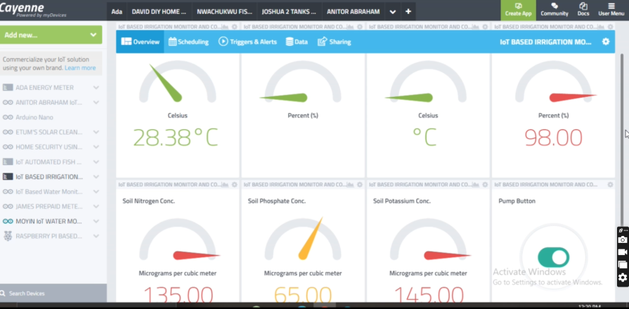
Setting Up The Cayenne Dashboard
Watch the YouTube video to see how to set this project up on the Cayenne dashboard. It is an easy and straightforward way. If you happen to run into any difficulties, kindly let us know in the comment section below.
The dashboard was designed to have the soil temperature, the atmospheric temperature, the atmospheric humidity, the soil nitrogen concentration, the soil phosphate concentration, and the potassium concentration. And a user button was included to energize the underground pump to start irrigation of the soil when the soil moisture level was low. The user can also see the soil water or moisture level on the dashboard.
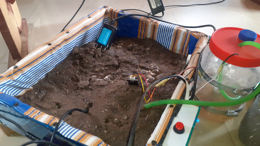
Assembling The Components Together
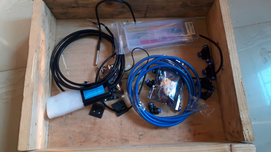
To model the project prototype, we needed to display the artificial irrigation system in a model box. We used a wooden container like the one shown above. The project was first physically assembled and tested on a breadboard using some pre-formed jumper wires.
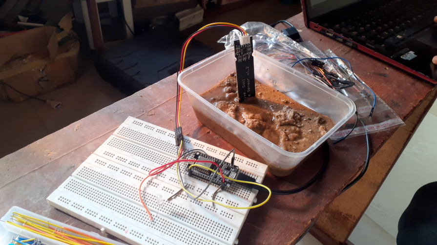
The NodeMCU was connected to the sensors, and the Arduino sketch was tested to see if it is working. The capacitive soil moisture sensor was tested and calibrated according to the needs of the project before its final connection.
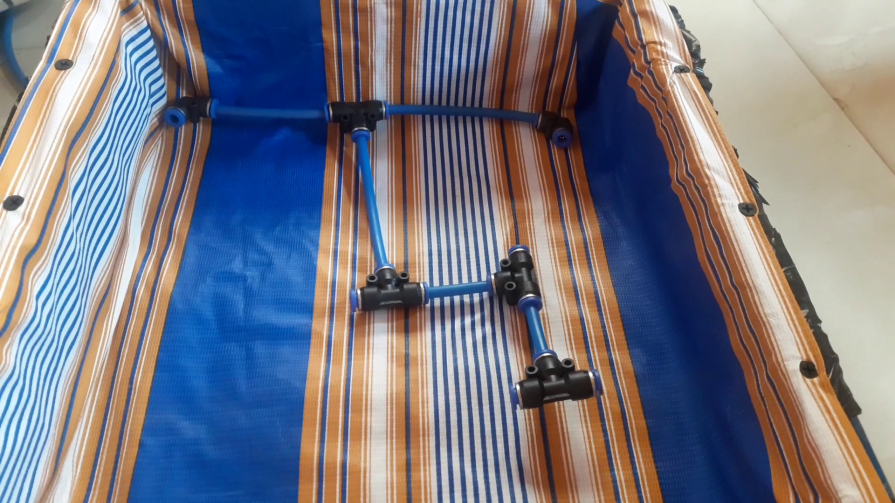
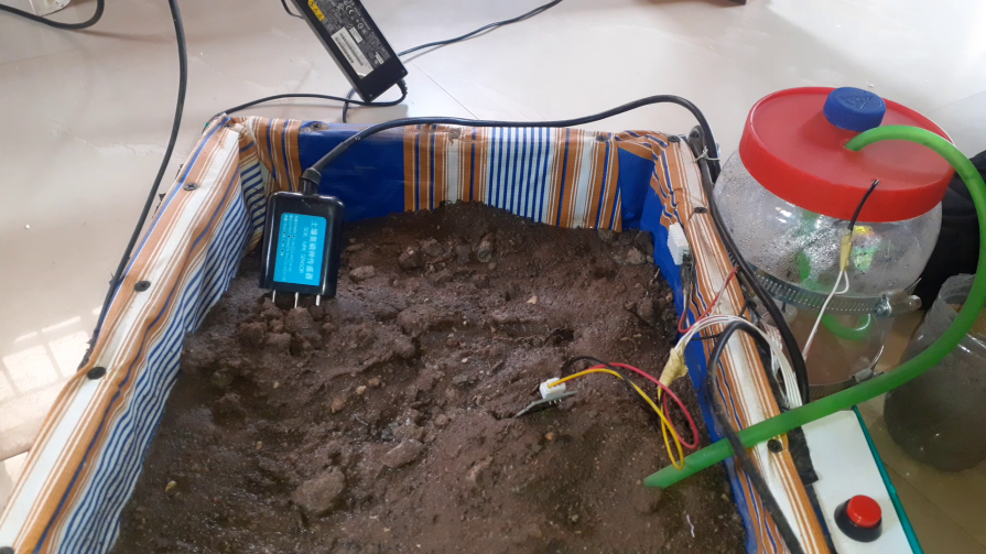
The model irrigation box interior was wrapped with polyethylene wrapping materials layered three times to ensure the water didn’t escape, and the underground hose was run as shown above. These hose networks have open ends, and this would be where the water would leak out once soil was placed on them.
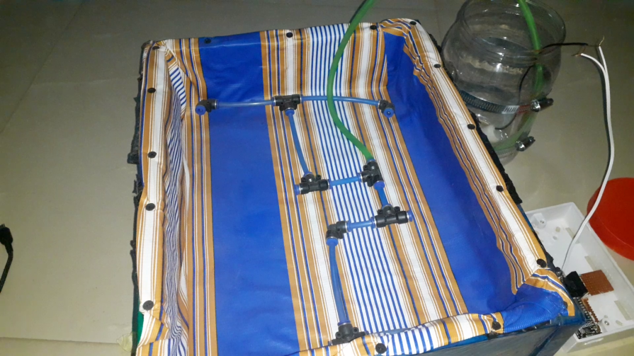
This was tested first and found to work as planned. The next phase was to actually place the soil and finish the assembly. We placed the 5V DC pump into the reserve container and made the necessary connections.
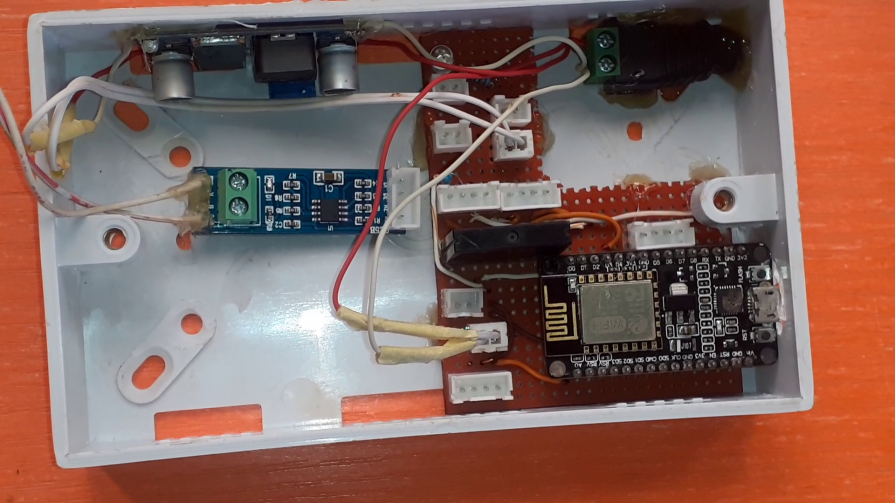
The circuitry was encased in this small 3×6″ box. The rest of the connection was covered using PCB header sockets. We used the DC-DC buck converter to buck 5V for the NodeMCU and the sensors since they operate on 5V logic.
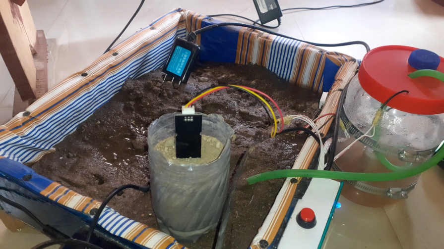
Testing The Project
The project design was tested as shown above. When the soil moisture sensor is placed in a dry soil, the pump will start irrigating the soil, and when it is placed back in wet and fully irrigated soil, it will stop pumping water into the soil.
Conclusion
We have designed and implemented an IoT Irrigation System With NPK Sensor using the Arduino IDE and Cayenne IoT platform. It has worked for us, and we would like to know if you followed the steps outlined in this blog or even made some modifications to achieve yours. Leave us a review in the comments below.

