In this tutorial, we will be going through how to design and construct an Arduino classroom attendance counter with an ESP32 Cam and Arduino IDE. The project design would use the ESP32 Cam development board to stream real-time video surveillance of a classroom. Also record the classroom attendance by counting the number of students inside the class through the entrance door and the number of students who have left the classroom through the exit door. This counting is very possible using infrared (IR) proximity sensors that is placed at the two doors of the project design. In summary, we will be achieving the following objectives:
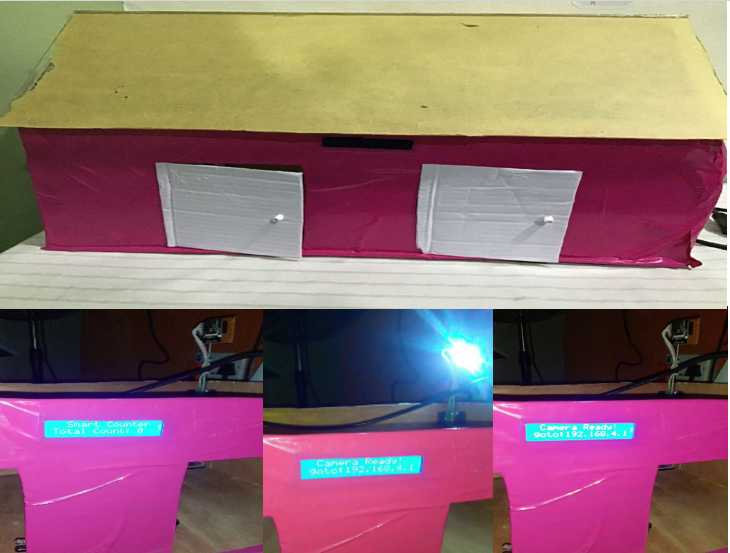
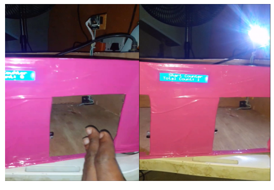
- Using Infrared proximity sensors placed at the doors to check for entry attendance and exit attendance of “model” students. The exit attendance is subtracted from the entry attendance and this was termed as the total count or head count in the classroom. This was displayed on a smart LCD screen at the front view of the model classroom.
- The system design checked for two importance cases; namely when the total count was equal to zero and when it was above zero. During the latter scenario, the design would trigger on an actuator which was a bright light onboard the ESP32 Cam to brighten up the model classroom. During the former, the project would turn off the bight LED light since there was no model student in the model classroom anymore.
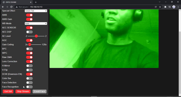
- The project design allowed one user to stream seamlessly in real time the surveillance video of the vicinity of the model classroom. This was achieved by some HTML (hypertext markup language), JavaScript and CSS (cascading style sheet) that was run on the SoC (system on Chip) memory of the ESP32 Dev board. This provide an easy to use UI (user interface) that was accessed by logging the IP address of the A.P network the user was already connected to.
- The UI has many functionalities that allowed the use of different view point angles, contrast and light features. It also provided buttons to take pictures, stream and stop video streaming etc.
Materials for this Project Design
- ESP32 Cam Development Board…1 Pieces
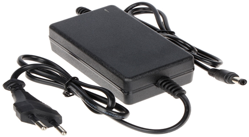
- 0.4A 5V Hi-link Power Supply…1 pieces
- Infrared (IR) Promixity sensor..2 pieces
- 1602 LCD module
- I2C LCD module
- Veroboard
- Male and Female header pin
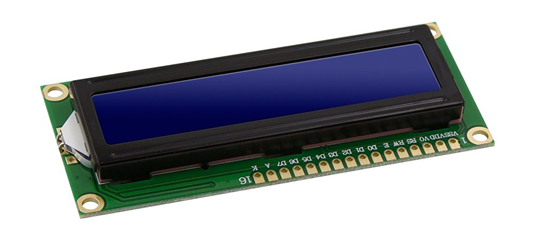
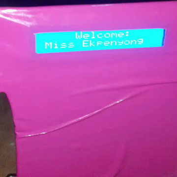
The LCD module is a Hitachi 16×2 liquid crystal display. This means it can display 16 characters on the vertical orientation and 2 rows of these vertical characters. The LCD screen type was picked to be blue color. We used this to know what is going on with the Arduino board. On startup, the screen would display the project title and show position of the action buttons.
Technical Specifications
- 16 character x 2 line Blue LCD
- 4-bit and 8-bit parallel interface
- DC Power Input 5V nominal (5.5V max)
- Operating Current (Total) 30mA (typical)
- Operating Current (Backlight Only) 20mA (typical)
The Power Supply
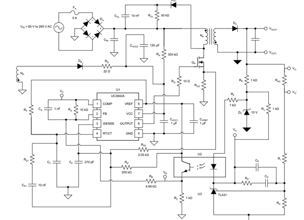
The circuit diagram shows an output of 5V DC at 3A current rating. A power diode is put in series to its DC output to stop feedback voltage from the connected load. The MOSFET QA is used to switch the KA3842 depending on the amount of current the load needs at 12V.
Unlike the traditional linear power supply, the power supply was able to maintain stable 5V at 3A current supply when the AC input supply suddenly goes high above the rated 220V AC (transient). This was the same result when there is a voltage drop in the AC to about 100V AC, the MOSFET was driven to increase the frequency across the fly-back converter and this increased the wave form and hence there was stable supply of 5V output.
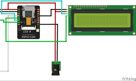
The Schematic Diagram of IoT Classroom Attendance Surveillance System
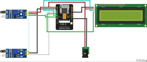
Circuit Diagram Explanation
The project design used ESP32 Cam microcontroller in accomplishing its sets objective of Local Area Network (LAN) surveillance and total digital counting of attendance. As shown in the breadboard view of the schematic diagram above; The system used a power jack to accept 5V DC supply from the external power supply adapter.
The project design has a microcontroller esp32 development board running the function of taking “still” pictures of about 1000 times in one second and streaming this on a webserver over LAN. This would form a video surveillance for streaming. This also allowed the user to count The IR signals detect at each door.
Programming the LCD Module
The LCD module is connected using the 2-bit or 2 wire data communication protocol. This means that we connected on 2 wires the SDA (serial data) and SCL (serial clock) to the ESP32 Cam board. Also, 10kΩ potentiometer output pin on board the I2C module was connected to the A0 of the LCD to adjust its contrast level. While its Vcc and Gnd pins are connected to 5V respectively.
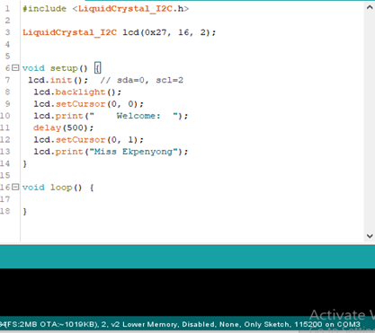
Program Code for LCD
The program code for Arduino classroom counter project shown in the code snippet below was used to display a welcome message and also further display other commands and events that took place in the brain of the project the ESP32 Cam. The program code was in C++ language and was coded and complied in the Arduino IDE (integrated development environment). The library used was the Inter-integrated Circuit (I2C) module library that allowed us to use only 2 wires for communication access to the LCD inside of 4 wires or 8 wires
Programming the Infrared (IR) Proximity Sensors
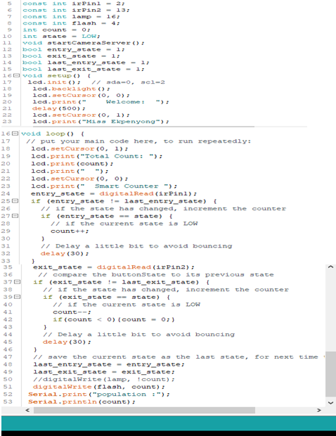
The code snippet in fig 4.5 began with calling the I2C library in code line 1. The type of LCD module used was outline in code line 2 as well as the LCD’s Hex code. The first program function setup() had the start LCD I2C module start up using code line 7 and the LCD backlight was turned on in code line 8. Where we wanted the LCD to start printing the string characters was initiated in code line 8 using syntax lcd.setCursor(0,0). This means that the string character could begin in row 1 and column 1. Since computer starts counting from zero. The welcome message was printed after this. In the loop() function, the IR modules were read from their data-out pins declared in code line 5 and 6 respectively. And the signals were and saved in the variables declared in 9 through 10. The count calculations was best put in the loop() function because the function would repeatedly executes the codes inside it.
Code line 25 through 49 used if statement logic calculations to check the state of the IR proximity sensor modules and and count in the increment direction if the total number of persons through the entry door surpassed that of the number of of persons through the exit door. The if statement also check for when the “count” is above zero (0) so that it can turn on the LED bright light. On the other hand, another if else state check when exactly the “count” is zero (0) so that it can turn off the same LED bright light. All these are displayed on the LCD screen using code line 18 through 23.
Arduino Classroom Counter: Arduino Sketch
#include "esp_camera.h"
#include <WiFi.h>
#include <Wire.h>
#include <LiquidCrystal_I2C.h>

#define CAMERA_MODEL_AI_THINKER

#include "camera_pins.h"

LiquidCrystal_I2C lcd(0x27, 16, 2);
const char* ssid = "Ekpenyong-CAM";
const char* password = "1234567890";
const int irPin1 = 2;
const int irPin2 = 13;
const int flash = 4;
int count = 0;
int state = LOW;
void startCameraServer();
bool entry_state = 1;
bool exit_state = 1;
bool last_entry_state = 1;
bool last_exit_state = 1;

void setup() {
pinMode(irPin1, INPUT_PULLUP);
pinMode(irPin2, INPUT_PULLUP);
pinMode(flash, OUTPUT);
digitalWrite(flash, 0);
  Serial.begin(115200);
  Serial.setDebugOutput(true);
  Serial.println();
  camera_config_t config;
  config.ledc_channel = LEDC_CHANNEL_0;
  config.ledc_timer = LEDC_TIMER_0;
  config.pin_d0 = Y2_GPIO_NUM;
  config.pin_d1 = Y3_GPIO_NUM;
  config.pin_d2 = Y4_GPIO_NUM;
  config.pin_d3 = Y5_GPIO_NUM;
  config.pin_d4 = Y6_GPIO_NUM;
  config.pin_d5 = Y7_GPIO_NUM;
  config.pin_d6 = Y8_GPIO_NUM;
  config.pin_d7 = Y9_GPIO_NUM;
  config.pin_xclk = XCLK_GPIO_NUM;
  config.pin_pclk = PCLK_GPIO_NUM;
  config.pin_vsync = VSYNC_GPIO_NUM;
  config.pin_href = HREF_GPIO_NUM;
  config.pin_sscb_sda = SIOD_GPIO_NUM;
  config.pin_sscb_scl = SIOC_GPIO_NUM;
  config.pin_pwdn = PWDN_GPIO_NUM;
  config.pin_reset = RESET_GPIO_NUM;
  config.xclk_freq_hz = 10000000;
  config.frame_size = FRAMESIZE_UXGA;
  config.pixel_format = PIXFORMAT_JPEG; // for streaming
  //config.pixel_format = PIXFORMAT_RGB565; // for face detection/recognition
  config.grab_mode = CAMERA_GRAB_WHEN_EMPTY;
  config.fb_location = CAMERA_FB_IN_PSRAM;
  config.jpeg_quality = 10;
  config.fb_count = 1;

  // if PSRAM IC present, init with UXGA resolution and higher JPEG quality
  //                      for larger pre-allocated frame buffer.
  if(config.pixel_format == PIXFORMAT_JPEG){
    if(psramFound()){
      config.jpeg_quality = 10;
      config.fb_count = 2;
      config.grab_mode = CAMERA_GRAB_LATEST;
    } else {
      // Limit the frame size when PSRAM is not available
      config.frame_size = FRAMESIZE_SVGA;
      config.fb_location = CAMERA_FB_IN_DRAM;
    }
  } else {
    // Best option for face detection/recognition
    config.frame_size = FRAMESIZE_240X240;
#if CONFIG_IDF_TARGET_ESP32S3
    config.fb_count = 2;
#endif
  }
  // camera init
  esp_err_t err = esp_camera_init(&config);
  if (err != ESP_OK) {
    Serial.printf("Camera init failed with error 0x%x", err);
    return;
  }

  sensor_t * s = esp_camera_sensor_get();
  // initial sensors are flipped vertically and colors are a bit saturated
  if (s->id.PID == OV3660_PID) {
    s->set_vflip(s, 1); // flip it back
    s->set_brightness(s, 1); // up the brightness just a bit
    s->set_saturation(s, -2); // lower the saturation
  }
  // drop down frame size for higher initial frame rate
  if(config.pixel_format == PIXFORMAT_JPEG){
    s->set_framesize(s, FRAMESIZE_QVGA);
  }

#if defined(CAMERA_MODEL_M5STACK_WIDE) || defined(CAMERA_MODEL_M5STACK_ESP32CAM)
  s->set_vflip(s, 1);
  s->set_hmirror(s, 1);
#endif

#if defined(CAMERA_MODEL_ESP32S3_EYE)
  s->set_vflip(s, 1);
#endif

  lcd.init();  // sda=0, scl=2
  lcd.backlight();
  lcd.setCursor(0, 0);
  lcd.print("    Welcome:  ");
  delay(500);
  lcd.setCursor(0, 1);
  lcd.print("Miss Ekpenyong");
  delay(3000);
  WiFi.softAP(ssid, password);
  WiFi.setSleep(false);
  IPAddress IP = WiFi.softAPIP();
  String myIP = IP.toString();
  Serial.print("AP IP address: ");
  Serial.println(myIP);

  startCameraServer();

  Serial.print("Camera Ready! Use 'http://"+myIP);
  Serial.println("' to connect");
  lcd.setCursor(0, 0);
  lcd.print(" Camera Ready!  ");
  delay(500);
  lcd.setCursor(0, 1);
  lcd.print("goto:"+myIP);
  digitalWrite(flash, 1);
  delay(500);
  digitalWrite(flash, 0);
  delay(500);
  digitalWrite(flash, 1);
  delay(500);
  digitalWrite(flash, 0);
  delay(500);
  digitalWrite(flash, 1);
  delay(3500);
  digitalWrite(flash, 0);
  delay(500);
}

void loop() {
  // put your main code here, to run repeatedly:
  lcd.setCursor(0, 1);
  lcd.print("Total Count: ");
  lcd.print(count);
  lcd.print("  ");
  lcd.setCursor(0, 0);
  lcd.print("  Smart Counter ");
  entry_state = digitalRead(irPin1);
  if (entry_state != last_entry_state) {
    // if the state has changed, increment the counter
    if (entry_state == state) {
      // if the current state is LOW
      count++;
    }
    // Delay a little bit to avoid bouncing
    delay(30);
  }

  exit_state = digitalRead(irPin2);
   // compare the buttonState to its previous state
  if (exit_state != last_exit_state) {
    // if the state has changed, increment the counter
    if (exit_state == state) {
      // if the current state is LOW
      count--;
      if(count < 0){count = 0;}
    }
    // Delay a little bit to avoid bouncing
    delay(30);
  }
  // save the current state as the last state, for next time through the loop
  last_entry_state = entry_state;
  last_exit_state = exit_state;
  //digitalWrite(lamp, !count);
  digitalWrite(flash, count);
 Serial.print("population :");
 Serial.println(count);
}
Conclusion
The project, Arduino classroom counter design has been designed, programmed, assembled and constructed. It has achieved the aims and objectives within its scope of design. It has been able to do the above mentioned objectives successfully. Let us know what you think about this project design in the comment section.

