Fire detection and video surveillance are two important security measures that can help protect your home or business. Fire detection systems can alert you to a fire in its early stages, when it is still small and easy to extinguish. Video surveillance systems can help you identify where the fire is coming from, even from remote places. This project design uses a flame sensor module to detect when there is a fire incident in a place. A smoke sensor module to detect if there is gas leakage that could start a potential fire or kill people, and a PIR motion sensor to detect motion. The ESP32 Cam shows in real time the video surveillance of the fire, which is very useful for firefighters. The project also has an IoT dashboard, where these sensors can trigger a notification alert to your email or phone as SMS texts when there are such incidents. Let us learn how to design fire detection and video surveillance project step-by-step, ensure you read until the end.
Components/Materials Needed for Fire Detection And Video Surveillance Project
| Components | Quantity |
|---|---|
| ESP32 Cam | 1 |
| PIR Motion Sensor | 1 |
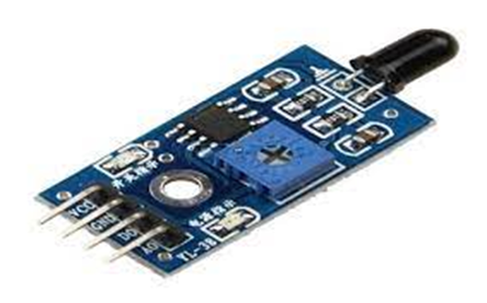
| Flame Sensor Module | 1 |
| MQ2 Gas Sensor Module | 1 |
| Header pin (male and female type) | 3 pieces each |
| Plywood board | 1 |
| Connectors and PVC wrapper | 1 |
The components for this project design is listed in table above. The components ( you can order from our online store) are quite inexpensive and can be assembled together in less than 3 hours. It requires minimum craftmanship and the more stylish you want it, it works very well on your creativity.
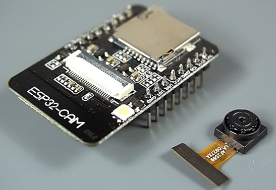
The ESP32-CAM board is a low cost DIY microcontroller with 2MP camera. It combines the ESP32 chip from Exxpressif commay and a cameral with model OV2640. We used this device to read our sensors and also set up a real life surveillance to monitor the live feed from our design (model home).
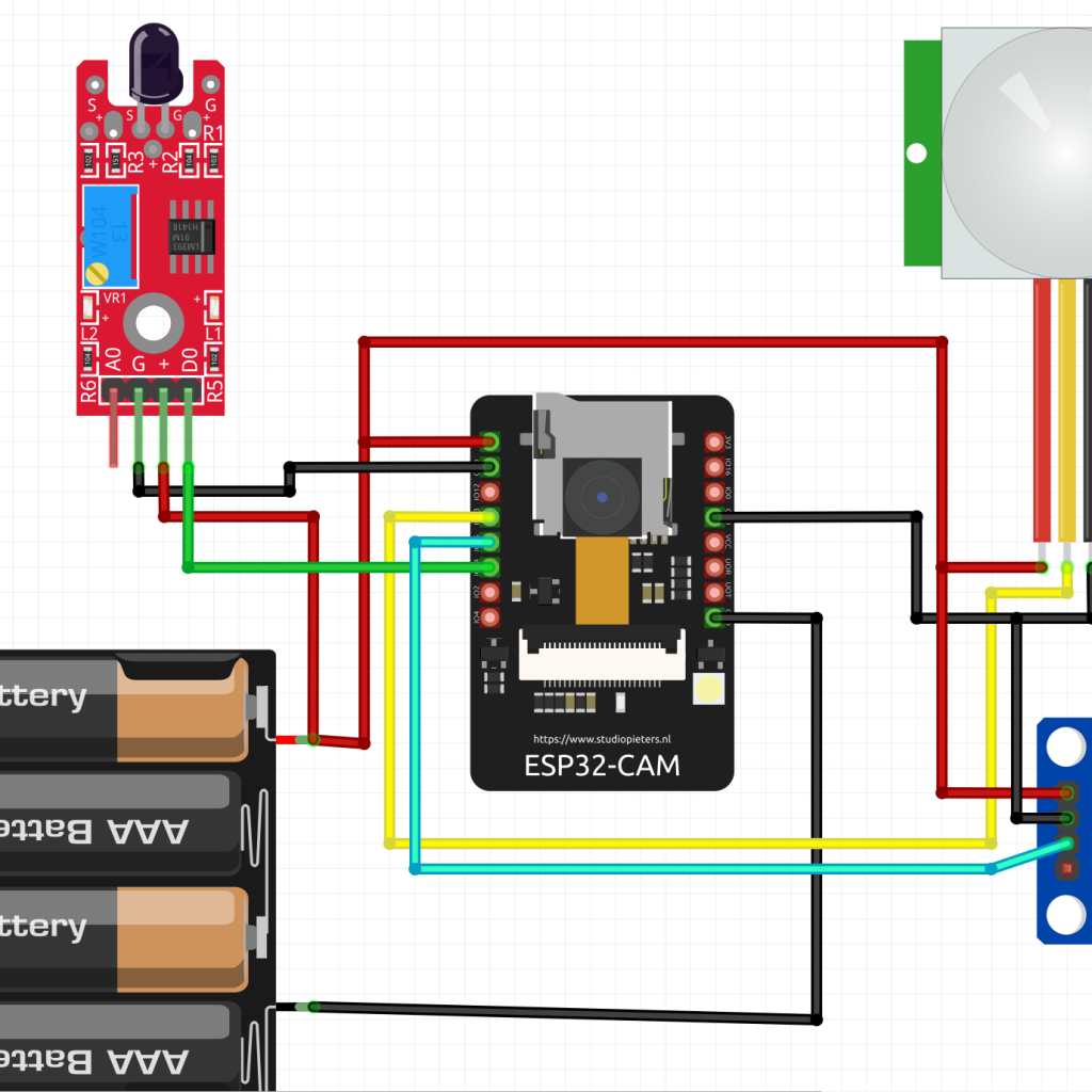
How to Design Fire Detection And Video Surveillance Project: The Schematic Diagram
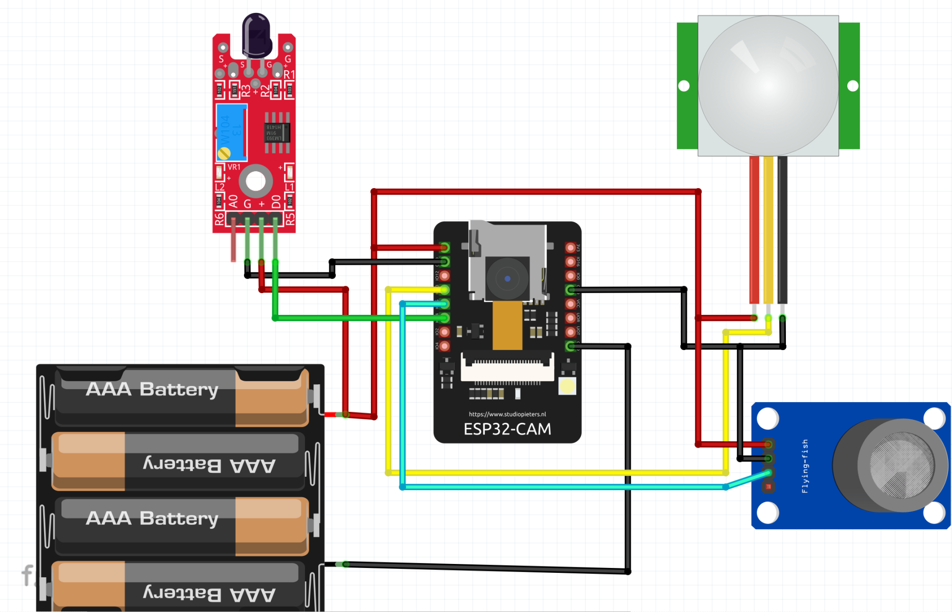
The circuit diagram above, show that the modules are connected to the ESP32 Cam development board. It uses the 12-bit ADC pin of this board to read the analog pinout of the flame sensor and the MQ2 gas sensor modules. This makes it very possible to check for when there is elevated levels of dangerous gas like methane that could kill as well as ignite fire.
The PIR motion sensor is connected directly to any of the GPIO pins of the ESP32 Cam board that could read digital IO. We can sense the PIR pinout go HIGH when there is motion and LOW when there isn’t any. The PIR motion sensor module gives a logic voltage of 3.3V hence there is no need to worry about voltage shifting. All the modules connected to the ESP32 Cam board was given the 5V DC from a 5V USB power rail. This can be readily sourced form a phone adapter or charger.
The ESP32 Cam would be able to create a local host network (LAN) where a user can connect to via WiFi and stream in real time the video surveillance feed. It will also be able to connect to an existing WiFI network that has internet access so that it can remotely broadcast the sensors read data to an IoT platform that would trigger SMS and emails when the sensors are tripped.
Setting Up IoT Dashboard For The Project Design

The IoT dashboard was designed on Cayenne mydevices platform. It has three (3) dominant widgets that would show color changes when the sensors perceived anomaly in the environment when the devices was placed. The individual widget was configured to send an email alert to a particular mailbox when the data on them exceeded a particular level.
Arduino Source Code for Fire Detection And Video Surveillance
#include "esp_camera.h"
#include <WiFi.h>
//#define CAYENNE_DEBUG
#define CAYENNE_PRINT Serial
#include <CayenneMQTTESP32.h>
//
// WARNING!!! Make sure that you have either selected ESP32 Wrover Module,
//            or another board which has PSRAM enabled
//

// Select camera model
//#define CAMERA_MODEL_WROVER_KIT
//#define CAMERA_MODEL_ESP_EYE
//#define CAMERA_MODEL_M5STACK_PSRAM
//#define CAMERA_MODEL_M5STACK_WIDE
#define CAMERA_MODEL_AI_THINKER

#include "camera_pins.h"

// WiFi network info.
char ssid[] = "Smartech";
char wifiPassword[] = "1234567890";
// Cayenne authentication info. This should be obtained from the Cayenne Dashboard.
char username[] = "00d420d0-cfbe-11eb-8779-7d56e82df461";
char password[] = "b72281be1c7d94c9d604963032cabbd20cedbcbd";
char clientID[] = "057d8f80-d5af-11eb-b767-3f1a8f1211ba";

#define MOTION_PIN 13 // Do not use digital pins 0 or 1 since those conflict with the use of Serial.
#define FLAME_PIN 14
#define SMOKE_PIN 15
#define MOTION_CHANNEL 2
#define FLAME_CHANNEL 3
#define SMOKE_CHANNEL 4

unsigned long lastMillis = 0;

void startCameraServer();

void setup() {
  Serial.begin(115200);
  pinMode(MOTION_PIN, INPUT);
  pinMode(FLAME_PIN, INPUT);
  pinMode(SMOKE_PIN, INPUT);
  Serial.setDebugOutput(true);
  Serial.println();

  camera_config_t config;
  config.ledc_channel = LEDC_CHANNEL_0;
  config.ledc_timer = LEDC_TIMER_0;
  config.pin_d0 = Y2_GPIO_NUM;
  config.pin_d1 = Y3_GPIO_NUM;
  config.pin_d2 = Y4_GPIO_NUM;
  config.pin_d3 = Y5_GPIO_NUM;
  config.pin_d4 = Y6_GPIO_NUM;
  config.pin_d5 = Y7_GPIO_NUM;
  config.pin_d6 = Y8_GPIO_NUM;
  config.pin_d7 = Y9_GPIO_NUM;
  config.pin_xclk = XCLK_GPIO_NUM;
  config.pin_pclk = PCLK_GPIO_NUM;
  config.pin_vsync = VSYNC_GPIO_NUM;
  config.pin_href = HREF_GPIO_NUM;
  config.pin_sscb_sda = SIOD_GPIO_NUM;
  config.pin_sscb_scl = SIOC_GPIO_NUM;
  config.pin_pwdn = PWDN_GPIO_NUM;
  config.pin_reset = RESET_GPIO_NUM;
  config.xclk_freq_hz = 20000000;
  config.pixel_format = PIXFORMAT_JPEG;
  //init with high specs to pre-allocate larger buffers
  if(psramFound()){
    config.frame_size = FRAMESIZE_UXGA;
    config.jpeg_quality = 10;
    config.fb_count = 2;
  } else {
    config.frame_size = FRAMESIZE_SVGA;
    config.jpeg_quality = 12;
    config.fb_count = 1;
  }

#if defined(CAMERA_MODEL_ESP_EYE)
  pinMode(13, INPUT_PULLUP);
  pinMode(14, INPUT_PULLUP);
#endif

  // camera init
  esp_err_t err = esp_camera_init(&config);
  if (err != ESP_OK) {
    Serial.printf("Camera init failed with error 0x%x", err);
    return;
  }

  sensor_t * s = esp_camera_sensor_get();
  //initial sensors are flipped vertically and colors are a bit saturated
  if (s->id.PID == OV3660_PID) {
    s->set_vflip(s, 1);//flip it back
    s->set_brightness(s, 1);//up the blightness just a bit
    s->set_saturation(s, -2);//lower the saturation
  }
  //drop down frame size for higher initial frame rate
  s->set_framesize(s, FRAMESIZE_QVGA);

#if defined(CAMERA_MODEL_M5STACK_WIDE)
  s->set_vflip(s, 1);
  s->set_hmirror(s, 1);
#endif
Cayenne.begin(username, password, clientID, ssid, wifiPassword);
//WiFi.begin(ssid, password);

  while (WiFi.status() != WL_CONNECTED) {
    delay(500);
    Serial.print(".");
  }
  Serial.println("");
  Serial.println("WiFi connected");

  startCameraServer();

  Serial.print("Camera Ready! Use 'http://");
  Serial.print(WiFi.localIP());
  Serial.println("' to connect");
}

void loop() {
  // put your main code here, to run repeatedly:
  //delay(1000);
  Cayenne.loop();
  //checkSensor();
}

int previousState = -1;
int currentState = -1;
unsigned long previousMillis = 0;

/*void checkSensor()
{
  unsigned long currentMillis = millis();
  // Check sensor data every 250 milliseconds
  if (currentMillis - previousMillis >= 250) {
    // Check the sensor state and send data when it changes.
    currentState = digitalRead(SENSOR_PIN);
    if (currentState != previousState) {
      Cayenne.virtualWrite(VIRTUAL_CHANNEL, currentState, "digital_sensor", "d");
      previousState = currentState;
    }
    previousMillis = currentMillis;
  }
}
*/
// Default function for sending sensor data at intervals to Cayenne.
// You can also use functions for specific channels, e.g CAYENNE_OUT(1) for sending channel 1 data.
CAYENNE_OUT_DEFAULT()
{
  // Write data to Cayenne here. This example just sends the current uptime in milliseconds on virtual channel 0.
  Cayenne.virtualWrite(0, millis());
  Cayenne.virtualWrite(MOTION_CHANNEL, digitalRead(MOTION_PIN), "digital_sensor", "d");
  Cayenne.virtualWrite(FLAME_CHANNEL, digitalRead(FLAME_PIN), "digital_sensor", "d");
  Cayenne.virtualWrite(SMOKE_CHANNEL, digitalRead(SMOKE_PIN), "digital_sensor", "d");
}

// Default function for processing actuator commands from the Cayenne Dashboard.
// You can also use functions for specific channels, e.g CAYENNE_IN(1) for channel 1 commands.
CAYENNE_IN_DEFAULT()
{
  CAYENNE_LOG("Channel %u, value %s", request.channel, getValue.asString());
  //Process message here. If there is an error set an error message using getValue.setError(), e.g getValue.setError("Error message");
}
Explanation of Source Code
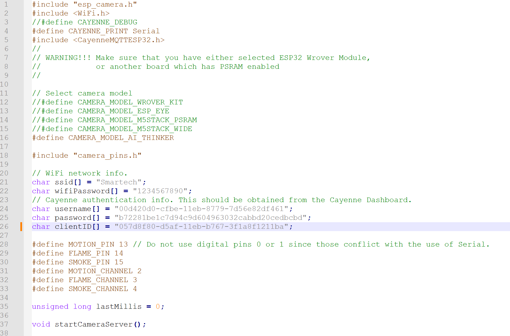
The source code used the ESP32 cam webserver library and the Cayenne library and you get to select the variant of ESP32 Cam that is being used by you. Also set the WiFi network details that you want the ESP32 cam to connect to for internet access. The Cayenne mydevices cloud details are also require in code line 24 through 26.
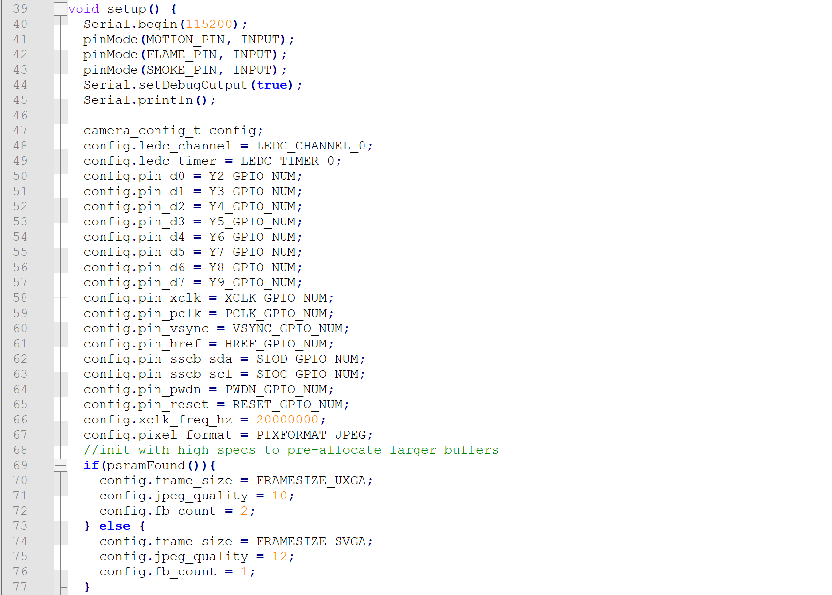
In the setup() function, we defined and declared which of our GPIO pins on the ESP32 Cam should serve as inputs or outputs. And since the motion sensor would also trigger the night-mode LED on the Bullet Camera casing to come on, we made the GPIO pin connected to this onboard LED to be an output.
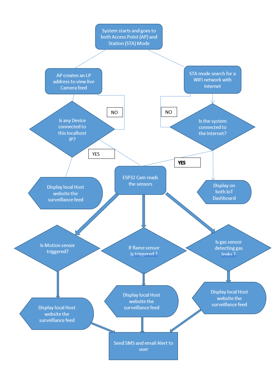
The rest of the code can be explained by this flowchart shown above.
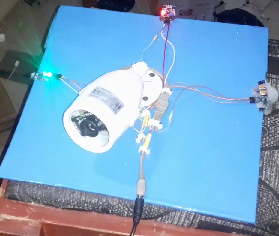
Casing the Fire Detection And Video Surveillance Project Design
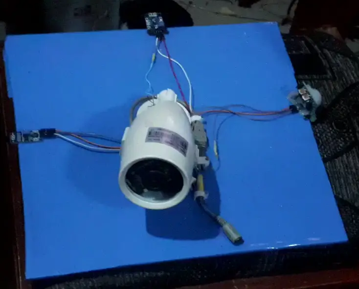
To make the ESP32 Cam board more presentable, we encased it in a bullet camera from an old and decommissioned CCTV set. This allowed us to protect it from dust and moist air.
Result and Testing
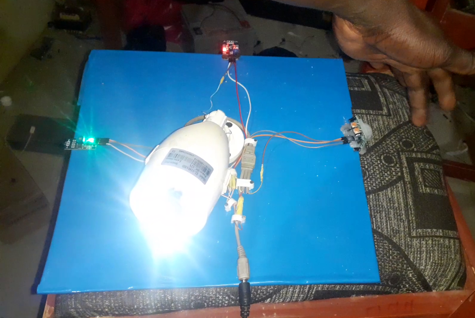
When powered on, the project comes alive, when it is dark and it detects motion, the LED comes on. Also it blinks when it is connected to a network with internet. all the sensors are powered on and are found to be working perfectly.
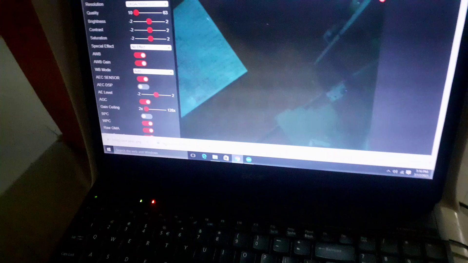
The video feed can be see running when one is connected to the LAN created by the project design. It will display or show anything where it is situated. and the IoT dashboard is also running effectively.
Conclusion
The Fire Detection And Video Surveillance Project design has been designed, fabricated and assembled. It can be used at home for remotely monitoring of fire incident and dangerous gas leakage like cooking gas that are both harmful to the body and could cause potential fire hazards. And the IoT dashboard makes it easy for anyone to receive alert of any parameter that may want to happen. Let us know if you have any questions in the comment section.

