This blog post, Generator Monitoring using Arduino and RemoteXY is about remote monitoring of generator over Wi-Fi system. The project design can measure the output AC voltage level of a generator, the temperature of the generator, to show it is overheating or not and also monitor and detect the feul level in the generator tank. All of these measured parameters will be displayed on the remote dashboard that can be accessed on an Android app of RemoteXY.
The project design is therefore divided into four units; the power supply unit (PSU), the Voltage Sensor Unit, the Temperature sensing unit and the fuel level detection unit. The power supply gives 5V DC to the project design. The voltage senor unit does the AC voltage measurements, whereas the temperature sensing unit senses the temperature of the generator and the feul level tells us the volume of the feul in the tank.
Components Needed For this Project Design
| Components | Quantity |
|---|---|
| DS18B20 sensor | 1 |
| Arduino Voltage sensor | 1 |
| 22K and 4.7K resistors | 1 each |
| Ultrasonic sensor HC-SR04 | 1 |
| 5V Zener Diode | 1 |
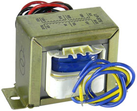
| 12V AC step-down transformer | 1 |
| bridge rectifier | 1 |
| 50uF 50V electrolytic capacitor | 1 |
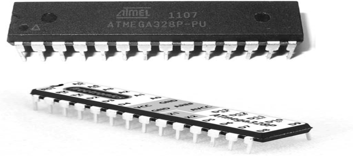
| Atmega328P IC | 1 |
| 100nF capacitor | 1 |
| LM7805 IC | 1 |
| Switch 1A | 1 |
| 22K Resistor | 1 |
| ESP8266-01 Module | 1 |
| 22pF capacitors | 2 |
| 16MHz Crystal | 1 |
| Female header pin | 2 sets |
| Male header pins | 2 sets |
| Connector and wires | 5 yards |
| Casing | 3×6 inch size |
Circuit Diagram for Generator Monitoring using Arduino and RemoteXY
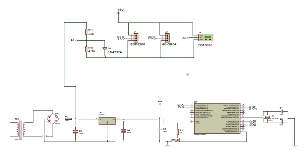
Explanation of the Circuit Diagram
The schematic diagram was designed using Proteus IDE, the schematic diagram begins with the connection of the step-down transformer to the AC mains. The step-down transformer give out 12V AC which is rectified by the bridge rectifier. There is a filter capacitor for AC ripples and a 5V regulator LM7805 IC, to produce 5V DC. This is further rectified by the 470uF and 100uF capacitors before connecting it to a pulldown resistor to the IO pin of the Atmega328P IC. This will work with the program that will tell us when the pushbutton is pressed.
The Atmega328P IC is powered by the 5V output from the power supply. Hence its connection to the power rails. The Atmega328P IC is also responsible for measuring the amplitude of AC voltage by using a voltage divider principle of the resistors connected in series. As well as use a serial communication protocol to communicate with the ESP-01 module.
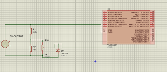
Also, the Voltage Sensor was taken from the power supply unit; by using the principle of Voltage Divider law (VDL). But also keeping at heart that the maximum current to any analogue pin of the microcontroller shouldn’t exceed 150mA (!≥ 150mA). To get 5V, having a 30.5KΩ known resistor in series with unknown resistor, the value of the unknown resistor was calculated as:

The Temperature Sensor Unit
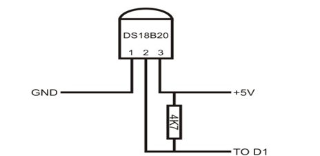
This IC which is also the brain of the project measure the temperature of the DS18B20 sensor.
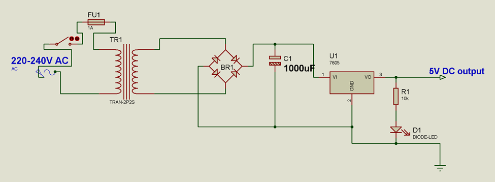
The power supply unit circuit is specifically designed as shown above. This circuit diagram is an excerpt of the complete design shown above. We brought this out just to show the stepdown process, the rectification process, the filtration process and the voltage regulation process. And a good design is further done when one can add an indictor that the power supply can output 5V by adding an LED indicator as shown in the circuit above.
Designing the RemoteXY App for Remote Monitoring
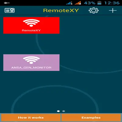
The designing of the RemoteXY app is pretty straight forward. Just go to the Remotexy website and log in after signing up. Read how to setup your dashboard on this HOW TO BUILD A WiFi BASED SMART FARM and read Smart Android System for more.
Programming Generator Monitoring using Arduino and RemoteXY Project
#include <DallasTemperature.h>

#include <OneWire.h>

//state where the input of the temp sensor is connected
#define ONE_WIRE_BUS A0

  int echoPin = 9;
  int trigPin = 10;
  long duration, cm, inches;

//set the OneWire lib to comm with other bus
OneWire oneWire(ONE_WIRE_BUS);
//transfer the data to Dallas temp Lib
DallasTemperature sensors(&oneWire);

// RemoteXY select connection mode and include library
#define REMOTEXY_MODE__ESP8266_HARDSERIAL_POINT

#include <RemoteXY.h>

// RemoteXY connection settings
#define REMOTEXY_SERIAL Serial
#define REMOTEXY_SERIAL_SPEED 115200
#define REMOTEXY_WIFI_SSID "ANSA_GEN_MONITOR"
#define REMOTEXY_WIFI_PASSWORD "9876543210"
#define REMOTEXY_SERVER_PORT 6377


// RemoteXY configurate
#pragma pack(push, 1)
uint8_t RemoteXY_CONF[] =
  { 255,0,0,248,1,63,0,8,61,0,
  129,0,1,8,97,9,16,65,78,83,
  65,95,71,69,78,95,77,79,78,73,
  84,79,82,0,67,0,2,36,97,7,
  16,26,101,67,0,37,36,62,7,16,
  26,101,67,0,67,36,32,7,16,26,
  101,67,0,1,29,97,9,16,26,201 };

// this structure defines all the variables of your control interface
struct {

    // output variable
  char VOLT[101];  // string UTF8 end zero
  char FUEL[101];  // string UTF8 end zero
  char TEMP[101];  // string UTF8 end zero
  char TEXT[201];  // string UTF8 end zero

    // other variable
  uint8_t connect_flag;  // =1 if wire connected, else =0

} RemoteXY;
#pragma pack(pop)

/////////////////////////////////////////////
//           END RemoteXY include          //
/////////////////////////////////////////////


//declear the voltage initial state
float Vout = 0.0;
float  Vin = 0.0;
//declear the resistors used in VDL of Voltage sensor
float R1 = 9820.0;
float R2 = 2150.0;

void setup()
{
  RemoteXY_Init ();

 //begin the temp sensor
  sensors.begin();

  //outline the inputs and output pins

  pinMode(trigPin, OUTPUT);
  pinMode(echoPin, INPUT);

}

void loop()
{
  RemoteXY_Handler ();
  sprintf (RemoteXY.TEXT, "GEN_VOLTAGE (V):            FUEL (Litres):              GEN_TEMP ('C):");
  double sense = analogRead(A1);
  double Vout = (sense * 5.0)/1023.0;
  double Vin = Vout /(R2/(R1+R2));
  double voltage = (Vin + 1.1) * 16.0;
  int AC = voltage;
 dtostrf(voltage, 0, 2, RemoteXY.VOLT);

   //trigger the U sensor
  digitalWrite(trigPin, LOW);
  delay(5);
  digitalWrite(trigPin, HIGH);
  delay(10);
  digitalWrite(trigPin, LOW);
  //ask the U sensor to start measuring dist
  duration= pulseIn(echoPin, HIGH);
  //get the dist in cm by dividing 148 ie how
  //how long it takes the U sender to send
  //and received by its receiver
  cm = duration/58;
  double r = 9.00;
  double rubber = 3.142* ((r) * (r) * cm);
  double litre = rubber/1000.00;
  dtostrf(litre, 0, 2, RemoteXY.FUEL);


  sensors.requestTemperatures();
  float Temp = sensors.getTempCByIndex(0);
  dtostrf(Temp, 0, 2, RemoteXY.TEMP);

  delay(500);
}
Testing and Results
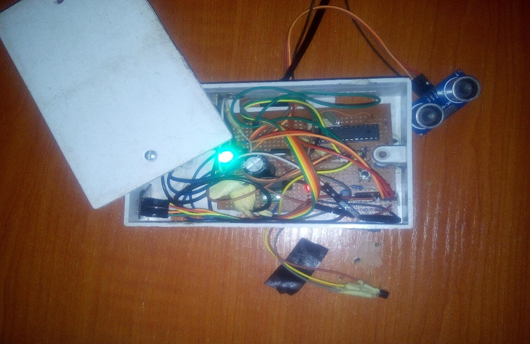
The Generator Remote Monitoring System is shown above. It has been encased and in the 3×6 inch pattress box. And The Ultrasonic sensor is brought outside as well as the temperature sensor. These are to be afixed at specific spots on the generator body. Namely, on top of the generator feul tank and the body of the generator. However we tested it at a feul level when the tank is almost empty.
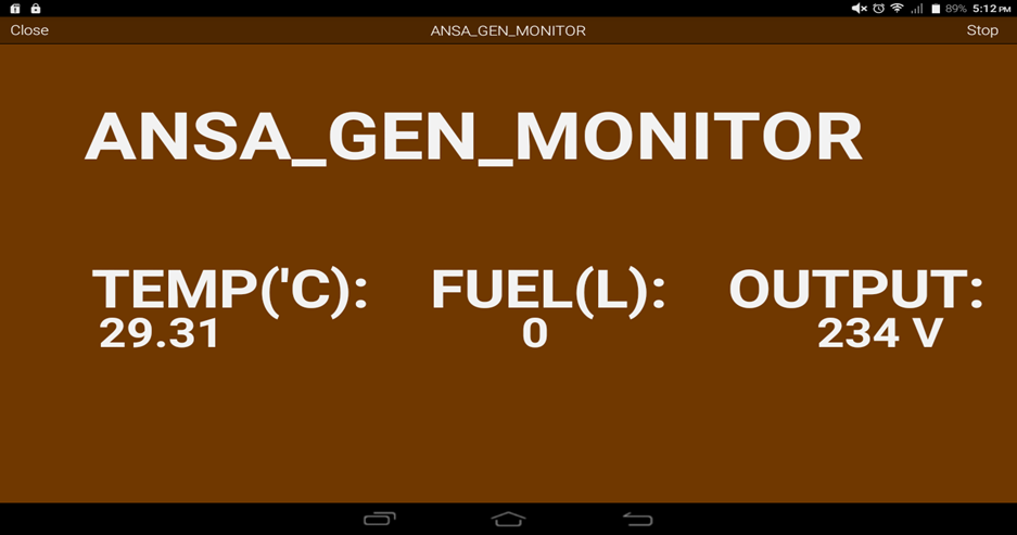
When the design is powered on, after ensuring the phone device is connected to the WiFi network created by the device. We opened the RemoteXY app and checked the device monitor. The result was shown above. We had a voltage level of 234V and a temperature of 29.31 degree Celsius. The feul level was 0 and this was expected since the tank was almost drained.
Conclusion
The Generator Remote Monitoring System project design has been designed and tested to be working as programmed. We will like to know if you performed the same process by following the steps mentioned in this blog post. Let us know in the comments below.

