This IoT based project uses an NPK sensor to measure the soil nutrient available in the soil and then displays it in an OLED as well as sending the read soil values to Blynk IoT dashboard as shown above. The project is very important to agriculture and gardening practices.
IoT NPK Fertility Analyzer – The Components Required
The following are the materials used for this IoT NPK project tutorial.
- Soil NPK Sensor
- Arduino Nano
- ESP8266-01 (ESP-1)
- 12V Power Supply Module
- OLED
- Max485 Module
- Jumper Wires
- Button Switch
- DC-DC Buck converter
- A pushbutton
- Some PCB socket
- Male and Female Socket Wires
- LED (green and red LED)
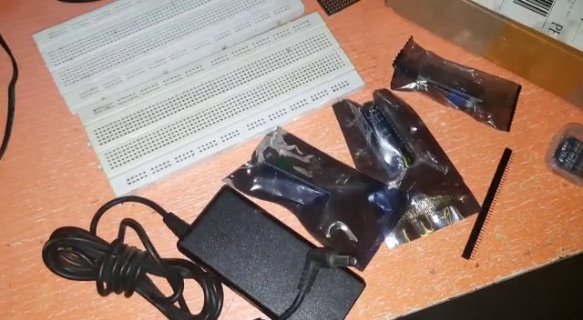
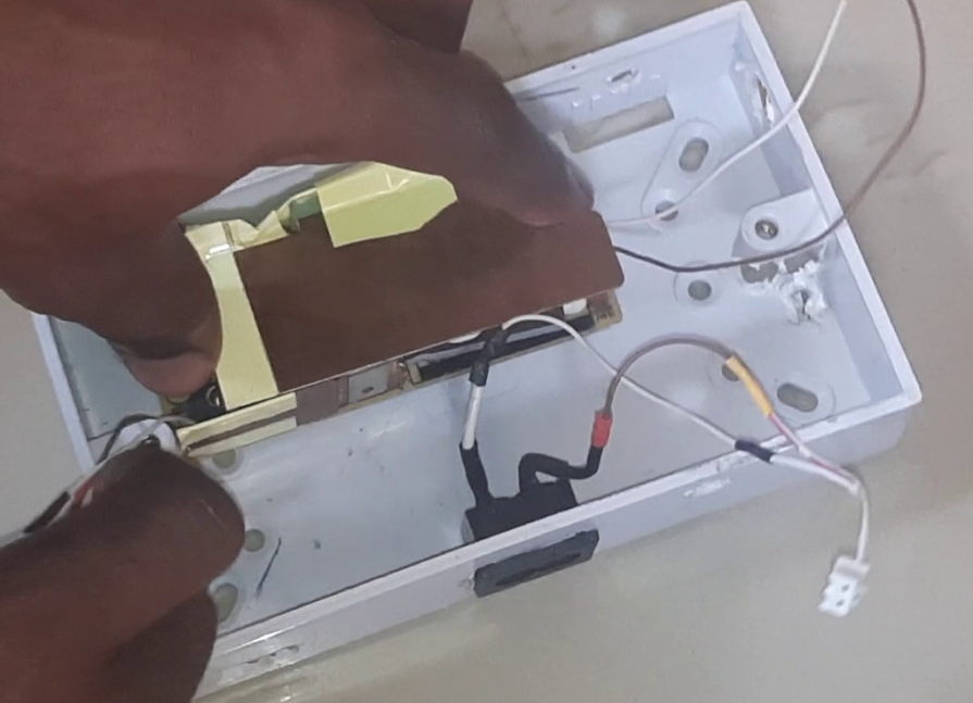
The IoT based NPK fertilizer analyzer project was first assembled using the breadboard, as shown above. The breadboarding phase allowed for the testing of of the project tutorial, giving room for error making and modification. The setting up and connection of the components on the breadboard is done following the schematic diagram shown below.
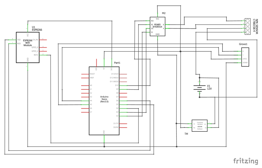
IoT Based NPK Sensor Project – Schematic Diagram
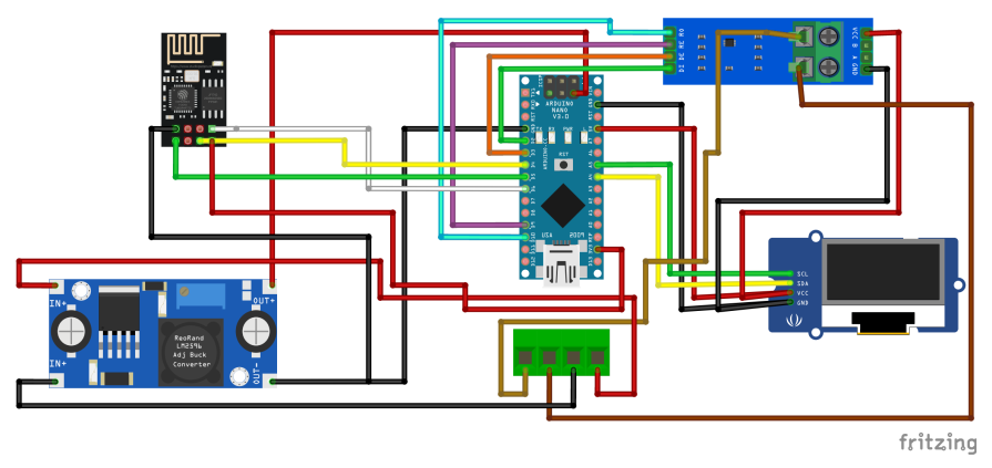
Explanation of the Schematic Diagram
The pictorial schematic diagram shown above, has exclusion of the power connection. We only focused the connection of the 5V coming out from the DC-DC buck converter. The 12V power supply is fed into the PCB socket (shown in green).
The ESP8266-01 (ESP-01) module is connected to the Arduino Nano board using serial communication since the Blynk IoT platform to be used here doesn’t work well with the I2C communication. Hence, the OLED doesn’t work with the libraries of Blynk when using the both of them on the same Arduino board.
To solve this problem, we used the ESP-01 as a microcontroller instead of a module, then we used serial communication protocol to talk to it through the Arduino Nano. The Arduino Nano would do the job of taking the readings of the soil fertility through the NPK sensor, displaying these sensor readings on the OLED module and sending it through serial to the ESP-01, who would in turn send it to the Blynk dashboard.
The MAX485 module helps us maintain a RS485 to TTL communication between the NPK sensor and the Arduino. The MAX485 module uses the 5V logic from the Arduino to power itself and it is connected as shown below.

Powering the Circuitry
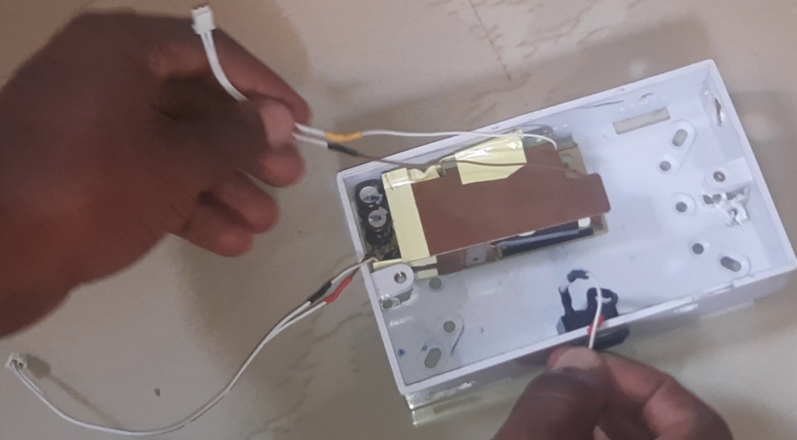
The system itself uses 12V DC power from a 12V adapter. The adapter is first stripped of its casing and made in such a way that it can fit into a 3×6″ box. The adapter 12V DC output is connected to the 12V input of the NPK power rails and also to the input of the DC-DC buck converter. This is bucked down to 5V for the Arduino Nano board and the MAX485 module. The AC input to the adapter is connected to the AC load point through power plug. This was made in such a way that is can be detachable.
Programing the IoT NPK Project Design
The programming of this project was using Arduino IDE. The source code is found in the link here. You can also copy the one in the code snippet and paste it into your Arduino IDE and run it. Since the Arduino Nano does the sensor reading and calculation and displays these readings on the OLED the same time it sends the said readings to the ESP-01 snesor who would send it to the IoT Blynk platform.
Arduino Source Code – The Transmitter Side
#include <SoftwareSerial.h>
#include <SPI.h>
#include <Wire.h>
#include <Adafruit_GFX.h>
#include <Adafruit_SSD1306.h>

#define SCREEN_WIDTH 128 // OLED display width, in pixels
#define SCREEN_HEIGHT 64 // OLED display height, in pixels

// Declaration for an SSD1306 display connected to I2C (SDA, SCL pins)
#define OLED_RESET     4 // Reset pin # (or -1 if sharing Arduino reset pin)
Adafruit_SSD1306 display(SCREEN_WIDTH, SCREEN_HEIGHT, &Wire, OLED_RESET);
define RE 8
#define DE 7

//const byte code[]= {0x01, 0x03, 0x00, 0x1e, 0x00, 0x03, 0x65, 0xCD};
const byte nitro[] = {0x01,0x03, 0x00, 0x1e, 0x00, 0x01, 0xe4, 0x0c};
const byte phos[] = {0x01,0x03, 0x00, 0x1f, 0x00, 0x01, 0xb5, 0xcc};
const byte pota[] = {0x01,0x03, 0x00, 0x20, 0x00, 0x01, 0x85, 0xc0};

#define buttonPush 7
#define sensorReadPin 8

int readButton, readSensor;
int count = 0;
int countDown = 5;
int a, i = 0;

int n, p, k;
String greeting = "hello";

byte values[11];
SoftwareSerial mod(2,3);
void setup() {
  Serial.begin(9600);
  mod.begin(9600);
  pinMode(RE, OUTPUT);
  pinMode(DE, OUTPUT);

  display.begin(SSD1306_SWITCHCAPVCC, 0x3C); //initialize with the I2C addr 0x3C (128x64)
  delay(500);
  display.clearDisplay();
  display.setCursor(25, 15);
  display.setTextSize(1);
  display.setTextColor(WHITE);
  display.println(" WELCOME SMART");
  display.setCursor(15, 35);
  display.setTextSize(1);
  display.print("SOIL NPK DETECTION");
  display.setCursor(45, 55);
  display.setTextSize(1);
  display.print("PROJECT");
  display.display();
  delay(3000);
}

void loop() {
 byte val1,val2,val3;
 val1 = nitrogen();
 delay(250);
 val2 = phosphorous();
 delay(250);
 val3 = potassium();
 delay(250);


 Serial.print("Nitrogen: ");
 Serial.print(val1);
 Serial.println(" mg/kg");
 Serial.print("Phosphorous: ");
 Serial.print(val2);
 Serial.println(" mg/kg");
 Serial.print("Potassium: ");
 Serial.print(val3);
 Serial.println(" mg/kg");
 delay(2000);

 display.clearDisplay();


 display.setTextSize(2);
 display.setCursor(0, 5);
 display.print("N: ");
 display.print(val1);
 display.setTextSize(1);
 display.print(" mg/kg");

 display.setTextSize(2);
 display.setCursor(0, 25);
 display.print("P: ");
 display.print(val2);
 display.setTextSize(1);
 display.print(" mg/kg");

 display.setTextSize(2);
 display.setCursor(0, 45);
 display.print("K: ");
 display.print(val3);
 display.setTextSize(1);
 display.print(" mg/kg");

 display.display();
Explanation of Arduino Sketch
The transmitter Arduino sketch allows us to use the serial communication protocol to communicate with the MAX485 module to read the NPK sensor. This shows where the Transmitter and receiver pins of the MAX485 module is connected on the Arduino Nano board. The sketch uses 5 libraries to make the whole setup function perfectly for the Arduino Nano side.
In the setup() function, we enabled the OLED function and displayed a welcome message and after a period of 3 seconds we cleared the screen. The program then checks to see of the NPK sensor is connected. And if it was connected, it will display that it was connected hence proceed to take the sensor readings of the soil levels for Nitrogen, Phosphorus and Potassium. This is printed out on the serial monitor and also sent to the ESP-01 MCU since the Arduino Nano baords communicate to the ESP-01 via hardware serial communication and this is enabled the moment we enabled serial communication in the setup().
However, The method of sending this type of data required a special approach so that it can be parsed easily by the receiving end. We had to use special alphabets to concatenate the strings being sent to the serial buffer.
The Arduino Code – The Receiver Side (ESP-01 MCU)
#include <SoftwareSerial.h>

SoftwareSerial esp(4,5);

const byte numChars = 32;
char receivedChars[numChars];
char tempChars[numChars];        // temporary array for use when parsing
boolean newData = false;

// variables to hold the parsed data
char messageFromPC[numChars] = {0};
int n, p, k = 0;

static boolean recvInProgress = false;
static byte ndx = 0;
char startMarker = '<';
char endMarker = '>';
char rc;

void recvData(){

 }


void setup(){
  // Debug console
  Serial.begin(115200);
  esp.begin(115200);

  }

void loop(){
recvWithStartEndMarkers();
    if (newData == true) {
     strcpy(tempChars, receivedChars);
     // this temporary copy is necessary to protect the original data
      //   because strtok() used in parseData() replaces the commas with \0
     parseData();
     showParsedData();
     newData = false;
    }

}

void recvWithStartEndMarkers() {
    while (esp.available() > 0 && newData == false) {
        rc = esp.read();

        if (recvInProgress == true) {
            if (rc != endMarker) {
                receivedChars[ndx] = rc;
                ndx++;
                if (ndx >= numChars) {
                    ndx = numChars - 1;
                }
            }
            else {
                receivedChars[ndx] = '\0'; // terminate the string
                recvInProgress = false;
                ndx = 0;
                newData = true;
            }
        }

        else if (rc == startMarker) {
            recvInProgress = true;
        }
    }
}

//============

void parseData() {      // split the data into its parts

    char * strtokIndx; // this is used by strtok() as an index

    strtokIndx = strtok(tempChars,",");      // get the first part - the string
    strcpy(messageFromPC, strtokIndx); // copy it to messageFromPC

    strtokIndx = strtok(NULL, ","); // this continues where the previous call left off
    n = atoi(strtokIndx);

    strtokIndx = strtok(NULL, ",");
    p = atoi(strtokIndx);     // convert this part to a float

    strtokIndx = strtok(NULL, ","); // this continues where the previous call left off
    k = atoi(strtokIndx);     // convert this part to an integer
    Serial.print(" N: ");
    Serial.print(n);
    Serial.print(" P: ");
    Serial.print(p);
    Serial.print(" K: ");
    Serial.println(k);
}

//============

void showParsedData() {
    Serial.print(" N: ");
    Serial.print(n);
    Serial.print(" P: ");
    Serial.print(p);
    Serial.print(" K: ");
    Serial.println(k);

}
Explanation of Arduino Sketch (Receiver Side)
This source code explains how we used software serial comm. to received the sent data strings from the Arduino Nano. We used the logic above to parse the data sent and then sent this data to the Blynk IoT Dashboard. This is a smart and cost effective way to solve the Blynk and OLED libraries issues. Since, the both of them can’t run together on the same ARDUINO UNO AND NANO BOARDS.
Setting up the Blynk IoT Platform
You can check out any of these previous blog links below on how to set up the Blynk dashboard. If you still can’t get it done. Kindly leave a comment below.
- IOT REMOTE MONITORING OF THE VOLTAGE USING BLYNK
- IoT Light Bulb – Remote Control Light Bulb Blynk App
- Electrical Socket to Smart Plug Socket with ESP32 CAM Arduino Blynk app
Testing the Design
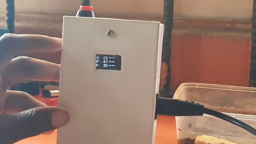
When the coupling and tidying up was completed, we used a white wrapper to cover the top enclosure making a bit flashy. The OLED screen is made to show on the top cover. There is a pushbutton on the side to reset the microcontroller to take new readings on insertion of the sensor probe into a new soil sample. And the sensor connection is made detachable to make it plug-N-play.
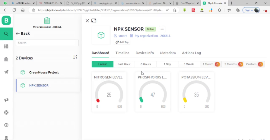
The ESP-01 MCU would take these readings to the Blynk cloud platform and display them on the dashboard as shown above. The readings will be updated the moment the sensor senses new soil parameters.
Kindly note that the NPK sensor can be quite frustrating to use. Kindly get an original copy for this project to work. IF possible, get the type that has a UART USB reader that can be first tested using a PC program before using it with the MAX485 module.
Conclusion
The project tutorial teaches how to use Soil NPK sensor to monitor the soil fertility concentrations. Soil parameters like the Nitrogen, Phosphate and Potassium concentration level can be remotely monitored on an IoT Blynk platform.

