This project concentrated on selecting an approach that would design an IoT based green house project. The task at hand was to devise and build a greenhouse irrigation model with the ability to inspect, control, and monitor the temperature and humidity of the plant. While regulating the soil level, it will also keep an eye on the moisture level of the soil. The concept was intended to be based on the internet of things (IoT). This implied that it could be managed and observed remotely from anywhere in the world.
The Materials Required for this Project
The table below is the materials required for this project construction. Also we have included the the quantity needed. You can head over to our online shop to get most of the items here.
| ITEM DESCRIPTION | QUANTITY | UNIT COST | TOTAL UNIT |
| LiPo CHARGING MODULE | 1 | ||
| DHT22 | 1 | ||
| 3×6 INCH PATRESS BOX | 1 | ||
| Connector | 3 | ||
| RESISTORS | 2 | ||
| CONNECTING WIRES | 3 yards | ||
| Sil Moisture sensor | 1 | ||
| MQ135 SENSOR | 1 | ||
| LIPO BATTERY | 1 | ||
| SOLDER | 1 | ||
| SOLDERING IRON | 1 | ||
| Buzzer | 1 | ||
| NodeMCU Board | 1 | ||
| Acryllic glass | 1 | ||
| Plastic container | 1 | ||
| Plywood board | 1 | ||
| Glue stick | 10 | ||
| DC SWITCH | 1 | ||
| FEMALE HEADERPIN | 2 | ||
| MISCELLANEOUS |
Schematic Diagram for the IoT Based Green House Project
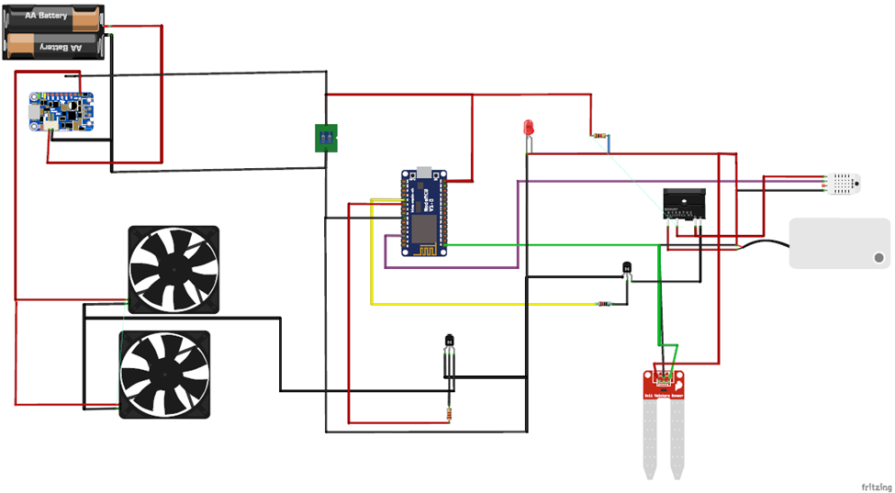
The DC fans are connected in parallel to each other and are energized by an NPN transistor which is fired at the base by an 1k resistor. When the button on the web dashboard is pressed, the received signal indicates the state of the DC fan. Either to baise the base of the transistor or not. The DC pump is also controlled by the transistor since it demands some initial current at start up. The base of the resistor is connected to a 1k resistor that is connected to a GPIO pinon the NodeMCU. When this GPIO pin is high at 3.3V, the base of the transistor is biased, and when it is LOW it is not biased.

The soil moisture level sensor is connected to the only ACD pin on the NodeMCU, this is the A0 pin. The analog output pin (A0) was connected to this A0 on the NodeMCU. And a program was used to read the analog reading of the sensor. Alternatively, you can download the code and schematic diagram from the link here.
Programming the Project (Arduino Sketch)
 #define BLYNK_TEMPLATE_ID "xxxxxxxxxxxxxxxx" //replace with your unique ID
#define BLYNK_TEMPLATE_NAME "Green House Project"
#define BLYNK_AUTH_TOKEN "xxxxxxxxxxxxxxxxxxxx" //replace with your token

#include "DHT.h"

// Comment this out to disable prints and save space
#define BLYNK_PRINT Serial

#include <ESP8266WiFi.h>
#include <BlynkSimpleEsp8266.h>

char auth[] = BLYNK_AUTH_TOKEN;

char ssid[] = "Galaxy A51 917E";
char pass[] = "ancsucre21";

#define DHTPIN D3     // Digital pin connected to the DHT sensor
//outline the actuATORS
#define dcFan D6
#define dcPump D8
#define humdifier D5
//state the inputs
#define soilMostureSensor A0
// Uncomment whatever type you're using!
//#define DHTTYPE DHT11   // DHT 11
#define DHTTYPE DHT22   // DHT 22  (AM2302), AM2321
//#define DHTTYPE DHT21   // DHT 21 (AM2301)

DHT dht(DHTPIN, DHTTYPE);
//variables
float h, t, f;

int readSoil, pumpButton, tempButton, humidifierButton;

BLYNK_WRITE(V3) {
 pumpButton = param.asInt();
if((readSoil > 19) && (readSoil <= 54)){
  if (pumpButton==1){
  digitalWrite(dcPump, HIGH);
    }
  else if(pumpButton==0){
    digitalWrite(dcPump, LOW);
    }
  }
}

BLYNK_WRITE(V4) {
 tempButton = param.asInt();
 Serial.println(tempButton);
if((t > 19) && (t <= 40)){
    if (tempButton==1){
digitalWrite(dcFan, HIGH);
    }
else if(tempButton==0){
  digitalWrite(dcFan, LOW);
    }
  }
}

BLYNK_WRITE(V5) {
  humidifierButton = param.asInt();
    if (humidifierButton==1){
      pressHum();
    }
else if(tempButton==0){
  Serial.println("press again");
    }
}

void pressHum(){
  digitalWrite(humdifier, LOW);
 delay(100);
 digitalWrite(humdifier, HIGH);
}

void setup() {
  //begin serial comm.
  Serial.begin(9600);
    //state the actuators as outputs
  pinMode(dcPump, OUTPUT);
  pinMode(humdifier, OUTPUT);
  pinMode(dcFan, OUTPUT);

  //turn off humidifier
 pressHum();
 delay(3000);
 pressHum();
 delay(3000);
pressHum();
  //begin the dht sensor
   dht.begin();
  Blynk.begin(auth, ssid, pass);

 digitalWrite(dcFan, LOW);

}

void turnOffHumidifier(){
pressHum();
delay(3000);
pressHum();
delay(3000);
pressHum();
   }

void turnOnHumidifier1(){
pressHum();
   }

void turnOnHumidifier2(){
pressHum();
delay(3000);
pressHum();

}

//create a fxn to read the temp and hum
float readTempHum(){
  // Reading temperature or humidity takes about 250 milliseconds!
  // Sensor readings may also be up to 2 seconds 'old' (its a very slow sensor)
  h = dht.readHumidity();
  // Read temperature as Celsius (the default)
   t = dht.readTemperature();
  // Read temperature as Fahrenheit (isFahrenheit = true)
   f = dht.readTemperature(true);

  // Check if any reads failed and exit early (to try again).
  if (isnan(h) || isnan(t) || isnan(f)) {
    Serial.println(F("Failed to read from DHT sensor!"));
    //return;
  }
  // Compute heat index in Fahrenheit (the default)
  float hif = dht.computeHeatIndex(f, h);
  // Compute heat index in Celsius (isFahreheit = false)
  float hic = dht.computeHeatIndex(t, h, false);

  return t, h;
}

void conditionalStatements(){
  readTempHum();
  soilMoisture();

  if(t >= 40.00){
    digitalWrite(dcFan, HIGH);
 }

 if (t <= 15.00) {
 digitalWrite(dcFan, LOW);
 }

// if(h <= 15.00){
//   turnOnHumidifier1();
//    }
//
//  if(h > 50.00)  {
//    turnOffHumidifier();
//  }

   if(readSoil < 18){
    digitalWrite(dcPump, HIGH);
  }

  if(readSoil >= 55){
    digitalWrite(dcPump, LOW);
  }
//  Serial.println(readSoil);
//  delay(500);
}

int soilMoisture(){
  readSoil = analogRead(soilMostureSensor);
  readSoil = map(readSoil, 0, 1023, 100, 0);
  readSoil = constrain(readSoil, 0, 100);

  return readSoil;
}


void loop() {
  conditionalStatements();
  Blynk.run();
  Blynk.virtualWrite(V0, t);
  Blynk.virtualWrite(V1, h);
  Blynk.virtualWrite(V2, readSoil);
}
Read More
- GPS and SMS Based Fall Detection and Prevention Project
- How to Design a Smart Automatic Trash Basket
- Temperature Control Fan Arduino Proteus Simulation
Web App Control and Result
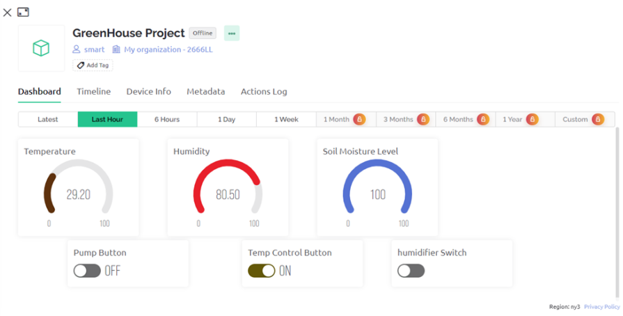
This is displayed widgets on the web app. It has three (3) controls namely, the pump button which is a widget that controls the state of the DC pump of the greenhouse model, the temperature control button, which is responsible for turning on the DC fans; and the humidifier button, which controls the humidifier device in the greenhouse model farm. The Blynk web app has three (3) display widgets to monitor and track the state of the temperature, the humidity, and the soil moisture level. This is shown in the image above. The control widgets use a separate function code to send signals to the NodeMCU when they are switched or they change state while the display widgets use a different function in the program code to write to the Blynk cloud to only display.
Thinning, Soldering and Casing the IoT Based Greenhouse Project
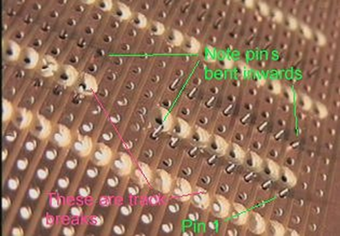
Thinning involves the smooth scrapping of terminal components, either by knife or sand paper, before soldering.
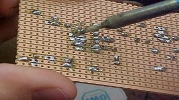
Soldering involves the joining of the conductors or components terminals to the circuit board by means of soldering iron and soldering wire. This process was carried out after the terminals of the component have been thinned and positive results have been obtained from the testing of the component.
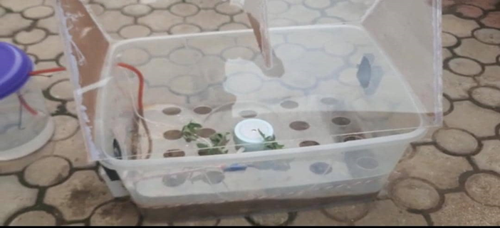
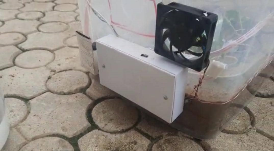
The casing was made to be a house for some of the components. The casing encased the most of the components and modules use in the project design. It was made from a (3×6) inch pattress box.
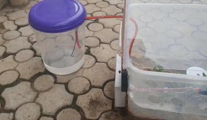
The greenhouse model was made using a transparent encasing as shown above. It measured 50cm x 60cm x 40cm in dimension. The model roof was an acrylic glass that was also transparent. The inside of the box was modelled to perform underground irrigation by placing hose running beneath a soil layer. Two openings were cut for the fan inflow of air and outflow of air. This was to control the temperature through natural means. When the greenhouse model was hot or above optimum temperature, cool air was supplied inside.
The Result
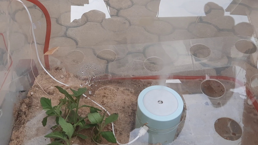
The IoT based greenhouse project was made to control the humidity of the plants inside the model greenhouse by increasing the level of moisture around the plants through the spraying of moist air using a humidifier. This is remotely controlled also through the Blynk IoT app. And also controlled automatically by the brain of the project which is the microcontroller. As shown in the image above, the level of water in the soil will determine if the pump should turn on automatically or remain turned off. The user can also control these parameters by online dashboard.
Conclusion
The IoT-based Green House Project has been designed and tested to work. Let us know in the comment section if you were able to replicate this project or if you made some modifications of your own to it.

