In this post today, we will be doing a temperature control fan simulation using Arduino and Proteus Design and Circuit IDE. This post is a continuation of of our previous Home Automation Simulation. In the previous post, we were able to turn on and off the light bulb using the PIR motion sensor. In this very post, we will be adding a digital and humidity sensor (DHT11) to sensor the virtual temperature of the room and hence regulate the temperature by ensuring that when the temperature goes too hot, the fan increases its speed to the maximum and when the temperature is too cold, the fan’s speed decreases until it finally turns off.
Temperature Fan Control Simulation
To proceed further on this, we are assuming that you have the knowledge of how to install the Proteus version used in this tutorial by reading the previous post and also how to create a new project on Proteus Design and Circuit IDE. It is pretty much easy, just follow the previous blog post.
The Components Needed
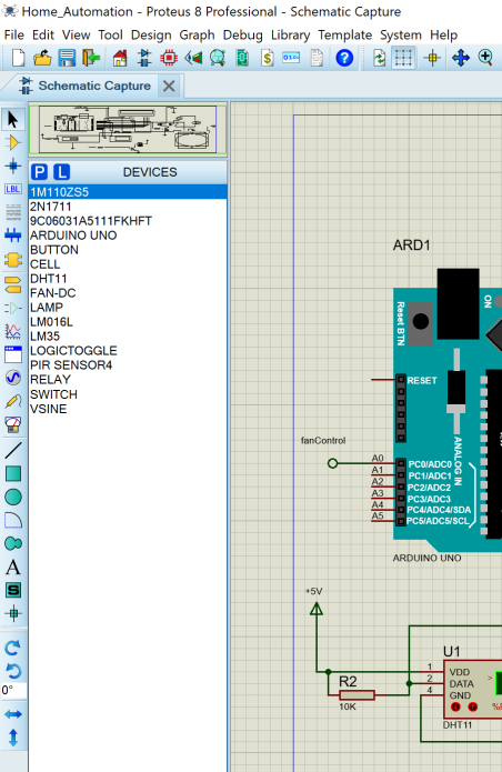
The Proteus components needed for this tutorial is listed in the image above. You can just type the exact part number or model names as show there. However in summary we used the Zener diode 1M110Z5S as flywheel for the relay module created with the NPN transistor. The Arduino Uno is the heart and brain of the simulation. We used a push-button and a switch to to give the user control over the fan and the simulated room light bulb. This means that if the user wanted the fan to be turned on and regulated by the internal temperature sensor (DHT11), he/she could just press the switch. But the light bulb is triggered by the motion sensor automatically. However if the user wanted the light bulb to remain turned off, he/she could just push the push-button.
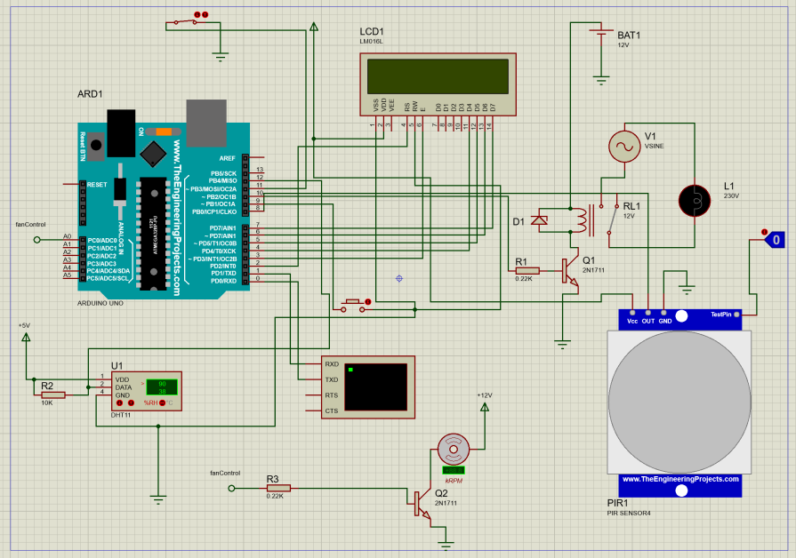
The connection to the whole components is shown in the above diagram, we just need to add a few components to our last tutorial. We needed the DHT11 sensor and this can be gotten from the search menu after we click on pick component icon. The DC fan too and the extra NPN transistor that was connected to it. We used a 12V power supply to power it.
Programming the Proteus Simulation
The Arduino Sketch
The Arduino sketch to this design is found in the simulation folder on Github. You can download the file and unzip, and open it in your Arduino IDE. Alternatively, you can also just copy the code off here.
// include the library code:
#include <LiquidCrystal.h>
#include "DHT.h"

//show where the actuator and sensors are connected
#define pirPin 8
#define pushButtonPin 9
#define relayPin 10
int fanSwitch = 11;
int fanControl = A0;
//show where the dht11 sensor was connected
#define DHTPIN 12

#define DHTTYPE DHT11  // we are using DHT11

DHT dht(DHTPIN, DHTTYPE);

// Variables will change:
int ledState = HIGH;        // the current state of the output pin
int buttonState;            // the current reading from the input pin
int lastButtonState = LOW;  // the previous reading from the input pin

unsigned long lastDebounceTime = 0;  // the last time the output pin was toggled
unsigned long debounceDelay = 10;    // the debounce time; increase if the output flickers

// state where the arduino pin number it is connected to on LCD
const int rs = 2, en = 3, d4 = 4, d5 = 5, d6 = 6, d7 = 7;
LiquidCrystal lcd(rs, en, d4, d5, d6, d7);

void setup() {
  // set up the LCD's number of columns and rows:
  lcd.begin(16, 2);
  //begin the serial monitor comm.
  Serial.begin(9600);
  //beging the dht11 sensor
  dht.begin();
  //state the fxn for the inputs and outputs
  pinMode(pirPin, INPUT);
  pinMode(pushButtonPin, INPUT_PULLUP);
  pinMode(relayPin, OUTPUT);
  pinMode(fanSwitch, INPUT_PULLUP);
  pinMode(fanControl, OUTPUT);
  // Print a welcome message to the LCD.
  lcd.setCursor(0, 0);
  lcd.print("HELLO THERE?");
  delay(100);
  lcd.clear();
  lcd.setCursor(0, 0);
  lcd.print("MOTION BASED");
  lcd.setCursor(0, 0);
  lcd.print("HOME AUTOMATION");
  delay(100);
  lcd.clear();
  lcd.setCursor(0, 0);
  lcd.print("SIMULATION");
  delay(100);
  lcd.clear();
  //read the pir sensor
  while (digitalRead(pirPin) == 0) {
    lcd.clear();
    lcd.setCursor(0, 0);
    lcd.print("   NO MOTION");
    lcd.setCursor(0, 1);
    lcd.print("DETECTED IN ROOM");
    Serial.println("NO MOTION DETECTED");
    delay(50);
    turnOffBulb();
    delay(100);
  }
  if (digitalRead(pirPin) == 1) {
    lcd.clear();
    lcd.setCursor(0, 0);
    lcd.print("MOTION DETECTED");
    Serial.println("MOTION DETECTED");
    delay(50);
    turnOnBulb();
    delay(100);
  }
}

void turnOnBulb() {
  digitalWrite(relayPin, HIGH);
  Serial.println("LIGHT BULB TURNED ON");
  lcd.clear();
  lcd.setCursor(0, 0);
  lcd.print("LIGHT BULB");
  lcd.setCursor(0, 1);
  lcd.print("TURNED ON");
}

void turnOffBulb() {
  digitalWrite(relayPin, LOW);
  Serial.println("LIGHT BULB TURNED OFF");
  lcd.clear();
  lcd.setCursor(0, 0);
  lcd.print("LIGHT BULB");
  lcd.setCursor(0, 1);
  lcd.print("TURNED OFF");
}

void controlFan() {

  float h = dht.readHumidity();
  // Read temperature as Celsius (the default)
  float t = dht.readTemperature();
  // Read temperature as Fahrenheit (isFahrenheit = true)
  float f = dht.readTemperature(true);

  //print out the readings
  Serial.print(F("Humidity: "));
  Serial.print(h);
  Serial.print(F("%  Temperature: "));
  Serial.print(t);
  Serial.print(F("°C "));
  Serial.println(digitalRead(fanSwitch));

  lcd.clear();
  lcd.setCursor(0, 0);
  lcd.print("T: " +String(t, 1)+ "'C H: " + String(h,0) + "%");

  if (digitalRead(fanSwitch)== 1) {
    if (t > 37.00) {
      for (int i = 50; i < 256; i++) {
        analogWrite(fanControl, i);
        lcd.setCursor(0, 1);
        lcd.print("FAN ON");
      }
    }
      if (t < 35.00) {
        analogWrite(fanControl, LOW);
        lcd.setCursor(0, 1);
        lcd.print("FAN OFF");
      }
  }

  if (digitalRead(fanSwitch) == 0) {
    analogWrite(fanControl, LOW);
    lcd.setCursor(0, 1);
    lcd.print("FAN OFF");
  }
}

void loop() {
  //read the pir sensor
  bool readPir = digitalRead(pirPin);
  // read the state of the switch into a local variable:
  int reading = digitalRead(pushButtonPin);
  controlFan();
  delay(100);
  // If the switch changed, due to noise or pressing:
  if (reading != lastButtonState) {
    // reset the debouncing timer
    lastDebounceTime = millis();
  }

  if ((millis() - lastDebounceTime) > debounceDelay) {
    // if the button state has changed:
    if (reading != buttonState) {
      buttonState = reading;

      // only toggle the LED if the new button state is HIGH
      if (buttonState == HIGH) {
        ledState = !ledState;
      }
    }
  }

  //use an if condition to check for the motion
  if (ledState == 0) {
    if (readPir == 1) {
      lcd.clear();
      lcd.setCursor(0, 0);
      lcd.print("MOTION DETECTED");
      Serial.println("MOTION DETECTED pushbutton: " + String(reading) + " LED state: " + String(ledState));
      delay(50);
      turnOnBulb();
      delay(100);
    }
  }

  if (ledState == 1) {
    if (readPir == 1) {
      lcd.clear();
      lcd.setCursor(0, 0);
      lcd.print("MOTION DETECTED");
      lcd.setCursor(0, 1);
      lcd.print("USER OFF LIGHT");
      Serial.println("MOTION DETECTED pushbutton: " + String(reading) + " LED state: " + String(ledState));
      delay(50);
      turnOffBulb();
      delay(100);
    }

    if (readPir == 0) {
      lcd.clear();
      lcd.setCursor(0, 0);
      lcd.print("NO MOTION DETTED");
      lcd.setCursor(0, 1);
      lcd.print("USER OFF LIGHT");
      Serial.println("NO MOTION DETECTED pushbutton: " + String(reading) + " LED state: " + String(ledState));
      delay(50);
      turnOffBulb();
      delay(100);
    }
  }
  // save the reading. Next time through the loop, it'll be the lastButtonState:
  lastButtonState = reading;
  delay(100);
}
Explanation of The Arduino Code
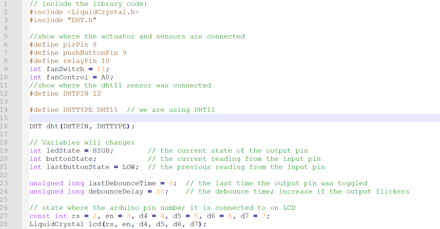
We began by including the LCD library. This is needed to show the user what is going on in the simulated virtual room. We also included the library for the temperature sensor, DHT11 in code line 3. We declared and defined where we connected the PIR sensor digital output pin (which is digital pin 8). The relay transistor base is connected to digital pin 10 on the Uno board, the Fan Auto Mode switch is connected to D11, while the DHT11 digital output pin is connected to D12 on the virtual Arduino Uno board. This as shown from code line 6 through 12.
We used dome variables to hold the states of the AC light bulb so as to allow the user change the turning on and off of the bulb. These variables in code line 19 and 21 helps us to enable the user to turn off the light bulb when the motion sensor triggers it on and it stays off. And turns back on when the user presses it and for it to sense motion and come on. The code line 28 is where we connected the LCD digital pins onto the Arduino Uno board pins.
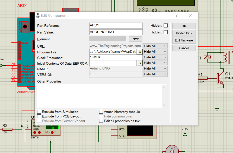
Arduino Hex Code
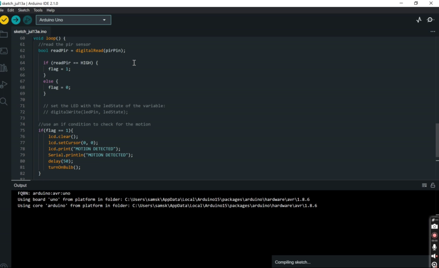
The HEX code is located at the Arduino IDE output console, as stated in the previous post, just copy this address to the HEX code. And paste it into the Arduino Uno by doubleclicking on the components and pasting it into the ‘program file’ input.
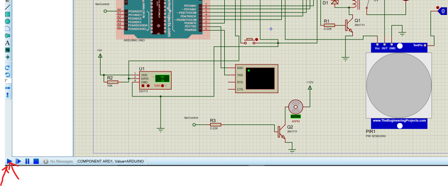
Once this is done, we can proceed to the next step which is actually running the simulation by moving down to the lower panel and click on the play button. This would take just about 1-2 seconds. And the temperature control fan simulation should start running if you got everything connected properly and both the HEX file addresses for the PIR sensor and Arduino Uno set properly.
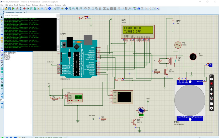
As show below, the simulation would show the temperature of the virtual room and the humidity in degree Celsius and percentage respectively. It will also show the current state of the fan. It is either turned on or off.
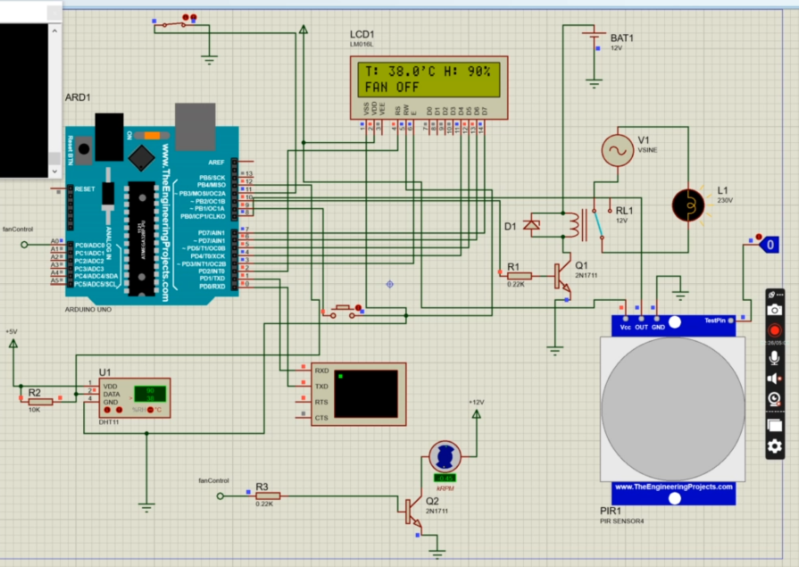
To simulate the temperature changes, we go to the DHT11 sensor component while the simulation is still running. Please note that the simulation may not be running in real time. This is not really a problem since we can still simulate what we intended to do.
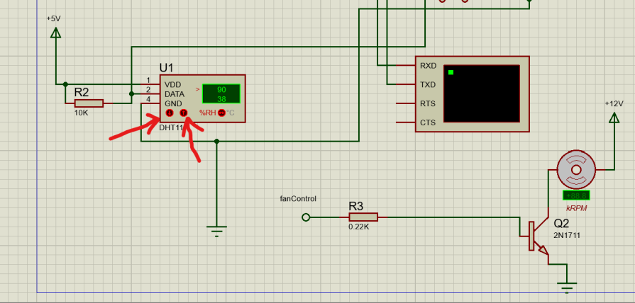
Clicking on any of the two buttons as highlighted out above would change the printed temperature sensed by the DHT11 sensor. The up arrow button increases the temperature whereas the down button decreases the temperature.
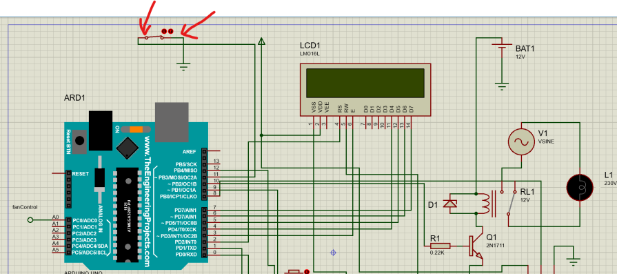
However, if the switch shown above is not turned on (pressed down), the fan won’t start spinning. But if it is as, as shown above, then we can expect the DC fan to rotate. Also, the speed of the fan is controlled by the temperature of the DHT11 sensor. According to the program written, when the temperature is above 37 degree Celsius, the Fan automatically go into activation and would be running at a speed controlled by PWM signal feed into the base of the NPN transistor. And if the temperature is below 35 degrees Celsius, the Fan would automatically stop. These set temperatures are the human body temperatures that are medically know to cause cold and hot.
Conclusion

We have so far, in this temperature control fan simulation post, designed and simulated a home automation system that uses the PIR motion sensor to turn on the virtual room light and also used a digital and humidity sensor DHT11 to control the speed of the fan running in the virtual room. All the components and simulation is running smoothly. Let us know if you remade this on your own or if you added any modifications in the comment section. You can also watch the YouTube video to see the demonstration.

