A feulless generator is a device that generates electricity without the use of fuel. It is powered by a battery, which is charged by a variety of sources, such as solar power, wind power, or kinetic energy. Feulless generators are often touted as a more environmentally friendly alternative to traditional generators, which emit harmful pollutants into the air.
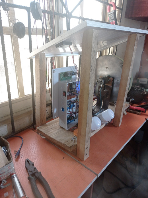
In this project, the watch phrase was to design and construct a feulless generator that would be renewable and rechargeable. Since the project was designed where there is optimum sunshine; the solar based renewable energy source we used. To charge a 12V 7Ah rated battery via a 20W rated PV panel; which in turn would power a DC motor that would drive a dynamo (DC generator) that was responsible for powering the DC loads (the DC bulbs). For easy and better experience of the user, the project was designed to be internet of things (IoT) based. This meant it was controlled and monitored remotely from anywhere on the globe.
The Materials/Components Needed For the Project Design
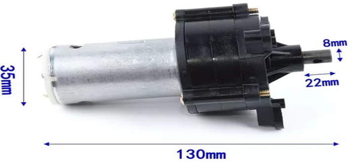
The component displayed above, known as a DC generator, was driven by an electric motor in order to generate electricity. A DC generator was used to model the operation of an Alternator. Ideally, an alternator ought to have been used instead, but it was not used due to its high cost of acquisition, also resulting from its unavailability in the local market. This palm-sized DC generator produces electricity when its armature/rotor copper windings cut through a permanent magnetic field. With the aid of a planetary gear transmission set, the required speed to generate a usable amount of power is easily obtained.
Technical Specifications:
- Minimum output voltage: 5V
- Maximum output Voltage: 24V.
- Maximum output current: 1.5Amps
- Maximum load supply power: 20 Watts
The output voltage varies with the speed of the electric motor driving it.

| Component | Quantity |
| 12V DC motor | 1 |
| NodeMCU dev board | 1 |
| Charge controller | 1 |
| 4 channel relay module | 1 |
| 20W solar panel | 1 |
| 12VDC Electric Generator (Dynamo) | 1 |
| The 90° bend support | 2 |
| Veroboard or Get Smartech PCB Project Board | 1 |
| 1602 LCD module | 1 |
| 3.7V 2.8Ah LiPo battery | 1 |
| LiPo Charging Module | 1 |
| Voltage Sensor Module | 1 |
| 12V 7Ah Rechargeable battery | 1 |
| resistors. 1k, 22k, 100k | many |
| TIP41C NPN Transistor | 1 |
| I2C LCD Module | 1 |
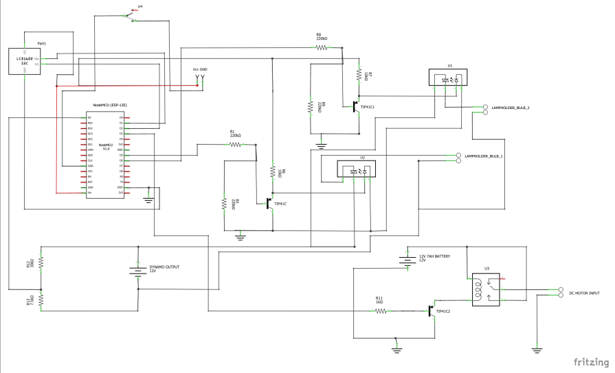
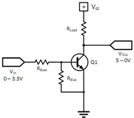
Schematic Diagram for IoT Feulless Generator Project (Control Side)
See the download link to download the pdf file.
DOWNLOAD PDF FILE HERE
Explanation of Feulless Generator Schematic Diagram
The heart of the project design was the NodeMCU. It was important to use a microcontroller that had internet capability. The NodeMCU has the capacity to use its WiFi client access to connect to an existing hotspot with internet. This would give it access to the Blynk server where the remote controls were placed. The relay modules connected to the NodeMCU was working on a logic voltage of 5V. But the GPIO pin can only output 3.3V. We used a transistor logic level inverter to get the 5V HIGH and 0V. How does one convert from one logic level to the other? We used the method of a transistor switch controlled by 3.3-volt logic to drive 5-volt logic. What constitutes a HIGH and a LOW on the ESP32 boards and the modules they control are not the same. For the ESP8266-12E board, a digital pin, whether input or output, is considered in a LOW state for voltages below 0.55 volts and in a HIGH state for voltages between 2.5 and 3.3volts. Whereas the modules a digital pin, whether input or output, is considered in a LOW state for voltages below 1.5 volts and in a HIGH state for voltages between 3 and 5volts. The schematic below solved the problem.
Schematic Diagram for IoT Feulless Generator Project (Mechanical Side)
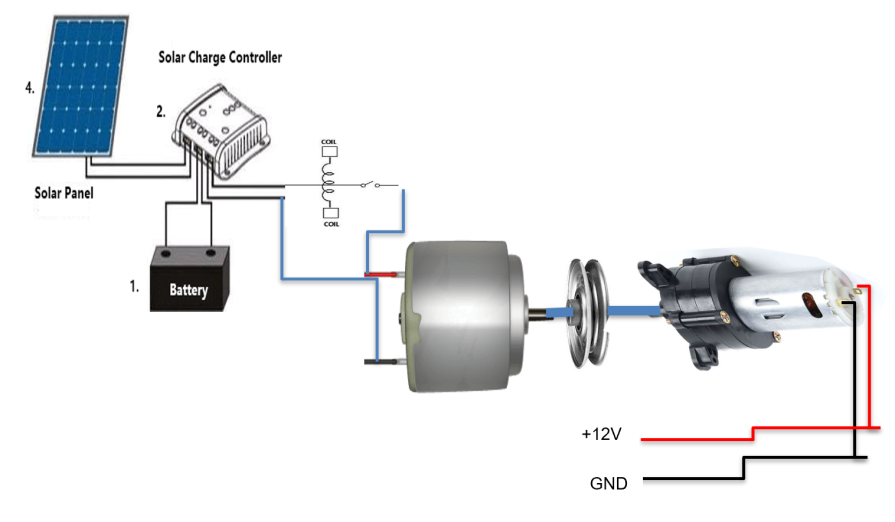
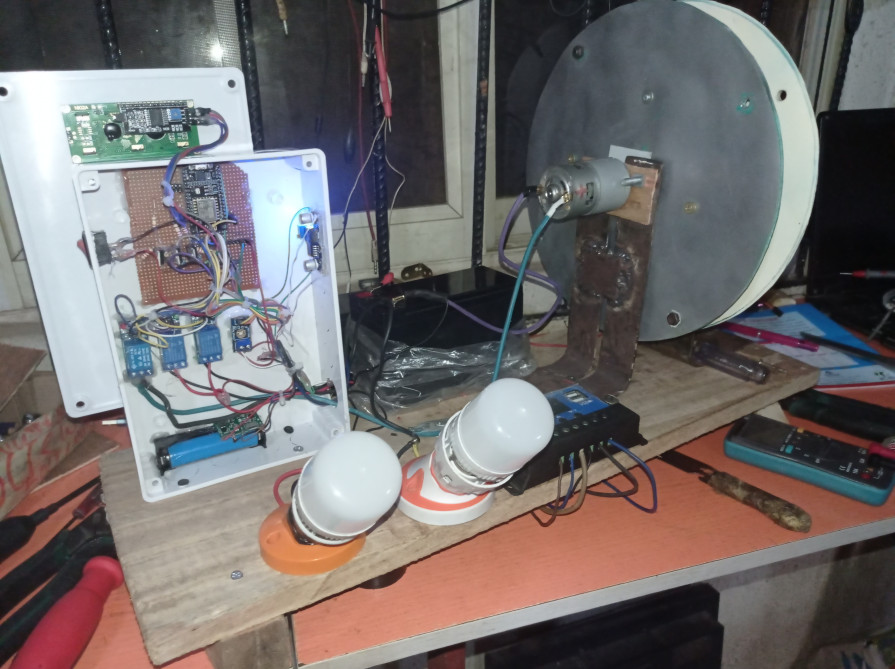
This was done by connecting the PV panel to the charge controller PV input power rails. The 30W PV panel was use to charge the 12V battery. The charge controller has an output for load and this is where the DC motor was connected. A mechanical coupler that was cylindrical in shape and it held the shaft of the DC and the DC electrical generator together. This meant that when the DC motor turns, the shaft of the DC electric motor also turned the shaft of the electric generator. This would output a voltage of 12-24V DC at the output of the DC electric generator.
Designing The IoT Dashboard on Blynk
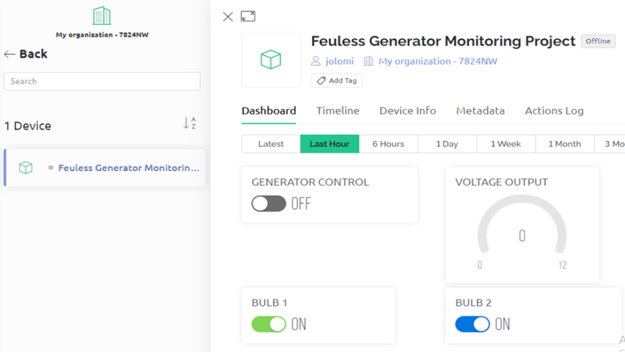
The app was done using Blynk IoT cross platform; as shown above we used the button widget to control the LED. In the LOW (off) state, the LEDs is turned off as shown on the picture on the right hand side. The design worked very well as programmed and the expectations were met. We were also capable to control the two LEDs on the GPIOs with just one button.
Also we added two extra button widgets to control the other bulb while a third widget button was used to control the turning on state of the DC motor. A virtual widget was used to measure the output voltage of the generator.
Programming The Project Design
// Template ID, Device Name and Auth Token are provided by the Blynk.Cloud
// See the Device Info tab, or Template settings
#define BLYNK_TEMPLATE_ID "TMPLA3ZMWUIY"
#define BLYNK_DEVICE_NAME "Feuless Generator Monitoring Project"
#define BLYNK_AUTH_TOKEN "8knfz2FVAOraLJ0OvEqww_vVAdne0m0Y"

// Comment this out to disable prints and save space
#define BLYNK_PRINT Serial


#include <ESP8266WiFi.h>
#include <BlynkSimpleEsp8266.h>
#include <Wire.h>
#include <LiquidCrystal_I2C.h>

char auth[] = BLYNK_AUTH_TOKEN;
//create and instance of the LiquidCrystal, this name will be use as a class to call all the functions of the lcd library
LiquidCrystal_I2C lcd(0x27, 16, 2);

// Your WiFi credentials.
// Set password to "" for open networks.
char ssid[] = "AncII";
char pass[] = "eureka26";

BlynkTimer timer;

int volt;
float voltage;
float divider = 0.936;
float multiFactor = 2.423;

int bulbPin = D3;
int bulbPin2 = D6;
int genStartPin = D5;


// Variables will change:
int ledState = LOW;

// Generally, you should use "unsigned long" for variables that hold time
// The value will quickly become too large for an int to store
unsigned long previousMillis = 0;

// constants won't change:
const long interval = 5000;

void sendSensor(){
    volt = analogRead(A0);// read the input
  float voltage = (volt *5.273)/1023.999;
  voltage = voltage/ divider; // divide by 100 to get the decimal values
  voltage *= multiFactor;
  int voltage1 = round(voltage);
Serial.print(voltage1);
Serial.println();

   // // You can send any value at any time.
  // // Please don't send more that 10 values per second.
  Blynk.virtualWrite(V3, voltage1);
}


BLYNK_WRITE(V0) {
int genWidget = param.asInt();
 Serial.println(genWidget);

if(genWidget == 1){
  digitalWrite(genStartPin, HIGH);
  Serial.println("Gen ON");

}

else{
  digitalWrite(genStartPin, LOW);
  Serial.println("Gen OFF");
}

}

BLYNK_WRITE(V1) {
int bulb1Widget = param.asInt();
 Serial.println(bulb1Widget);

if(bulb1Widget == 1){
  digitalWrite(bulbPin, HIGH);
  Serial.println("bulb 1 ON");
}

else{
  digitalWrite(bulbPin, LOW);
  Serial.println("Bulb 1 OFF");
}
}


BLYNK_WRITE(V2) {
int bulb2Widget = param.asInt();
 Serial.println(bulb2Widget);

if(bulb2Widget == 1){
  digitalWrite(bulbPin2, HIGH);
  Serial.println("bulb 2 ON");
}

else{
  digitalWrite(bulbPin2, LOW);
  Serial.println("bulb 2 OFF");
}
}


void displayVoltage(){
 volt = analogRead(A0);// read the input
  float voltage = (volt *5.273)/1023.999;
  voltage = voltage/ divider; // divide by 100 to get the decimal values
  voltage *= multiFactor;
  int voltage1 = round(voltage);
  lcd.clear();
  lcd.setCursor(1,0);
  lcd.print("VOLTAGE OUTPUT");
  lcd.setCursor(6, 1);
  lcd.print(voltage1);
  lcd.print(" V");
}


void displayBulbState(){
  lcd.clear();
  lcd.setCursor(1,0);
  lcd.print("BULB 1  BULB 2");
  int bulb1Read = digitalRead(bulbPin);
  int bulb2Read = digitalRead(genStartPin);

 if(bulb1Read == HIGH){
  lcd.setCursor(2, 1);
  lcd.print("ON");
 }

 if(bulb1Read == LOW){
  lcd.setCursor(2, 1);
  lcd.print("OFF");
 }

 if(bulb2Read == HIGH){
  lcd.setCursor(10, 1);
  lcd.print("ON");
 }

 if(bulb2Read == LOW){
  lcd.setCursor(10, 1);
  lcd.print("OFF");
 }
}

void setup(){
  // Debug console
  Serial.begin(115200);

    pinMode(bulbPin, OUTPUT);
 pinMode(bulbPin2, OUTPUT);
 pinMode(genStartPin, OUTPUT);

  Blynk.begin(auth, ssid, pass);

  lcd.init();   // initialize the lcd
  Wire.begin(); // Start the I2C
  // Turn on the blacklight and print a message.
  lcd.backlight();//turn on the lcd backlight
  lcd.setCursor(0,0);
  lcd.print("WELCOME MR. JEFF");// ouput the text on the lcd screen
     delay(3000);
     lcd.clear();
    lcd.setCursor(0,0);
    lcd.print("IoT BASED FEULESS");
    lcd.setCursor(3,1);
     lcd.print("GENERATOR");
    delay(3000);
     lcd.clear();
    lcd.setCursor(0,0);
    lcd.print("Connected to:");
    lcd.setCursor(0,1);
     lcd.print(ssid);
     delay(3000);
     lcd.clear();
  // Setup a function to be called every second
  timer.setInterval(1000L, sendSensor);
}


void changeDisplay(){
  unsigned long currentMillis = millis();

  if (currentMillis - previousMillis >= interval) {
    // save the last time you blinked the LED
    previousMillis = currentMillis;

    // if the LED is off turn it on and vice-versa:
    if (ledState == LOW) {
    ledState = HIGH;
    displayVoltage();
    }

    else {
      ledState = LOW;
      displayBulbState();
    }

    // set the LED with the ledState of the variable:
    Serial.println(ledState);
  }
}


void loop(){
   Blynk.run();
  timer.run();
  changeDisplay();

}
Explanation of the Arduino Code
The code began with the setup() function where it began the serial communication protocol at 115200 bits per second. This is the speed at which the microcontroller communicates with the programming laptop. A custom function was created called sendSensor() where an integer variable volt was used to read the analog voltage. Another floating variable voltage was used to calculate the actual voltage. We then printed out this result.
The function BLYNK_WRITE was used to receive commands from the Blynk server this was shown in code line 63, 80 and 96. The functions contained some IF statements such that when the button is pressed and the received integer sent is 1, the NodeMCU would turn on the particular actuator that was assigned to the GPIO pin. However, if the integer sent from the Blynk cloud, this would turn off the actuator that was assigned to the GPIO pin.
Stopping Trip Off Of the Project Design
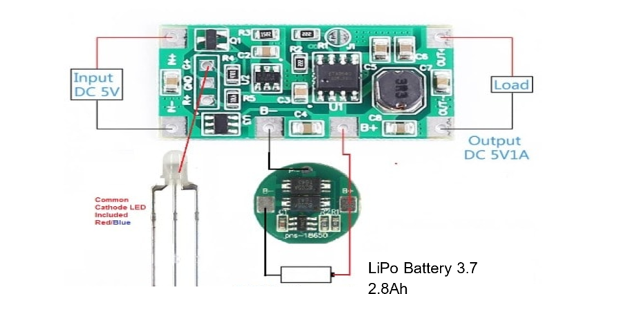
When the project was powered from the 12V 7Ah battery alone, the initial current consumption of the 12V DC motor doesn’t leave any voltage for the MCU and the other components to run. To solve this, a LiPO battery and charge controller was used to get the NodeMCU in a ready state just in case the battery was not fully charged and it has to trip of when the DC motor starts running.
This is LiPo battery was charged by the LiPo charging module. It allowed the input of 5V from a type “B” USB power cord found on the side of the charging module. And has an output for powering load that can be regulated up to 18V. This is because the LiPo charging module has an onboard potentiometer that can use to increase or decrease the output voltage. This was perfect for the design and had to be incorporated into the schematic.

