Tag: Arduino

  • Voltage Sensor Module: Measure Solar Panel Voltage level

    Voltage Sensor Module: Measure Solar Panel Voltage level

    Hello dear reader , in this tutorial we will be talking about using the Voltage Sensor Module to Measure Solar panel voltage level. The Voltage Sensor Module is a voltage sensing module that can be interfaced with an Arduino for measuring DC voltages within 2V – 25V. To read more about the technical details, go to shop.

    Understanding how to accurately measure the voltage level of a solar panel is essential in solar power system design, testing and troubleshooting. One of the simplest and most reliable ways to achieve this is by interfacing a solar panel with an Arduino using a voltage sensor module. This project allows you to observe voltage behavior under different sunlight conditions, compare daytime output fluctuations, and protect your electronics by ensuring incoming voltage stays within safe tolerances. What makes this project especially valuable is that it provides real-time visual and serial feedback of your solar input, making it ideal for students, DIY beginners, and renewable energy enthusiasts who want to learn instrumentation and energy monitoring.

    voltage sensor module
    The voltage sensor

    Components Used for Project Tutorial:

    In this practical, we will be using the Following Component.

    All these components can be bought on our online store. Alternatively, if you can’t find them, leave us a message on WhatsApp or Telegram group for assistance or in the comment section way down below.

    To complete this tutorial, the primary items used include the solar panel serving as the energy source, an Arduino microcontroller functioning as the measurement and processing unit, and the voltage sensor module acting as the interface that allows the panel’s output to be safely read without overloading the Arduino pins. Supporting elements include wires, a breadboard to simplify and organize connections, and a laptop running the Arduino IDE for code uploading and serial monitoring. The components are selected specifically because they are easy to assemble, safe to operate, affordable, reusable across multiple projects, and effective in demonstrating basic principles of solar measurement systems.

    Arduino Voltage Sensor Module: The Principle of Operation

    Arduino Voltage sensor module pinout

    The Voltage sensors are made up of  the following input pinouts (VCC and GND) socket – (which can take in Maximum Voltage of 25v). These pinouts are used for measuring the voltage. On the other side, it has 3 pins which contains (VCC, GND and S where S is the Analog pin that can be connected to Arduino).

    The Arduino voltage sensor module works by taking a higher input voltage and reducing it to a lower scaled value that the Arduino can safely interpret. Internally, the module uses a voltage divider network consisting of precision resistors that proportionally lower the input voltage level based on a fixed ratio. This scaled-down voltage is then fed into one of Arduino’s analog input pins, where it is converted into a digital numerical value by the ADC (Analog-to-Digital Converter). Once the microcontroller receives this reading, software logic reconstructs the original voltage mathematically using the known scale factor of the module. The fundamental idea is that instead of directly connecting the solar panel to the Arduino, the voltage sensor provides safe isolation, monitoring accuracy, and ensures that even fluctuating sunlight peaks do not damage the board.

    The internal circuit of the voltage sensor

    The Arduino Sensor Module contains 2 Resistors 30kΩ and 7.5kΩ that uses the principle voltage divider rule. This is given in the Equation as:

    voltage sensor module equation

    Read up more on this this link. Let us proceed to how to hook this up to an Arduino Uno board and use it to measure DC voltage from a Solar panel up to 24V DC.

    Voltage Sensor Module: Measure Solar Panel Voltage level
    A typical solar panel used in this project

    Solar Panels and How They are Made

    Solar panels use photovoltaic cells, or PV cells, which are made using silicon crystalline wafers similar to the wafers used to make computer processors. The silicon wafers can be either polycrystalline or monocrystalline and are produced using several different manufacturing methods. The most efficient type is monocrystalline (mono) which are manufactured using the well known Czochralski process. This process is more energy-intensive compared to polycrystalline (poly) and therefore more expensive to produce.

    Polycrystalline wafers, on the other hand, are slightly less efficient and are made using several purification processes followed by a simpler, lower cost, casting method. More recently, cast monocrystalline or cast mono cells have been gaining popularity. The reason is due to the lower-cost casting process used to make cast mono cells which is similar to the process used for polycrystalline silicon cells. However, cast-mono wafers are not quite as efficient and pure mono wafers made using the Czochralski process. The various types are namely:

    • Monocrystalline silicon cells – Highest efficiency and highest cost
    • Cast monocrystalline cells – High efficiency and lower cost
    • Polycrystalline silicon cells – Lower efficiency and lowest cost
    Arduino Voltage Sensor Module Measure Solar Panel Voltage level
    The solar panel breakdown part

    Read all about solar panels and how they are manaufactured here. However, for this tutorial our focus is to use Arduino Voltage Sensor Module to Measure Solar Panel Voltage level .

    Voltage Sensor Module: Measure Solar Panel Voltage level

    The Circuit Diagram

    Voltage Sensor Module: Measure Solar Panel Voltage level
    Circuit Diagram for the connection

    To use the Arduino Voltage Sensor Module with Arduino Uno board, the 3 pins of the Voltage sensors are connected to Arduino Uno as shown above. In which, the VCC is connected to 5V. The GND is also connected to the GND of the Arduino. The “S” which is the Analog pins slot is connected to the Analog part on the Arduino board, which could be connected to (A0, A1, A2, A3 and …). For this project we used the A1 analog pin on the Arduino Uno board. To read the battery level for a 3V battery, the above circuit was used.

    The voltage sensor module connects to the solar panel output terminals so that the varying DC voltage created by sunlight can be monitored and analyzed. As sunlight increases, the solar panel generates higher voltage, which the sensor module scales down and sends into the Arduino for processing. The Arduino then analyzes the incoming analog signals and converts them into readable voltage values. This allows the real-time voltage level of the solar panel to be displayed through the serial monitor or an LCD if added. What makes this arrangement significantly useful is that it allows safe measurement without requiring complex test instruments. It also allows you to observe performance characteristics, such as stability, peak voltage, and response under shading. The voltage sensor module therefore acts as an intermediary bridge that simplifies the relationship between renewable energy hardware and the microcontroller software environment.

    Voltage Sensor Module: Measure Solar Panel Voltage Level(Arduino Sketch)

    Measuring the real-time voltage output of a solar panel using an Arduino and a voltage sensor module requires a stable code routine that continuously reads analog values, converts them precisely, and then reports them in volts. The role of the Arduino sketch here is not only to fetch values from the sensor, but also to interpret them, scale them accurately to match the sensor’s voltage divider ratio, and display them in a meaningful way—whether on the Serial Monitor, an LCD module, or transmitted wirelessly to a monitoring dashboard.

    The sensor module typically provides the Arduino with a fraction of the actual solar voltage because the voltage divider inside the module reduces the incoming level into the safe analog-reading range. In the sketch, this divider must be accounted for in the calculation. This is where the calibration constant becomes extremely important. The Arduino receives raw ADC values (0-1023 on most boards), and the sketch interprets these readings against the module’s reduction factor. Without these calculations, the values would appear meaningless and inconsistent, especially when used under variable sunlight conditions.

    In the code, the setup stage prepares the serial communication and initializes the pin used for reading. The loop stage continuously reads, processes, and prints updated voltage data. Some Arduino sketches include minor averaging techniques that stabilize noise that normally appears when sunlight fluctuates due to clouds or shading. A well-structured sketch compensates for this by applying a steady conversion ratio and returning real-time output without sudden spikes.

    It is also possible inside the sketch to define an operational threshold, meaning the system can detect when the solar panel voltage falls below a specified A-level. This allows the Arduino to trigger external relays, alarms, or even automate a switching mechanism that protects batteries from under-voltage. The sketch can therefore serve not only as a data-monitoring tool but as a smart energy-management routine.

    In a more advanced form, the measurement sketch can be extended into a data-logging system where voltage readings are stored with timestamps. From this point the same code can be merged with SD-card modules, IoT dashboards, or Wi-Fi upload functions that track solar performance throughout the day. The fundamental structure remains the same, but the sketch becomes more powerful by giving actionable insight into energy production trends.

    So, the Arduino sketch serves as the interpreter between the voltage sensor module and meaningful human understanding. By transforming electrical values into readable voltage levels, the code makes the system usable by engineers, installers, and students who want a clear view of how their solar panel behaves across varying loads, temperatures and irradiance conditions.

    Explanation of Source Code (Arduino Sketch)

    float PVr1 = 30000.0;
    float PVr2 = 7500.0;
    float batteryVoltSensor, vinBattery;
    const int voltagePinBattery = A0;
    
    void setup() {
      Serial.begin(9600);
       Serial.println("Now in Setup");
    Serial.println("Now exiting Setup function");
    }
    
    void loop(){ 
    Serial.println("Now in loop function");
    
      //now doing calculations
      batteryVoltSensor = analogRead(voltagePinBattery);
     batteryVoltSensor = (batteryVoltSensor * 5.0)/1023.0;
     vinBattery = batteryVoltSensor/(PVr2/(PVr1+PVr2));
    
    Serial.println(vinBattery);
    
    Serial.println("Now exiting loop function");
     delay(1000);
    }
    

    The Arduino sketch is the same as the sketch used for measuring the various battery level voltages. You can take a look at it here. The sketch begins with declaring and assigning floating point variables that takes care of the values of resistors used to form the voltage divider rule. Other variables were declared to later compute the voltage of the PV (solar panel) measured. In the setup() function, the serial communication is began at a baud ate of 9600 bits per second, we printed out some dummy string text to know when we have entered the setup() function and have exited out of it.
    In the loop() function, we carried out the calculation that measured the PV voltage. This was done using the analog pin where the Analog pinout of the Arduino voltage sensor was connected. Then this was multiplied by 5V since the Arduino Development board can take a maximum of 5V of logic voltage. Converted to to actual voltage when divided by 1023 for 16 bits microcontrollers.

    The Arduino sketch programmed for this tutorial continuously samples the analog input pin where the voltage sensor module is attached. Through a mathematical relationship built into the code, the microcontroller converts the raw ADC value into a corresponding real-world voltage reading based on the module’s predetermined division ratio. The code keeps running and updating this value several times per second, allowing the user to observe even slight fluctuations caused by passing clouds or different solar orientations. The sketch also ensures that conversion accuracy is maintained through calibration factors written directly into the script, which refine measurement precision. The final computed voltage is then printed out through the serial monitor of the Arduino IDE, making observation effortless during indoor testing or outdoor data collection sessions.

    Results

    Once powered and connected outdoors, the results show a direct correlation between sunlight intensity and the voltage reported by the Arduino. Voltage values rise during strong sunlight, remain moderate under partial cloud cover, and decline toward evening. Early morning readings appear low and gradually increase as the sun moves to a higher angle. These observations confirm the sensitivity of the panel and the reliability of the voltage sensor circuit in tracking real-time energy production shifts.

    Voltage Sensor Module: Measure Solar Panel Voltage level
    Serial monitor result
    Voltage sensor Module: measure solar panel voltage level
    The final connection

    Explanation of Circuit Diagram

    The circuit diagram for this 21V PV panel uses the same source code (Arduino Sketch) given above. The voltage level of the solar panel for this Arduino Voltage sensor module measure Solar panel voltage level project was observed to increase by up to 22V and it was printed out on a serial monitor.

    The circuit diagram portrays how the solar panel terminals are linked to the voltage sensor input channel, while the module output pin is wired to Arduino’s analog port. Ground reference is consistently shared between the Arduino and the voltage module to stabilize signal flow. The purpose of the diagram is to visually clarify the electrical interaction between the solar generator and the microcontroller system. The layout prioritizes safety by ensuring the solar panel never connects directly to the Arduino analog pins, as that would exceed voltage tolerance. The diagram therefore provides the necessary guidance that ensures the connection style is correct, reliable, and electrically secure.

    Conclusion

    The serial monitor printing shows that we can measure or take the reading of various DC voltage levels of any solar panel that is within the range of 25V MAXIMUM using this voltage sensor. To take measurements above 25V, you have to see our other project tutorial. The readings obtained in this project would then be uploaded to a cloud dashboard using an Arduino Uno and an ESP8266-01 WiFi module.

    So what do you think about this tutorial? Can you reproduce this? or make further modifications to it? Let us know if you tried it and how it built you in the comment section below.
    Thank you.

    Measuring the voltage level of a solar panel using a voltage sensor module and Arduino is more than just observing a fluctuating reading on a screen—it is a powerful process that helps you understand how effectively your panel is converting sunlight into usable electrical output. With a properly calibrated sensor module and a well-structured Arduino sketch, you can monitor daytime variations, detect efficiency drops, troubleshoot irregular charging cycles, and verify panel health in real-world conditions. Whether the goal is experimentation, academic research, or practical solar system maintenance, the process equips you with the insight needed to design better, safer, and more reliable renewable-energy projects.

    As your familiarity grows, the same setup can evolve into automated protections, remote-monitoring systems, and long-term data analytics, turning a simple measurement into valuable engineering intelligence

    Frequently Asked Questions (FAQs)

    1. Can an Arduino measure a solar panel voltage directly without a sensor module?
    No, the Arduino cannot measure high voltage directly. Solar panels often produce voltages far above the Arduino’s safe ADC input limit. The sensor module steps that voltage down safely before measurement.

    2. Why does the sensor reading fluctuate during the day?
    Solar voltage naturally varies with sunlight intensity, shading, panel temperature, angle, and load demand. The fluctuations are normal and reflect real operating conditions.

    3. Does the voltage sensor module measure current as well?
    No, the voltage sensor module measures only voltage. To measure current, you need a current sensor such as ACS712 or a dedicated shunt-based measurement module.

    4. How accurate is the Arduino voltage reading?
    Accuracy depends on module calibration, reference voltage stability, wiring quality, ADC noise, and calculation precision inside the code. It improves significantly with calibration.

    5. Can this setup be used with larger wattage solar panels?
    Yes, as long as the measured voltage remains within the maximum sensor input rating. Higher wattage does not affect measurement safety—voltage does.

    6. Can the measured voltage be displayed on an LCD instead of the serial monitor?
    Yes, the sketch can be modified to display readings on LCD, OLED, Nextion, or even wirelessly on IoT dashboards without changing the measurement principle.

  • Automatic and Remote Control Pedestal fan Arduino (smart fan)

    Automatic and Remote Control Pedestal fan Arduino (smart fan)

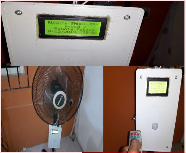
    Hello everyone. In today’s project tutorial, Automatic and Remote Control Pedestal Fan Arduino (smart fan), we will be answering the following questions.

    Have you ever wondered if you could turn your home-standing fan into a smart fan? 

    Do you want to be able to control your pedestal fan using a remote control? perhaps add a  display screen?

    Do you want to see the temperature of your room displayed on this fan? Or perhaps you want to use the room temperature to control the speed of the fan?

    Won’t it be awesome to reverse engineer your pedestal fan and build an automatic and remote control pedestal fan Arduino (smart fan) that would use the room temperature in the room to automatically control the speed of the fan and then lets you control the fan speed at your own will with just any remote control lying around?

    Well, it is very possible and we will do this project tutorial today. Well stay tuned and ensure you read to the end because in this tutorial: we will be discussing how to achieve all of these functionalities inside the automatic control fan. But first, a brief introduction.

    What is a Pedestal Fan?

    A typical pedestal fan
    A typical pedestal fan

    This is an electric and oscillating fan supported by an adjustable, detachable stand with its head above the surface and is adjustable. The sole function of this is to circulate cool breeze around our room. The downside of this electrically powered fan is that its speed regulator control is manually operated.

    What Is Home Automation?

    Home automation is a step toward what is referred to as the “Internet of Things,” it is fun to build and easy if you have the right tools. Home automation is an aspect of IoT called domotics. There are a plenty variety of home automation systems that are available out there and these are equipped with making one’s life easier and more comfortable. Some popular home automation systems include:

    -A home security system that is responsible for monitoring your home and will send out alerts if there is an issue, like a broken window or a theft

    -An energy management system also helps in saving money spent on energy consumption by simply turning off the devices when they are not in use and adjusting the temperature regulators like thermostats.

     -A home entertainment system that can allow one to control his/her home’s lighting, music, and television from any location. These and so many others.

    However, for this project tutorials, our focus is the use a traditional standing fan, a temperature sensor, an Arduino board (standalone version), a TV remote, and other modules to build a smart fan that can measure accurately the temperature of the room, control the speed of the fan in “Auto Mode” using this temperature ranges while offering the user the choice to still override this using a TV remote control to set their own fan speed. Enough said already; let’s dive into designing the project.

    Components parts for Automatic and Remote Control Pedestal fan Arduino (smart fan)

    • Power Supply rated 5V, ≥ 2A or you can build your own here
    • Atmeg328p-pu microcontroller
    • 16MHz crystal oscillator (Newark part number 16C8140)
    • 10nF capacitors
    • A 10kΩ pull-up resistor
    • A reset push button.
    • Dallas temperature sensor DS18B20, maxim part number, 1534C4:
    • A 4.7KΩ pull-up resistor
    • Infrared receiver TSOP1738
    • IR remote controller or any old TV remote(that’s an IR Transmitter)
    • 560Ω 5-band resistor
    • 1µF ceramic capacitor
    • Generic jumper wires: male and female type.
    • 16 × 2 Liquid Crystal Display
    • 10KΩ potentiometer (trimmer)
    • 56OΩ precision resistor
    • LCD connector wires’
    • Header pins
    • 5V 4-channel Relay Module
    • A standing fan

    What is an Infrared (IR) Signal and an IR Receiver Module?

    Infrared radiation that produces Infrared signals or radiations (IR) are actually beams of light, it is that portion of the electromagnetic spectrum that extends from the long wavelength, or red, end of the visible-light range to the microwave range. Invisible to the eye, it can be detected as a sensation of warmth on the skin. Most of the radiation emitted by a moderately heated surface is infrared; it forms a continuous spectrum. Molecular excitation also produces copious infrared radiation but in a discrete spectrum of lines or bands. Everything which produce heat, emits infrared like our human body. Infrared have the same properties as visible light, like it can be focused, reflected and polarized like visible light. IR devices are those photonic components that contains semiconductor materials that are sensitive to IR radiations. They are divided into IR transmitter Light Emitting Diode (LED) and IR Receivers.

    Automatic and Remote Control Pedestal fan Arduino (smart fan)
    Infrared (IR) Remote controller and IR signals

    IR receiver is a sensor that is responsible for capturing the IR signal sent out by the IR emitter or in the case of this project the home TV remote. This exact part used here is shown in the component list to be the common TSOP1638.  It has 3 pinout configuration and can be used either with a programmable device or non-programmable device. In this Automatic and Remote Control Pedestal fan Arduino (smart fan) project, it is used with a programmable microcontroller Atmega328P chip.

    Configuring the IR Receiver Using Arduino.

    The IR Receiver TSOP1738 pinout

    This component as earlier mentioned, is the famous infrared receiver TSOP1738 that has three terminals with the Pin 3 connected to the HIGH of the PSU (+5 Vcc) supply and the Pin 2 connected to the ground terminal(or LOW) of the PSU while the Pin 1 is the output pin. It is called the data pin (or terminal) Do. To stop  the sensor (TSOP1738) from sending fluctuation signals to the MCU due to IR impulses from random sources, a very low capacitive capacitor is connected from the data pin to the ground. This is between 100nF to 33µF. This is shown below.

    Automatic and Remote Control Pedestal fan Arduino (smart fan)
    TSOP1738 Connection to the Arduino Standalone MCU

    Decoding HEX Value Codes From the IR Receiver on Automatic and Remote Control Pedestal fan Arduino (smart fan) project.

    Since this project isn’t based on a non-programmable Remote Control Home Appliance, there is a need to show the IR signals received by the Arduino on the serial monitor. The connection is shown above and the components are assembled on a breadboard.

    A Brief Explanation Of Hex Codes.

    The Decimal number system is also known as Base 10, since it’s comprised of ten numerals (symbolized by 0 through 9). Although we can only represent up to the number 9 by a single decimal digit, it’s possible to reference up to ten items by using zero ( 0) as an index to refer to the first ( 1st) item; thus, the numeral 9 would refer to the tenth ( 10th) item. With two digits we can refer to 100 items (zero through 99). In terms of the number of digits, 10 n (where n is the number of digits) equals the maximum number of items we can refer to. Therefore, the decimal equivalent of the largest binary number we can represent in 6 bits ( 111111 ) can be found as the sum of the first six powers of 2; starting with 2 to the power of zero (2 ^0): 20 + 21 + 2 2 + 23 + 24 + 25 = 1 + 2 + 4 + 8 + 16 + 32 = 63.

    Or, by simply using the formula: 2n – 1 = 64 – 1 = 63.

    To convert any binary number to hexadecimal, that is, base 16, simply order the bits into as many four-bit groups as possible, from the least significant position to the most significant position with any remaining group of only 3, 2, or 1 bits at the far left. Then convert each group to a single hex digit of 0 through 9 or A through F . So, to convert our 6-bit number of 111111 (63 decimal) to hex, we simply group the bits as: 111111 which is easily converted to: 3F hex. An 8-bit or 1-byte hexadecimal number can contain a maximum value of 255 decimal. A 10-bit binary number cannot exceed: 11 11111111 or 3FF  or 1023 decimal. But, the maximum number of Cylinders we can reference in 10 bits is 1024, since we begin counting from zero.

    A 32-bit unsigned integer value can be from 0 to 2(32-1). That is, from 0 to 2147483647.  Similarly, 64-bit unsigned integer value can be from 0 to 2(64-1). Now, 32-bit hex value can be from 0 to 0x7f f f f f f f There will be only 8 digits i.e. 7 f f f f f f f because 1 digit corresponds to 4 bit. Hence 8 digits correspond to 8×4 = 32 bits. So, this means the digits which are followed by 0x are hexadecimal. There are two important aspects to the beauty of using Hexadecimal with computers: First, it can represent 16-bit words in only four Hex digits, or 8-bit bytes in just two.

    Program Code to Decode the IR Signals off the Remote Controller

    //include the IR remote library
    #include <IRremote.h>
    //state the IR input to the MCU
    #define RECV_PIN A1
    //make it recognised to IR Lib
    IRrecv irrecv(RECV_PIN);
    //ask it it get results and save it
    decode_results results;
    
    void setup() {
     //enable the IR
      irrecv.enableIRIn();
    }
    
    void loop(){
    if(irrecv.decode(&results))  {
         irrecv.resume();
        //print the remote results in HEX codes
         Serial.println(results.value, HEX);
      }
    
    HEX Code values for Automatic and Remote Control Pedestal fan Arduino (smart fan)
    HEX Code values displayed on Serial Monitor on the Arduino IDE

    Wit the above program we can use the HEX code of each button to do a certain function on the speed control of the Alternating Current (AC) fan. These HEX value codes would be assigned in the program function later.

    Reverse Engineering The AC Fan Control.

    Fan disassembled
    The fan head

    Steps to Reverse Engineeer Pedestal fan to Automatic and Remote Control Pedestal fan Arduino (smart fan):

    Step 1:

    Remove the fan blade cover. As shown above. The type of AC fa then used in this project has to be opened from the front side.

    Step 2:

    Remove the Fan blades and the locate the screws holding the speed regulator back casing.

    Step 3:

    Unscrew the screws holding the control head cover.

    Step 4:

    The speed regulator knob of pedestal fan
    The fan speed regulator knob

    Remove the regulator knob and the back cover to locate the AC fan coil and the regulator panel. This is the only thing we want to mess with. The speed control knob has 4 input wires going into the coil of the . These are the speed 1 wire, the speed 2 wire, the speed 3 wire, and the neutral wire. These wires are to be connected to a relay module to allow automatic switching between each user button select to the appropriate coil connection terminal.

    labelling the wires properlly
    extend the wires and label them properly

    The Circuit Diagram for Automatic and Remote Control Pedestal fan Arduino (smart fan)

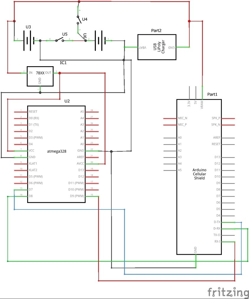
    circuit diagram for Automatic and Remote Control Pedestal fan Arduino (smart fan)
    circuit diagram Automatic and Remote Control Pedestal fan Arduino (smart fan)

    Explanation of Automatic and Remote Control Pedestal Fan with Arduino (smart fan) Circuit Diagram

    As shown above, the circuit used temperature sensor DS18B20 to set for the automated mode for the pedestal fan speed control. The temperature sensor is connected in such a way it used a digital pin on the Atmega328P chip (Arduino Standalone) MCU. The temperature sensor uses 5V and this was ensured it was connected to the correct rated power rail. an enlarged section of the connection is shown below thus:

    DS18B20 temperature sensor connection
    DS18B20 pinout connection

    You can choose to connect your data pin of the temperature sensor to any of your microcontroller pins of your choice, whether analog or digital. Just be sure to define it in your source code. It is also very important to add the 4.7kΩ pullup resistor. If this connection were omitted, the temperature sensor wouldn’t work and the displayed readings would be confusing, like -127°C on the serial monitor window or LCD.

    The relay module is an arrangement of a electromagnetic switches and other discrete linear components that can sense very minimum current input and allow a high voltage to flow across its switch. The module as shown below is designed with an optocoupler which is made up of  LED and phototransistors; signal diodes for relay protection, general purpose NPN transistor and low value resistor.

    four channel relay module circuit diagram
    four channel relay module circuit diagram

    The relay module has four relays that works on the following operation: if we consider the first relay, having switch K1, the anode of the  LED in the optocoupler is connected to the +5v Vcc through a resistor R1. Also the Collector of the transistor Q1 is given a +5v having a common emitter connection to baise the coil of the relay. Current would flow through the anode of the LED and it would glow (although this was not seen since it was encased) thereby biasing base of the transistor which would then conduct, allowing current to flow through the Vcc at the collector and since the base of Q1 is already open through R2 to the -5v(ground). This would in turn energize the coils of the K1 and the pole would change from terminal 3((Normally closed, NC) to terminal 1 (Normally Open, NO) of the Relay. The other relays K2, K3 and K4 works on the same operation.

    Connecting the 1602 LCD Module:

    The liquid crystal display is a display module programmable, economical and can display special characters. A 16×2 LCD means it can display  16 characters per line and there are two of such lines. Each character is displayed in 5×7 pixel matrix. The LCD has two registers namely; Command and Data. The pins and their functions are explained as:

    Register Select (RS): this pin selects Command register when low and Data register when high. Read/Write (R/W): this pin writes to the register when low and reads from the register when high. Enable (E): this pin sends data to the Data pins when a high to low pulse is given to it. Pin 7 to 14 (D4 to D): these are 8-bit pins that are used to send and and receive data to/from the LCD. Pin 15 ( ): this is the positive (+Vcc) backlight of the LED (LED+) of the LCD. This pin is usually connected with a pullup resistor ( ≤ 1kΩ). this is important to limit current flowing in the LEDs of the LCD. Pin 16 (D16): this is the  negative (ground ) −−Vcc pin. It is connected to the ground of the DC power supply.

    Arduino Sketch

    #include <LiquidCrystal.h>
    //state which pins of the MCU connected 4 LCD
    LiquidCrystal lcd(12, 11, 5, 4, 3, 2);
    #include <OneWire.h>
    #include <DallasTemperature.h>
    #include <IRremote.h>
    //state where the input of the temp sensor is connected
    #define ONE_WIRE_BUS A0
    int led1 = 6;
    int led2 = 7;
    int led3 = 8;
    //set the OneWire lib to comm with other bus
    OneWire oneWire(ONE_WIRE_BUS);
    //transfer the data to Dallas temp Lib
    DallasTemperature sensors(&oneWire);
    //state the IR input to the MCU
    #define RECV_PIN A1
    //make it recognised to IR Lib
    IRrecv irrecv(RECV_PIN);
    //ask it it get results and save it
    decode_results results;
    void setup() {
       //begin the LCD to start displaying
      lcd.begin(20,4);
       //enable the IR
      irrecv.enableIRIn();
      //begin the temp sensor
      sensors.begin();
      //outline the inputs and output pins
    pinMode(led1, OUTPUT);
    pinMode(led2, OUTPUT);
    pinMode(led3, OUTPUT);
    //Serial.begin(9600);
    //Display a welcome note
    lcd.setCursor(0, 0);
    lcd.print("Welcome Chinny!");
    lcd.setCursor(0, 1);
    lcd.print("Smart FAN Project");
    delay(3000);
    lcd.setCursor(0, 1);
    lcd.print("Please Wait.......");
    delay(2000);
    lcd.setCursor(0, 1);
    lcd.print("Smart FAN Ready");
    delay(1000);
    }
    void SPEED1()
    {
           digitalWrite(led1, HIGH);
           digitalWrite(led2,LOW);
           digitalWrite(led3, LOW);
           lcd.setCursor(0, 1);
           lcd.print("FAN AT SPEED 1 ");
          //Serial.println("FAN AT SPEED 1");
     }
    void SPEED2()
    {
          digitalWrite(led1, LOW);
          digitalWrite(led2,HIGH);
          digitalWrite(led3, LOW);
          lcd.setCursor(0, 1);
          lcd.print("FAN AT SPEED 2 ");
          //Serial.println("FAN AT SPEED 2");
     }
     void SPEED3()
     {
          digitalWrite(led1, LOW);
          digitalWrite(led2,LOW);
          digitalWrite(led3, HIGH);
          lcd.setCursor(0, 1);
          lcd.print("FAN AT SPEED 3 ");
         // Serial.println("FAN AT SPEED 3");
     }
     void fan_off()
     {
          digitalWrite(led1, LOW);
          digitalWrite(led2,LOW);
          digitalWrite(led3, LOW);
          lcd.setCursor(0, 1);
          lcd.print("FAN TURNED OFF! ");
          //Serial.println("FAN TURNED OFF");
     }
    void tempSensor() {
      if(irrecv.decode(&results)) 
      {
         irrecv.resume();
        //print the remote results in HEX codes
         //Serial.println(results.value, HEX);
      }
      sensors.requestTemperatures();
      float roomTemp = sensors.getTempCByIndex(0);
      lcd.setCursor(0, 0);
      lcd.print("ROOM TEMP:");
      lcd.setCursor(10, 0);
      lcd.print(roomTemp);
      lcd.setCursor(14, 0);
      lcd.print("'C");
      if( roomTemp < 20.00 )
        {
          fan_off();
        }
       else if(roomTemp >= 20.01 && roomTemp <= 30.00)
        {
          SPEED1();
        }
       else if(roomTemp >= 30.01 && roomTemp <= 35.00)
        {
          SPEED2();
        }
       else
        {
          SPEED3();
        }
    }
    void remote()
    {
         if(results.value == 0x1266897) 
         {
          SPEED1();
         }
         else if(results.value == 0x1269867)
         {
          SPEED2();
         }
         else if(results.value == 0x126E817)
         {
          SPEED3();
         }
         else if(results.value == 0x12618E7)
         {
         fan_off();
         }
         else if(results.value == 0x126926D)
         {
          tempSensor();
         }
    }
    void loop() {
      sensors.requestTemperatures();
      float roomTemp = sensors.getTempCByIndex(0);
      lcd.setCursor(0, 0);
      lcd.print("ROOM TEMP:");
      lcd.setCursor(10, 0);
      lcd.print(roomTemp);
      lcd.setCursor(14, 0);
      lcd.print("'C");
      // Serial.print("ROOM TEMP: ");
      // Serial.print("  ");
      //Serial.println(roomTemp);
    if(irrecv.decode(&results)) 
      {
         irrecv.resume();
        //print the remote results in HEX codes
         //Serial.println(results.value, HEX);
      }
         if(results.value == 0x126926D)
         { 
            while((results.value == 0x126926D) ||((results.value != 0x1266897) && (results.value != 0x1269867) && (results.value != 0x126E817) && (results.value != 0x12618E7) && (results.value != 0x126926D)))
            tempSensor(); 
          }
           remote();
     delay(50);
    }
    

    Explanation of Arduino Sketch for Automatic and Remote Control Pedestal fan Arduino (smart fan) Project

    The algorithms programmed into the microcontroller unit (MCU) chip, has two objectives:

    First, the Auto Mode: if, say the room temperature is too hot, it would switch to a speed on the pedestal fan that is the highest speed. this would make the room cold and cozy. However, if it is cold, it would switch to a speed level that is comfortable or turn off totally if it is too cold.


    The User Mode: Mostly, if the user feels that he or she doesn’t like the speed of the fan, he or she can pick up a remote control and select the desired speed of choice; giving it a user enable option.

    The program records and stores the IR signals as HEX Values and it used only Hexadecimal to display the actual Binary bytes of a Memory Dump rather than a huge number of ones and zeros! The second aspect is closely related, whenever it is necessary to convert the Hex representation back into the actual Binary bits, the process is simple enough to be done. For example, FAD7 hex is 1111101011010111 (F=1111, A=1010, D=1101, 7=0111) in Binary.

    Once the IR receiver was configured correctly as drawn in the circuit drawn above and this is powered on; using an old home TV remote as IR transmitter, specific button’s HEX codes were selected and mapped as commands into the MCU to control the fan speed controls. For example, for Speed  1, 0x1266897 is used. But inputting it in an if statement, it makes the MCU know which remote button controls what speed and which function.

    Conclusion

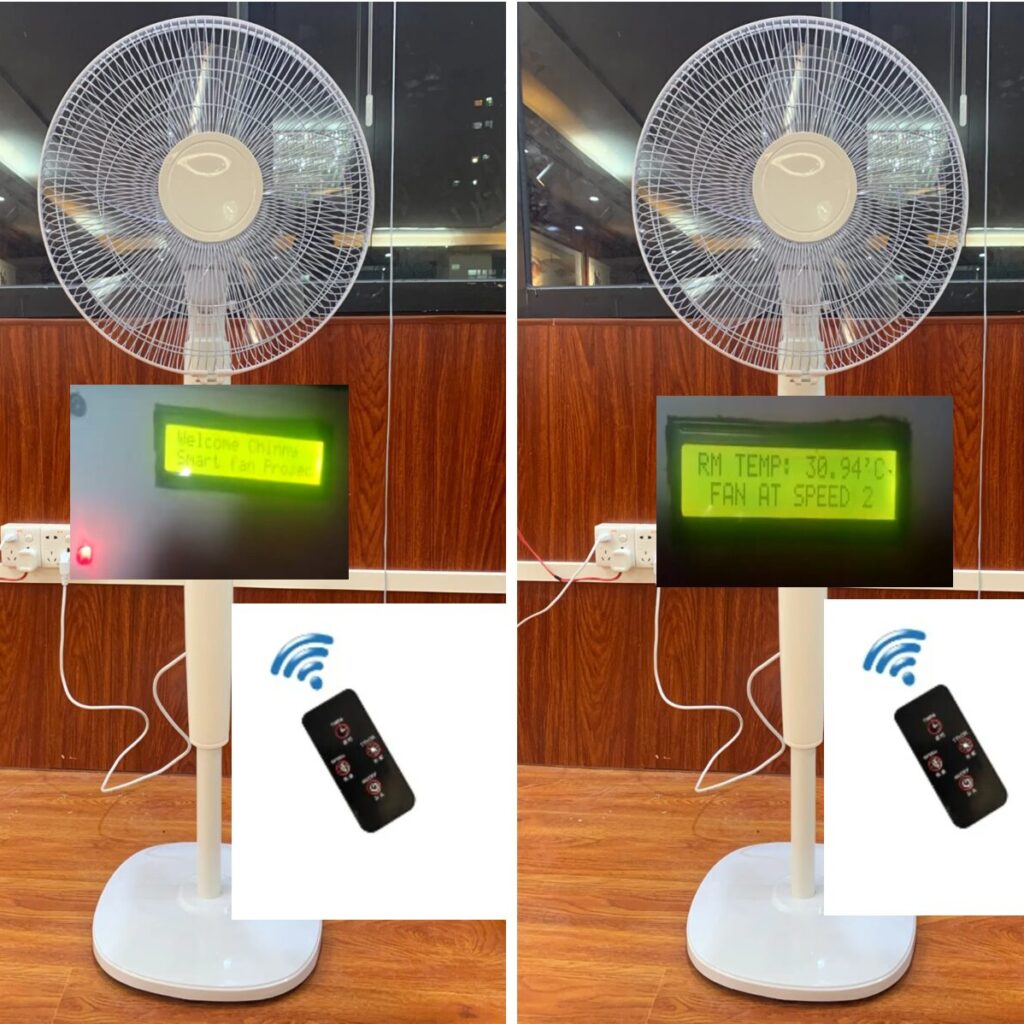
    This remote controlled fan facilitates the operation of fan regulators around the home or office from a distance. It provides a system that is simple to understand and also to operate, a system that would be reliable and easy to maintain, and durable irrespective of its usage. It adds more comfort to everyday living by removing the inconvenience of having to move around to operate a fan regulator. Automatic and Remote Control Pedestal Fan with Arduino (smart fan) is designed with an in-built temperature sensor module that measures the room temperature of the room at every time. It then regulates the fan speed controls based on this temperature in the automatic mode.

    Do you think you can make such a project design? Let us know how you were able pull off such project in the comment section below.

    You can watch the video of the YouTube link below to see the demo of the project in action.

    video demo
  • Arduino Home Automation Using ESP32 Cam and Blynk

    Arduino Home Automation Using ESP32 Cam and Blynk

    Introduction

    Home automation continues to evolve with the help of affordable microcontrollers and IoT platforms. One of the most powerful combinations for beginners and advanced makers is the ESP32-CAM paired with the Blynk mobile app. Together, they allow you to control home appliances remotely while also providing live camera monitoring from anywhere in the world.

    This tutorial is about Arduino Home Automation Using ESP32 CAM and Blynk app. The ESP32 CAM development board is used to control the speed of a rechargeable DC Fan at home using a vertical slider on an android app call the Blynk app. This is the second installment of our Home Automation Project design, you can read the first here. The tutorial will ensure that we control the Fan speed remotely from anywhere around the globe. That means we can run the DC fan at Maximum speed, turn the DC fan off or even keep it going at the speed we desire. We will be listing out the exact components and modules used in this ESP32 CAM project. The explanations of the circuit diagram connection, the ESP32 CAM Blynk code as well as the setting of the design will be well-detailed. Be sure to read through to the end.

    The ESP32 CAM: An Overview.

    The ESP32-CAM is a compact development board built around the ESP32 chip and integrated OV2640 camera. What makes this board exceptional is its ability to combine Wi-Fi, Bluetooth, video streaming, and GPIO control in a tiny, low-cost package.

    With just a few external components and a stable 5V supply, the ESP32-CAM can perform several functions simultaneously: capturing images, streaming video, connecting to the internet, and controlling relays.

    This versatility makes it a perfect choice for home automation projects—especially when video monitoring is part of the design.

    The ESP32 is a powerful microcontroller platform that has been designed for low-cost, high-performance applications. It offers a wide range of features and can be used in a variety of devices, including security cameras. First, we will need to acquire the necessary hardware and software. The ESP32 camera module can be purchased from our online shop.

    The ESP32-CAM Specifications

    The ESP32-CAM is based upon the ESP32-S development board, it has a lot of similarities.  The following specs are outlined for it.

    • Computing power up to 600 DMIPS
    • 520 KB SRAM plus 4 MB PSRAM
    • Multiple Sleep modes
    • Firmware Over the Air (FOTA) upgrades possible
    • 9 GPIO ports
    • 802.11b/g/n Wi-Fi
    • Bluetooth 4.2 with BLE
    • UART, SPI, I2C and PWM interfaces
    • Clock speed up to 160 MHz

    The ESP32 Camera Specifications

    The ESP32-CAM includes an OV2640 camera module. The device also supports OV7670 cameras.  The OV2640 has the following specifications:

    • 2 Megapixel sensor
    • Array size UXGA 1622×1200
    • Output formats include YUV422, YUV420, RGB565, RGB555 and 8-bit compressed data
    • Image transfer rate of 15 to 60 fps

    More details can be looked at here

    Components needed for this tutorial

    Arduino Home Automation Using ESP32 Cam and Blynk: The Schematic Diagram And Breadboard Assembly.

    Arduino Home Automation Using ESP32 Cam and Blynk
    The Breadboard version of the schematic diagram

    Since there are many components soldered already on the bottom of the ESP32 CAM, We recommend using a solderless breadboard when experimenting with this tutorial. The use of female Dupont connectors is recommended.

    The Circuit Diagram

    The circuit diagram of Arduino Home Automation using ESP32 Cam
    The Circuit Diagram

    Explanation of the Circuit Diagram

    The circuit diagram shows that the ESP32 Cam was connected or powered by a 5V input power rail. This can be easily gotten from the ESP32 CAM programming board. This Adaptable CH340 programmer has an output source for 5V and GND.

    The circuit diagram has an indicator LED that is connected to GPIO pin 12 on the ESP32 CAM with a current limiting 220Ω resistor that stops the LED from burning out. The LED indicator here was used to show that the program was working as expected. Later in the code section; a blink-without-delay code will be injected just for aesthetic effect.

    To control the DC fan, we needed to use a transistor that is configured in an amplifier mode. By connecting the DC rechargeable fan in the Common Emitter configuration, we were able to use pulse width modulation (PWM) at the base to control the rate of circular movement (speed) of the DC fan for this Arduino Home Automation Using ESP32 CAM and Blynk app instructible.

    The DC rechargeable fan for this Arduino Home Automation Using ESP32 CAM and Blynk app tutorial operates on 5-9V DC voltage. However, the ESP32 CAM operates on 5V. For this tutorial, we used only the 5V to control the DC fan and the ESP32 CAM. However, if you want to run the DC fan at is maximum speed by using a 9V DC power supply, you may need a DC-Dc buck converter. This would step down the DC voltage to 5V which is suitable for the ESP32 CAM to operate.

    The circuit centers around the ESP32-CAM and a relay module that switches home appliances. The relay is connected to one of the GPIO pins on the ESP32-CAM, while the board itself is powered by a regulated 5V supply.

    In the circuit diagram, the relay controls the live AC line of the appliance. The ESP32-CAM sends a digital HIGH or LOW signal to toggle the relay ON or OFF. Meanwhile, the camera module remains active, allowing remote video monitoring through the Blynk interface.

    A stable power supply is crucial because the ESP32-CAM tends to draw more current during Wi-Fi transmissions. Once everything is connected properly, the system forms a complete IoT-controlled home automation unit.

    Breadboard Assembly for Arduino Home Automation Using ESP32 Cam and Blynk

    Before finalizing the hardware, the entire setup is first assembled on a breadboard. This makes it easier to troubleshoot and test each part of the circuit.

    The ESP32-CAM is placed at the center of the breadboard, while the relay module sits beside it. Jumpers are used to connect 5V, GND, and the control pin between the two modules. The breadboard also hosts the FTDI or USB-to-TTL programmer used during code uploading.

    At this stage, you can verify that the ESP32-CAM powers up correctly, connects to the Wi-Fi network, and communicates with Blynk. Once the relay responds to commands within the Blynk app, the assembly can be moved into a safe housing.

    bread board connection of Arduino Home Automation Using ESP32 Cam and Blynk
    The bread board outlay

    Assembly of the circuit is on a solderless board shown in the picture above. The power rails are maintained as to be expected and preformed jumper wires are used to finish the connections. The DC Rechargeable fan used for this Arduino Home Automation Using ESP32 CAM and Blynk app tutorial was a DC rechargeable hand fan. It was stripped of its internal components and only the Fan motor and blade housing were relevant.

    Setting up the Blynk App for Arduino Home Automation Using ESP32 Cam and Blynk

    Step 1: Download the Blynk app

    download Blynk app
    Download Blynk (Legacy) app

    Open the respective app store for your device and find Blynk legacy. The Blynk legacy version was used for this project. However, if you can’t use this version, kindly leave a comment in the comment section so that we could tell you how to use the latest version of Blynk IoT app for this Arduino Home Automation Using ESP32 CAM and Blynk app tutorial.

    Step 2: Install the Blynk app

    Install Blynk App
    Install the Blynk (legacy) app

    Install the app on your android or iPhone device as shown in the picture above.

    Step 3: Create New project

    After successful installation, sign up or sign in if you already have an account and click on New Project as shown below.

    Create New Project on the Blynk App
    Create New Project on the Blynk App

    Step 4: Pick a name for your new Project

    Create a name for the Blynk project
    Create a name for the Blynk project

    After setting the name of the project click, select your device type as ESP32, and click  create.

    Step 5: Retrieve the token for this Arduino Home Automation Using ESP32 Cam and Blynk project

    Go to your mailbox or to your Blynk dashboard to copy the token. Use this in the Arduino code.

    Step 6: Create the GUI design for Arduino Home Automation Using ESP32 Cam and Blynk project.

    Click on the add button on the upper right side and add the vertical widget. Click on it, select where the desired virtual pin. The PWM output is either 255 or 1023. For this Arduino Home Automation Using ESP32 CAM and Blynk app tutorial, we left it at 1023. Save this and it is done.

    Adding a  Widget on Blink App
    Adding a vertical slider Widget on Blink App

    The Arduino Sketch

    Below is the Arduino code.

    #define BLYNK_PRINT Serial
    #include <WiFi.h>
    #include <WiFiClient.h>
    #include <BlynkSimpleEsp32.h>
    
    const int ledPin =  12;// the number of the LED pin
    
    // Variables will change:
    int ledState = LOW;             // ledState used to set the LED
    
    // Generally, you should use "unsigned long" for variables that hold time
    // The value will quickly become too large for an int to store
    unsigned long previousMillis = 0;        // will store last time LED was updated
    
    // constants won't change:
    const long interval = 1000; 
    
    const int fanPin = 4;
    int fanWidget; 
    
    #define Authorization_key "a6SdaWEnnAoXTmrYhX_GPvQ8hq_fDEvw" //EExmWR-3B8jC7H0ttOzr9qmtAciGW8DR
    #define SSID "***"       // replace with your SSID
    #define Password "***"           //replace with your password
    
    // setting PWM properties
    const int freq = 5000;
    const int ledChannel3 = 0;
    const int resolution = 8;
    
    
    BLYNK_WRITE(V2) {
    fanWidget = param.asInt();
    ledcWrite(ledChannel3, fanWidget);
    Serial.println(fanWidget);
    }
    
    void setup() {  
      Serial.begin(115200);
      delay(10);
      WiFi.begin(SSID, Password);
      while (WiFi.status() != WL_CONNECTED) {
      delay(500);
      Serial.print(".");
      } 
      pinMode(ledPin, OUTPUT);
      ledcSetup(ledChannel3, freq, resolution);  
      // attach the channel to the GPIO to be controlled
      ledcAttachPin(fanPin, ledChannel3);
      Blynk.begin(Authorization_key,SSID,Password);
    }
    
    void blinkky(){
      unsigned long currentMillis = millis();
    
      if (currentMillis - previousMillis >= interval) {
        // save the last time you blinked the LED
        previousMillis = currentMillis;
    
        // if the LED is off turn it on and vice-versa:
        if (ledState == LOW) {
          ledState = HIGH;
        } else {
          ledState = LOW;
        }
    
        // set the LED with the ledState of the variable:
        digitalWrite(ledPin, ledState);
      }
    }
    void loop(){
      blinkky();
        Blynk.run();
      }
    

    Explanation of the Arduino Sketch.

    The Arduino sketch handles the Wi-Fi setup, Blynk communication, and relay control logic. When the ESP32-CAM boots, it connects to your Wi-Fi network using the credentials defined in the code.

    The Blynk library listens for commands sent from the app. When a widget (like a button) is toggled, the ESP32-CAM receives the instruction and switches the relay accordingly. The sketch also configures the camera stream, enabling you to view live footage on your mobile device.

    The code is straightforward: initialize Wi-Fi, connect to Blynk, set pin modes for the relay, and manage the camera server. This structure keeps the sketch clean and easy to expand for multiple relays or sensors.

    The esp32 cam Blynk code made use of some Blynk libraries. The LED pin was set and then the WiFi user name and password were also set. The pulse-width modulation (PWM) properties were set and a function was used to check and control the fan speed.

    Testing the Arduino Home Automation Using ESP32 Cam and Blynk

    Arduino Home Automation Using ESP32 CAM and Blynk app tutorial
    Testing the project

    Upload the Arduino sketch and power the hardware circuitry. Open the Blynk app and press the play button. Once the app gets internet access and it can talk to the ESP32 CAM, it will show connected.  Using the vertical slider we can control the Fan. The Lowest height on the slider will cause the DC fan to turn off while the highest height will make it operate at its maximum speed. Anything in between these two would make the fan run at a speed proportional to the height on the vertical widget on the Blynk app. Please watch the YouTube video below to see the project in action.

    Conclusion.

    In conclusion, we have been able to demonstrate how easy it is to control a DC rechargeable Fan with ESP32 CAM using this post of Arduino Home Automation Using ESP32 CAM and Blynk app . The test above showed that this project worked. Follow the steps shown here to reproduce the project. Just follow the step-by-step guide detailed in this post. As a challenge, you may want to control an alternating current (AC) fan rather than a DC Fan you can try it out or post a question in the comment section so that we can make a post and a video on that. Be sure to check out our previous post on how to control a AC light bulb using ESP32 CAM.

    Please kindly comment about how you feel about this project. Don’t forget to share and like.

    Thank you.

  • How To Generate Electricity using foot-steps with backup charging station (Piezoelectric generator) Project

    How To Generate Electricity using foot-steps with backup charging station (Piezoelectric generator) Project

    In today’s project design, we made a footstep to electricity project that focused on how to generate electricity using foot-steps with a backup charging station (Piezoelectric generator) project. We can use this to charge devices such as smartphones, tablets, and any 5V-rated rechargeable appliance. This foot-step power generation project is a typical example of an electricity generator tile project. And this tutorial goes further than just generating electricity using footsteps but adds a DC-based backup charging station with charging and full charging indicators. Ensure you read until the end to get a full grasp of how it was designed and built. Watch the full video demo here.

    Watch Video tutorial

    Project Materials/Components

    Arduino Nano board Buy here
    Piezoelectric transducer sensors buy here

    Multimeter buy here

    16x4 LCD module buy here

    LCD wire and connector sockets
    10kΩ potentiometer buy here

    USB connector

    Bottle water caps
    Some stranded 1mm wire
    glue sticks buy here

    Glue gun 20W

    3” x 6 “  adaptable box

    Bridge rectifier

    LiPo charging Module

    Wires
    shrink tubes b
    Chat and order for the complete kit of this here

    Introduction

    The piezoelectric sensors, also known as PZT ceramic sensors work on the principle of piezoelectric effect, which means that the sensors can convert mechanical stress (either pressure or stress) into electricity.  Read more about this here.

    The type of PZT ceramic sensors used for this project is shown below. The footstep power generation using piezoelectric sensors project won’t be possible without these PZT ceramic sensors. Each sensor has a pair of wires attached to it. The red-colored wire and the black wire. These should represent the positive and negative polarities of the sensor. However, this isn’t the case when in the piezoelectric generator circuit diagram.

    How To Generate Electricity using foot-steps
    Measuring the voltage generated by each PZT sensor

    When mechanical stress (in the form of applied pressure or impact stress) is applied directly to any of the PZT ceramic sensors, it generates an AC voltage signal. This can be measured by the digital multimeter as shown above. A single piezoelectric sensor of this type can generate up to 6V under the right amount of mechanical stress. This was why this sensor was ideal for our electricity generation from pressure project design.

    Assembling the Piezoelectric Sensors

    The best way to get the most out of the PZT sensors was to assemble or configure the piezoelectric sensors in a node analysis configuration. That is, both series and parallel in configuration. Having a total of 18 PZT ceramic sensors, the connections were made according to the circuit diagram below.

    How To Generate Electricity using foot-steps
    The configuration of the PZT ceramic sensors

    The circuit diagram for the foot step power generation system using piezoelectric sensors showed the connection of the PZT ceramic sensors was connected in both series and parallel modes. There were 3 serially placed PZT sensors, and each of these serial connections (rows) was in turn placed in parallel with 5 other rows of 3 series-connected PZT ceramic sensors. The reason for this mode of configuration was to amplify the voltage output in the series connection and the current in the parallel connection. The series connection of these sensors would increase the overall voltage. A series connection of 3 PZT ceramic sensors can output up to 25V AC when an even force is applied across the sensors. However, the series-connected PZT sensors are susceptible to having an “open circuit” when either of the PZT ceramic sensors breaks or fails during use. Each of these sensors in real life is fragile and can break if the applied pressure is not even around the surface.  This means that the series voltage output won’t be realized because of one damaged sensor in the series connection.
    By using a configuration of both series and parallel, we try to minimize this voltage loss such that, the rows not affected can still output voltage in this how to generate electricity using foot-steps with backup charging station (piezoelectric generator) project or advanced footstep power generation system.

    Rectification and Filtration of the Alternating Current (AC) Voltage.

    How To Generate Electricity using foot-steps
    Adding a Bridge Rectifier Components to the Piezoelectric generator

    The output voltage of the piezoelectric generator is AC-based, and we intend to use it to power DC loads. To achieve this, the bridge rectifier was used to convert the AC signal to DC signal. The bridge rectifier component makes life easier than using the full wave configuration of 4 diodes.  Once the rectification was done, further filtration of AC ripples was done using a 100µF 35V electrolytic capacitor. 

    Piezoelectric sensors naturally generate AC voltage, which must be converted to DC before it can charge a battery or power electronics. This is where the rectification stage comes in.

    A bridge rectifier converts the alternating pulses into a smoothed DC output. However, the rectified voltage still contains ripples, so a large electrolytic capacitor is added as a filter to stabilize the voltage. This filtered DC power becomes the usable output for charging and storage.

    Generate Electricity using foot-steps: Adding Backup battery

    How To Generate Electricity using foot-steps
    3.7V LiPo battery

    The generation of electricity using footstep project design needed a backup battery. This would serve as a backup when the piezoelectric generator was not producing voltage. This backup battery is made up of 3 pieces of 3.7V 3800mA LiPo batteries all connected in series. This battery configuration gave a resultant voltage of 11.1V.

    Recharging Backup Battery.

    To recharge the backup battery, a constant current charging method was used to recharge the backup battery. By practical measurement, the output of this piezoelectric generator circuit diagram was found to range from 10V to 15V. The voltage from the PZT circuit was connected through a current limiting resistor of 1kΩ which was then connected to the now 11.1V LiPo batteries.

    Adding A DC Based Charging Station.

    How To Generate Electricity using foot-steps
    DC-DC Buck converter Module

    The piezoelectric generator has been able to generate DC voltage which can be used to recharge a DC battery that produces 11.1V. To use this voltage level for microcontrollers and DC charging ports; we needed to regulate and stabilize them to 5V. The module used for this job was the DC-DC buck converter. This module allowed us to step down the output of the backup battery to the 5V logic level for the Arduino Nano microcontroller board and the DC charging ports.

    To make the system functional for everyday use, a small DC charging station is added. This station can include USB charging ports or a DC jack for powering portable devices.

    The charging station draws energy from the backup battery, not directly from the piezo sensors. This guarantees stable and consistent output even when no one is stepping on the platform. It effectively turns human motion into a useful energy source for mobile gadgets, LED lights, or small electronics.

    Generate Electricity using Footsteps: Arduino-Based Voltage Monitoring

    The Arduino Nano board was used to measure and display the voltage output by the piezoelectric generator as well as measure and display the voltage level of the backup battery. The circuit diagram was connected as shown below.

    How To Generate Electricity using foot-steps
    Measuring the voltage output of the piezoelectric generator

    The voltage measurement of this how to generate electricity using foot-steps with backup charging station (piezoelectric generator) project was done using the voltage divider rule; this is composed of a pair of known resistor values, R5 and R6, respectively, connected in a series connection. The measurement of the voltage generated by the piezoelectric generator was mostly the voltage drop across R5, as shown in the above circuit diagram. The Vo wire (also called the analog input wire) was connected to the analog pin A0 of the Arduino Nano board. However, because Arduino pins cannot withstand voltage levels above 5V, Caution was taken and a Zener diode of 5V was connected in the reverse direction in parallel to resistor R5. This would ensure that the maximum voltage drop across the Arduino analog pin was 5V.

    Since power from footsteps is intermittent, a backup rechargeable battery is added to store the energy produced by the piezo layer. The battery acts as a reservoir, collecting all incoming power and delivering a stable output whenever needed.

    This storage ensures that even if the walkway is not in continuous use, the system still holds enough energy to power small loads or charge gadgets later. The choice of battery depends on the expected output and usage—Li-ion, NiMH, or sealed lead-acid batteries can all be used.

    To measure the voltage level of the LiPo battery, we used a similar technique. This time, only the values of the resistors connected in series were changed. Since the maximum voltage to be measured and displayed was 12V, Using the series connection of 30k and 7.5k; we formed a voltage sensor. And this is a voltage divider having a ratio of 5 to 1 voltage divider. Hence, there is a reduction by a factor of 5 for any input voltage. The schematic can be drawn below.

    Measurement of Battery Voltage Level Using Arduino
    Measurement of Battery Voltage Level Using Arduino

    The voltage divider rule configuration of resistors that made up the LiPo Battery voltage measurement

    Since we are reading the Arduino analog input pin, which accepts voltages up to 5V. But If the controller had a 3.3V system, the input voltage supplied to it should not be greater than:

      3.3V × 5 = 16.5V

    But Arduino came with AVR chips that have a 10-bit ADC architecture, so this setup simulates a resolution of:

    0.00489V (5V/1023)

    so the minimum voltage of the input voltage detection module is:

                                                                                    0.00489V x 5 = 0.02445V.

    Light Emitting Diodes (LEDs):

    Light Emitting Diode (LED)
    Light Emitting Diode (LED)

    Also called Light Emitting Diodes, LEDs are diodes that convert electrical energy to light energy. The LEDs’ color types used here were Red and Blue LEDs. The Blue LED was to show an indication of charging while the red LED was used to show that the battery was full. However, in the video demonstration, only one LED was used to show when the DC charging port was ready to be used for charging. This red LED would indicate that power has been connected to the system.

    Adding LCD to the Project Design

    LCD circuit diagram connection
    LCD circuit diagram connection

    The LCD module was added to the circuit diagram as shown above; to make the how to generate electricity using foot-steps with backup charging station (Piezoelectric generator) project smarter. The LCD uses the 4-bit communication protocol. This means 4 wires were used for the Data transfer between the Arduino Nano board and the liquid crystal display (LCD) module. These four wire data started from Data wire 7 (D7) of the LCD through D4. The Register Select (RS) and the Enable (E) Pins of the LCD were connected to Digital Pin 2 and 3 respectively. A variable resistor of value 10kΩ was used to adjust the contrast display of the LCD. The variable resistor here was a potentiometer (pot). The wiper pin was connected to the A0 of the LCD. This means the Vcc of the 10 kΩ pot was connected to the 5V, and the ground pin was connected to the GND rail. The voltage drop across the pot is then used to determine the contrast brightness of the display module. Where the Vss and the Vdd pins of the LCD were connected to the 5V and Gnd rails of power respectively. To ensure the LCD came on looking bright, the LED+ and the LED- pins were connected to the power rails using a current limiting resistor of 10kΩ.

    The Complete Circuit Diagram

    How To Generate Electricity using foot-steps
    The breadboard view of the complete circuitry
    The complete circuit diagram (schematic view)
    The complete circuit diagram (schematic view)

    Download clear version of circuit diagram here

    Explanation of the circuit diagram

    The circuit diagram above added a charging indicator using a blue LED, as shown, as well as a full charge red LED indicator. The simple transistor configuration made this possible (although in the video demo, only one LED was used to show the system was ready to connect USB flex).

    The circuit works in stages. The piezo discs form the input layer and feed AC voltage into a bridge rectifier. A capacitor smooths this voltage before delivering it to the battery. The Arduino taps into the battery output for monitoring, while the relay or regulator manages the charging station’s power delivery.

    Each part performs a specific role:

    • Piezo layer generates AC voltage
    • Rectifier converts it
    • Capacitor filters it
    • Battery stores it
    • Arduino, LEDs, and LCD display system activity
    • Charging port outputs usable power

    This layered approach makes the system efficient and easy to understand.

    Assembling the whole Circuitry on A Veroboard

    Using the Veroboard, we soldered the whole components that needed to be soldered on the Veroboard. The Veroboard type used is shown in the picture below. Things like the female header pins were soldered onto it.

    Once the breadboard prototype is tested, the entire design is transferred onto a Veroboard. Components such as the rectifier, capacitors, voltage regulator, and Arduino connectors are soldered neatly into place.

    This final assembly stage ensures durability and prepares the system for real-world use. Proper insulation and spacing are important here, especially where wires connect to the piezo elements or battery terminals.

    Veroboard for soldering
    Veroboard for soldering

    The Perforated Board (strip boards or Veroboard) is a universal permanent circuit board. It is made of one side plastic perforated insulator used to arrange configurations of electronic design to finished work; and underneath, a copper plated line conductor that allows easy soldering. Before using this strip-board, our project was first modeled and tested on a Breadboard, which is a detachable platform, which gives room for error making, removal of components, and reattachment of the components. Unlike the Breadboard, the stripboard is used to solder these components together, and once done, is usually very difficult to remove them without applying heat or destroying the components by the use of force.

    Soldering the Components together
    Soldering the Components together

    The soldering and the attaching of the Arduino Nano development board on the Veroboard. The LCD was connected using the LCD 16-pin wire terminal and female socket. This was then soldered to the Veroboard.

    Soldering and Connecting the LCD
    Soldering and Connecting the LCD

    The Source code for the Design (Arduino Code)

    // include the library code:
    #include <LiquidCrystal.h>
    #include <EEPROM.h>
    #include <BigCrystal.h>
    #include <BigFont.h>
    
    // initialize the library with the numbers of the interface pins
    LiquidCrystal lcd(2, 3, 7, 6, 5, 4);
    BigCrystal bigCrystal(&lcd);
    
    int volt;
    float voltage1;
    float divider = 0.936;
    float piezoDivider = 0.26;
    float multiFactor = 2.423;
    float cell = 11.2;
    float low = 3.2; 
    float full = 10.0;
    
    
    void setup() {
      // set up the LCD's number of columns and rows:
      lcd.begin(16, 4);
       Serial.begin(9600);
    
     //write a welcome msg on lcd
     lcd.setCursor(2,1);
     lcd.print("...WELCOME...");
     lcd.setCursor(3, 2);
     lcd.print("  MR. TOLU ");
     delay(3000);
     lcd.clear();
     lcd.setCursor(4,0);
     lcd.print("FOOT-STEP");
     lcd.setCursor(2, 1);
     lcd.print("PIEZOELECTRIC");
     lcd.setCursor(3, 2);
     lcd.print(" GENERATOR");
     lcd.setCursor(3, 30);
     lcd.print("  PROJECT");
     delay(3000);
     lcd.clear();
       for(int x=0; x<16; x++){
      lcd.setCursor(0,0);
      lcd.print("Checking Battery  ");
      lcd.setCursor(x,1);
      lcd.print("*");
    delay(200);
    }
    lcd.clear();
    }
    
    
    float checkBatVoltage() {
     
       volt = analogRead(A3);// read the input
      float voltage1 = (volt *5.273)/1023.999;
      voltage1 = voltage1/ divider; // divide by 100 to get the decimal values
      voltage1 *= multiFactor;
       
     
     float batPercent = map(voltage1, 3.41, 11.1, 0.0, 100.0);
    Serial.print(batPercent);
    Serial.println();
    batPercent = constrain(batPercent, 0, 99);
    
         char buffer[5]; // buffer to hold the converted variable having a length that is +1 of the variable lentgh
         itoa(batPercent, buffer, 10);
         bigCrystal.printBig(buffer, 0, 0);  
         bigCrystal.print("%");
         int number_count = 1;
        int number_temp = int(batPercent);
        while(number_temp != 0){
          number_count++;
          number_temp /= 10;      
        }
        number_count-=1;
        if(batPercent < 1){number_count = 1;}
        lcd.setCursor(0 + (number_count*4), 0);
        bigCrystal.print(voltage1);
        bigCrystal.print("v  ");
        lcd.setCursor(1 + (number_count*4), 1);
         lcd.print(" BAT   ");
    
       
    Serial.print("  Bat3 = ");
    Serial.print(batPercent);
    Serial.println("%");
    
      Serial.print("Batt Voltage: ");
      Serial.print(voltage1);//print the voltge
      Serial.print("V");
    
      Serial.print(" analogRead: ");
      Serial.println(volt);
      delay(500);
      return voltage1;
    
    
    }
    
    
    float checkPiezoVoltage() {
      int volt = analogRead(A2);// read the input
      float piezoVoltage = (volt *5.273)/1023.999;
      piezoVoltage = piezoVoltage/piezoDivider; // divide by 100 to get the decimal values
      piezoVoltage *= multiFactor;
      piezoVoltage *= 4.76;
      piezoVoltage = int(piezoVoltage);
      Serial.print("Piezo Voltage: ");
      Serial.print(piezoVoltage);//print the voltge
      Serial.print("V");
    
      Serial.print(" analogRead: ");
      Serial.println(volt);
    
     char buffer[5]; // buffer to hold the converted variable having a length that is +1 of the variable lentgh
         itoa(piezoVoltage, buffer, 10);
         bigCrystal.printBig(buffer, 0, 2);  
         bigCrystal.print("V");
         int number_count = 1;
        int number_temp = int(piezoVoltage);
        while(number_temp != 0){
          number_count++;
          number_temp /= 10;      
        }
        number_count-=1;
        if(piezoVoltage < 1){number_count = 1;}
        lcd.setCursor(0 + (number_count*4), 2);
        bigCrystal.print("  Piezo    ");
        lcd.setCursor(1 + (number_count*4), 3);
        lcd.print(" Gen     ");
    
    return piezoVoltage;
      
    }
    
    
    void loop() {
      checkBatVoltage();
      checkPiezoVoltage();
      // set the cursor to column 0, line 1
      // (note: line 1 is the second row, since counting begins with 0):
      
      if(Serial.available())
      {
        char cal = Serial.read();
        if(cal == '+' || cal == 'a')
          divider += multiFactor;
        else if(cal == '-' || cal == 'z')
          divider -= multiFactor;
      }
       delay(50);
    }
    
    long readVcc() {
      long result;
      // Read 1.1V reference against AVcc
      ADMUX = _BV(REFS0) | _BV(MUX3) | _BV(MUX2) | _BV(MUX1);
      delay(2); // Wait for Vref to settle
      ADCSRA |= _BV(ADSC); // Convert
      while (bit_is_set(ADCSRA, ADSC));
      result = ADCL;
      result |= ADCH << 8;
      result = 1126400L / result; // Back-calculate AVcc in mV
      return result;
    }


    Explanation of the code

    Arduino sketch

    The syntax uses special libraries of LCD to display the generated level. Some variables that are universal variables to the code were defined above the setup() function and later used in the function to measure the generated voltage checkPiezoVoltage().

    Arduino sketch to measure piezo generator Voltage Level
    Arduino sketch to measure piezo generator Voltage Level

    In this function, we read the analog voltage from the Vo and then converted it. This is the allowed 5V of the Arduino and the 10bits of the reading. Further calculations were done to adjust and make the reading close to accurate. These readings are then mapped using a map() function. This would allow us to display the voltage at a segmented level. The readings are then printed on the LCD screen using code lines 55 through 59. To make the function repeat itself; we placed the function itself in the loop() function. The loop() function repeatedly executes any code placed inside it.

    Measuring the Battery Level Voltage

    Arduino sketch to measure Battery Voltage Level
    Arduino sketch to measure Battery Voltage Level

    Results

    LCD display of piezoelectric generator output voltage
    LCD display of piezoelectric generator output voltage

    The results obtained are given in the diagram above. Here as seen, before we depressed the voltage generated by the piezoelectric generator was 0V but upon depressing the piezoelectric generator using our feet, we get about 10V DC or above. This voltage is displayed as generated by the piezoelectric generator.

    DC-Based Charging Station

    Charging a mobile phone using the project design
    Charging a mobile phone using the project design

    This was handled by the USB ports shown in the circuit diagram above. Once, any of these ports were connected to a USB charging flex, and connected to a phone. It keeps charging and this result is shown below. As shown in the picture above, the battery level was at 87% and at 10.96V, whereas the piezoelectric generator was at 0V. This was done by the programming sketch written above.

    Conclusion

    And that would be all for this how to generate electricity using foot-steps with backup charging station (Piezoelectric generator) project design. Let us know if you were able to create something similar or better. Don’t forget to leave a comment if you encounter any challenges along the way.

    Thank YOU!!!

  • Visitor Bidirectional Counter Using IR sensors Arduino, Infrared Bidirectional Counter with AC bulb.

    Visitor Bidirectional Counter Using IR sensors Arduino, Infrared Bidirectional Counter with AC bulb.

    This visitor bidirectional counter using IR (infrared) sensors Arduino project uses two Infrared (IR) obstacle sensors to notice the direction of movement; if the direction is from left to right, otherwise known as the entrance, it will count that the person has moved inside a house. And would keep increasing the number of people moving into the house according to this motion direction. Once the entrance count is above one (1), it will turn on an AC bulb. However, if the direction of movement is reversed, that is, from right to left (exit movement), it will decrement the number of people inside the house and will continue to decrement until the count is zero, at which point it will turn off the AC bulb.

    Components/Materials for Visitor Bidirectional Counter Using IR sensors Arduino Project

    For this project design; we will need the following materials:

    Arduino Pro-Mini Dev. Board

    FTDI programmer

    IR obstacle sensor

    5V DC power supply

    Portable AC switch

    Single channel relay module

    LED…2 pieces

    10k resistor….2 pieces (optional)

    16×2 LCD module

    16×2 LCD flex

    You can chat us and order for the full complete project kit

    Circuit Diagram for Project Design

    The circuit diagram for the project is shown below

    Visitor Bidirectional Counter Using IR sensors Arduino
    circuit diagram for the project

    Circuit Diagram Explanation

    The circuit design of the project design shows that a single channel relay module can be constructed using a 5V relay, an NPN transistor like TIP41C, and a 10Kohm resistor and connected as shown in the diagram.

    The usual 4-bit communication protocol was adopted in connecting the LCD to the Arduino Pro-Mini. A 2.7kohm resistor can be used to replace the 10K potentiometer used to adjust the contrast of the 16×2 LCD module.

    The two IR obstacle sensors used to detect entry and exit have their output pins connected to digital pins 2 and 3 respectively on the Arduino Pro-Mini board. The design is then powered by a 5V DC and the following sketch is uploaded into the Pro-Mini board Using the FTDI ISP Programmer.

    The Source Code (Arduino Sketch)

    //include the LCD lib
    #include <LiquidCrystal.h>
    //define where the lcd pins are connected on the A. Pro Mini
    LiquidCrystal lcd(9, 8, 7, 6, 5, 4);
    //define where the IR sensor outputs are connectd
    int irPin1 = 2;
    int irPin2 = 3;
    //define variables
    int count = 0;
    boolean state1 = true;
    boolean state2 = true;
    boolean insideState = false;
    boolean outsideIr = false;
    boolean isPeopleExiting = false;
    int i=1;
    //define actuator pins
    #define relay 10
    #define LED 13
    
    
    void setup() {
      //begin serial monitor
    Serial.begin(9600);
    //define out input and out pin on pro mini board
    pinMode(irPin1, INPUT);
    pinMode(irPin2, INPUT);
    pinMode(relay, OUTPUT);
    pinMode(LED, OUTPUT);
    //begin the lcd module
    lcd.begin(16, 2);
    
    //print a welcome msg on LCD
    //set the cursor first
    lcd.setCursor(0,0);
    lcd.print(" WELCOME DAVID ");
    lcd.setCursor(0,1);
    for(int i= 0; i <15; i++){
      lcd.print(".");
      delay(100);
    }
    //print title of project on lcd
    lcd.setCursor(0,0);
    lcd.print("  BIDIRECTIONAL ");
    lcd.setCursor(0,1);
    lcd.print("COUNTER  PROJECT");
    lcd.clear();
    
    }
    
    
    //this fxn blinks the Red LED when there is entry or exit motion
    void blinkLED(){
       for(int i= 0; i <5; i++){
          digitalWrite(LED, HIGH);
          delay(50);
          digitalWrite(LED, LOW);
          delay(50);
          
       }
    }
    
    
    void loop() {
      Serial.print(!digitalRead(irPin1));
       Serial.print(" ");
      Serial.print(!digitalRead(irPin2));
        Serial.print(" ");
      Serial.println(count);
      delay(300);
    
    if (!digitalRead(irPin1) && i==1 && state1){
         outsideIr=true;
         delay(100);
         i++;
         state1 = false;
      }
    
       if (!digitalRead(irPin2) && i==2 &&   state2){
        blinkLED();
        lcd.clear();
        lcd.setCursor(0, 0);
         lcd.print("ENTERING ROOM");
         outsideIr=true;
         delay(1000);
         i = 1 ;
         count++;
         lcd.clear();
        lcd.setCursor(0, 0);
        lcd.print("    CURRENT");
         lcd.setCursor(0, 1);
         lcd.print("Num in room: ");
         lcd.print(count);
         state2 = false;
      }
    
       if (!digitalRead(irPin2) && i==1 && state2 ){
         outsideIr=true;
         delay(100);
         i = 2 ;
         state2 = false;
      }
    
      if (!digitalRead(irPin1) && i==2 && state1 ){
        blinkLED();
        lcd.clear();
        lcd.setCursor(0, 0);
         lcd.print("LEAVING ROOM");
         outsideIr=true;
         delay(1000);
         count--;
         lcd.clear();
        lcd.setCursor(0, 0);
        lcd.print("    CURRENT");
          lcd.setCursor(0, 1);
           lcd.print("Num In Room: ");
          lcd.println(count);
         i = 1;
         state1 = false;
      }  
    
     
    //condition for AC bulb on
    if(count >= 1){
      digitalWrite(relay, HIGH);
    }
    
    //turn off bulb when nobody is inside
    if(count <= 0){
      digitalWrite(relay, LOW);
      lcd.clear();
      lcd.setCursor(0, 0);
      lcd.print(" NO ONE IN ROOM");
       lcd.setCursor(0, 1);
      lcd.print("LIGHT TURNED OFF");
      count = 0;
    }
    
    
      if (digitalRead(irPin1)){
         state1 = true;
        }
    
         if (digitalRead(irPin2)){
         state2 = true;
        } 
      
    }
    

    Visitor Bidirectional Counter Using IR sensors Arduino Code Explanation

    Basically, what we did above was to define some variables and Boolean states that took care of the changes in the IR sensors when they detect IR emitting obstacles. but we used the “!digitalRead” to show or invert the IR sensor output on the serial monitor. A conditional if statements resets the Boolean states at the end of the loop function.

    Results

    Watch the video demonstration tutorial for more. Kindly leave us a comment below if you reproduce similar project work or a better one than this.

    Conclusion

    We would love to know what you think about the project and you can put a comment to ask for an upgrade of this project. Our social media handles are at the top navigator bar.

    Thank you. See you next time.

  • Solar-Powered Smart Irrigation System with SMS

    Solar-Powered Smart Irrigation System with SMS

    In this project tutorial, we will design and construct a solar-powered smart irrigation system with SMS notification. The system design is an automatic smart project that has the capacity to detect the relative humidity, optimum temperature, and soil moisture level of a garden or farm using special soil moisture sensors and relay this data to an authorized user phone via short message service (SMS). The project design also uses the level of water in the soil to determine when to turn on a DC power pump to pump water into the farm for irrigation purposes automatically. This means it totally eliminates the human labor part in running the irrigation in both arid and well-watered places.

    Material/Components Needed

    In assembling the components and parts needed for the design of this project; we took into consideration the underlined objectives: materials that are not too expensive, readily available, and we could use them to obtain our desired aims.

    • 12V DC pump………………………………………………………………………….1pcs
    • Soil Moisture sensor……………………………………………………………2pcs (or 1)
    • Single Channel Relay Module………………………………………………………1pcs
    • Temperature and humidity sensor module……………………………………..1pcs
    • Microcontroller Unit (Standalone or Arduino made)………………………….1pcs
    • FTDI ISP programming cable………………………………………………………..1pcs
    • 30W PV panel……………………………………………………………………………..1pcs
    • 30A solar charge controller……………………………………………………………1pcs
    • 12V 7Ah backup battery…………………………………………………………………1pcs
    • SIM800L GSM module………………………………………………………………….1pcs
    • Prepaid SIM card and some airtime.

    Theoretical Calculations

    Solar Based Smart Irrigation System with SMS Notification
    power consumption for DC pump and relay module

    Solar Based Smart Irrigation System with SMS Notification: Design the Framework/Woodwork

    The system design had its backbone on the base which shows off the surface where to lay soil for planting of crops. To design the real model of such garden, we used a compressed wood frame.  The wood was first analyzed for structural defects and when ascertained to be minimal; we set out for the dimensioning.

    Sandpapering the design model
    wood dimensioning, sandpapered and cutting

    The wood for the fence of the building was made with dimension of length of about 65cm, the breath  is about 3cm and the height is 8cm. We used a different wood for this.

    The shape of the model garden was rectangular, with no opening. Once we have gotten the fencing structure ready we proceeded to nailing them together. Before this, we polished the base surface and then applied a wood glue to the surface. After a small while, use used a top wrapper to cover it. This was a Glossy Laminate formaica sheets. And this gave is the impression we were looking for. This better choice since we didn’t want the compressed base wood to be getting wet and decaying very quickly as we are pumping water through sprinkling into the garden fam model.

    Solar powered Smart Irrigation System with SMS Notification
    Formaica wrapping on plain wood surface

    After nailing the barricades we have ourselves a look we were looking for as shown below.

    Solar powered Smart Irrigation System with SMS Notification
    The farm garden barricaded

    Next we used wood filler powder to fill some of the minor openings that were between each joining of the woods.

    The garden model
    running irrigation hose through the model garden walls

    We laid the hose around the wall of the fence to form our sprinkling pattern. The hose was further punched at different locations to allow sprinkles of water when the DC pump is turned on.

    The soil moisture sensor and temperature and humidity sensor module (DHT11) are positioned at the best place to take readings. After this, we wire the inside for our soil moisture sensors. We also included the digital and humidity sensor. Then we proceeded to making an external base where we can place out rechargeable battery, solar charge controller and the microcontroller development unit.

    Solar powered Smart Irrigation System with SMS Notification
    The arrangement of the solar irrigation system
    Connectig the 12V DC Pump
    wiring 12V DC pump
    Solar powered Smart Irrigation System with SMS Notification
    schematic diagram of power connection

    The connection in the picture diagram above is almost what we connected for the solar grid in the project design. We however connected the standalone microcontroller development board to the 5V USB terminal above the charge controller.

    First, the battery was connected to the charge controller. After which, we connect the PV array lastly followed by the load which is the DC pump. But until in the actual design, one of the power rails of the DC pump is connected to the single channel relay module. Which would act as a switch for turning on and turning off of the DC pump by the MCU (This is shown in the schematic diagram below).

    The Microcontroller unit (MCU) was enclosed in the 3×6 adaptable box shown below. From this box we connected every other part to the design.

    Encasing the project desing
    powering up the MCU, relay module and SIM800L

    The GSM module. The soil moisture sensors and the dht11 sensor were all encased in a plastic 3×6 patress box. Which is then screwed unto the base of the partition of the wooded base reserved for the power and controls for the garden model. The battery also alongside the solar charge controller is kept on this partition to avoid water from getting into the power leads. We powered the MCU from one of the two 5V output reserves using a USB female socket. While taking a 12V from the output of the solar charge controller then passing it through a DC-Dc buck converter before stepping it down to 3.3V which we used to power the GSM module.

    Constructing the Stand for the PV array:

    Solar Based Smart Irrigation System with SMS Notification
    Screwing the screws that would hold the solar panel at an angle of 45°.
    Solar Based Smart Irrigation System with SMS Notification
    installing the Solar panel on the stand for its position

    Solar-powered Smart Irrigation System with SMS: Circuit Diagram

    Solar Based Smart Irrigation System with SMS Notification
    Complete circuit diagram of the design

    The SIM800L power supply also came from the 12V load output on the charge controller which could only supply the GSM module the rated current (about 2A) it needs to kick-start itself. But we used a DC-DC buck converter for this to ensure that, we stepped it down to 3.4V. The following below is the syntax that was compiled in the Arduino IDE unto the MCU board.

    #include <SerialGSM.h>
    #include <SoftwareSerial.h>
    SerialGSM cell(10,11);
    // Include DHT library and Adafruit Sensor Library
    #include "DHT.h"
    #include <Adafruit_Sensor.h>
    // Pin DHT is connected to
    #define DHTPIN 7
    // Uncomment whatever type of sensor you're using
    #define DHTTYPE DHT11   // DHT 11 
    //#define DHTTYPE DHT22   // DHT 22  (AM2302)
    //#define DHTTYPE DHT21   // DHT 21 (AM2301)
    // Initialize DHT sensor for normal 16mhz Arduino
    DHT dht(DHTPIN, DHTTYPE);
    
    // Create global varibales to store temperature and humidity
    float t; // temperature in celcius
    float f; // temperature in fahrenheit
    float h; // humidity
    float soil; //soil moisture
    String SMS;
    String Invalid; 
    String stat;
    String Pump_State;
    const int pump = 13;
    boolean sendonce=true;
    
    void setup(){  
    //  sensors.begin();
      dht.begin();
      Serial.begin(9600);
      cell.begin(9600);
      cell.Verbose(true);
     //cell.Boot();
      //cell.DeleteAllSMS();
      cell.FwdSMS2Serial();
      delay(2000);
      Serial.println("AM READY FOR YOU\n");
      pinMode(pump, OUTPUT);
      delay(2000);
       }
    boolean readData() {
      //Read humidity
      h = dht.readHumidity();
      // Read temperature as Celsius
      t = dht.readTemperature();
      // Read temperature as Fahrenheit
      f = dht.readTemperature(true);
    
      // Compute temperature values in Celcius
      t = dht.computeHeatIndex(t,h,false);
    
      // Uncomment to compute temperature values in Fahrenheit
      //f = dht.computeHeatIndex(f,h,false);
      
      // Check if any reads failed and exit early (to try again).
      if (isnan(h) || isnan(t) || isnan(f)) {
        Serial.println("Failed to read from DHT sensor!");
        return false;
      }
      Serial.print("Humidity: "); 
      Serial.print(h);
      Serial.print(" %\t");
      Serial.print("Temperature: "); 
      Serial.print(t);
      Serial.print(" *C ");
      //Uncomment to print temperature in Farenheit
      //Serial.print(f);
      //Serial.print(" *F\t");
      return true;
    }
    
    void loop(){
      // Convert the analog reading (which goes from 0 - 1023) to a range (0 - 100):
     soil = analogRead(A2)*100.00/1023.00;
     soil = constrain(soil, 2.00, 100.00);
     soil = map(soil, 100.00, 2.00, 2.00, 100.00);
      
     if (soil <= 65.00)
      {
        digitalWrite(pump, HIGH);
        Pump_State = "ON";
      }
      if ( soil >= 70.00)
      { digitalWrite(pump, LOW);
        Pump_State = "OFF";
      }
      if (cell.ReceiveSMS()){
         Serial.println("NEW SMS ARRIVED");
         delay(100);
         stat = cell.Message();
      if(readData()){
       cell.Rcpt(cell.Sender());
       delay(500);
       Serial.print("Sender: ");
       Serial.println(cell.Sender());
       delay(2000);
       Serial.print("Messsage: ");
       Serial.println(cell.Message());
       delay(2000);
        SMS = ("***SMART FARM DATA***\n__Command Accetped!__\nSee Result Below.\nTEMP: " + String(t) + "*C \nHUM: " + String(h) + "%\nSoil Water: " + String(soil) + "\nPump Status: " + Pump_State + "\nEnd of Report!\nHave a Nice Day.");
        Invalid = "SMS received but I don't recognize your command.\nKindly Contact Mr. Damilare for list of acceptable commands.\nThanks.";
        int m = SMS.length();
        char Send[m + 1];
        strcpy(Send, SMS.c_str()); 
        int i = SMS.length();
        char invalid[i + 1];
        strcpy(invalid, Invalid.c_str()); 
        if(stat == "STATUS"){
            cell.Message(Send);
            }
         else{cell.Message(invalid);} 
        cell.SendSMS();
        delay(2000);
        Serial.println("message sent!\n");
        cell.DeleteAllSMS();
          }
        }
      }


    Source Code Explanation

    The code began with us importing two libraries that were very important; the GSM library and the software serial library. Next we defined where we connected out receiver and transmitter pin of our SIM800L to the MCU using variable name cell. We culled two more libraries for the DHT11 sensor  and defined where we connected the pin. We defined and told the MCU which type of DHT sensor we were using. Other variable names were define to denote temperature and humidity. We defined a String type of variable to hold the SMS to be sent out size. We defined our pump state and its single channel relay pin.

    In our setup() function, we began the Dht11 sensor, and jump started the SIM800L. Once it was ready, we asked it to print out a message (AM READY FOR YOU) on the serial monitor.

    WE used another function, this time a Boolean function readData that wouild be reading and logging the DHT11 sensor. And once the sensor is reading that means it is true and it can always output the data to our serial communication which in turn communicate with the GSM module.

    In the loop() function, the  String SMS is sent out when the incoming text is ‘STATUS’. When the incoming SMS matches the word; STATUS, the MCU prompts the SIM800L to send out the message.

    The if conditions  that are coded after the constrained and mapped values pf the soil moisture sensor allows for us to set the rate at which we can pump the water into the farm. As stated here, the pumps kicks in when the sensor measure a wetness that is below 65.00 and pumps until the wetness goes above 70.00.

    Results and Analysis

    The project, Solar-powered Smart Irrigation System with SMS worked very well as expected when tested after successful compilation of the code into the MCU. Once the SMS that contains the text ‘STATUS’ is sent to the SIM card inserted into the SIM800L module and it confirms reception; it quickly replies with the status of the farm that contains:

    Serial Monitor dispaly of SMS received and sent

    The syntax is supposed to take care of when the incoming SMS doesn’t match the String ‘STATUS’ and reply the sender by telling it that it doesn’t recognize the command. The design can also be sent a command in SMS format of “TURN PUMP ON” and it will turn on the DC pump and would turn it off by itself on the irrigated water level on the garden is enough to avoid flooding of the whole garden model.

    Conclusion

    Now we have shown you how we achieved this project, Solar-powered Smart Irrigation System with SMS Notification. Kindly let us know if you were able to build such similar project or a better version. We will be very glad to help you the best we we can. Let us know if you have any further questions in the comment section. You can also drop a suggestion too! To join the conversation, join our Telegram community, Telegram, Facebook page, Instagram and Twitter.

  • Anti-Theft and Burglar System with SMS Notification

    Anti-Theft and Burglar System with SMS Notification

    This project, Anti-Theft and Burglar System with SMS Notification, is programmed with Arduino with GSM module SIM800L, and has PIR motion sensors and laser trip mechanisms. The anti-theft and burglar system design allows specific users to arm it and disarm it by phone call or short message service (SMS). During the armed state; the systems’ motion sensors and laser mechanisms are activated to sense for intruders senses when there is an intruder within the vicinity. When the system is armed, it informs the user via SMS that it is armed and it is alert for any intrusion. The users can also arm or disarm the system at anytime by calling the system design.

    Materials/Components

    The following components were used in designing this project:

    1. Atmega328P MCU
    2. laser diodes
    3. Light dependent resistors (LDRs)
    4. Passive Infrared Sensors
    5. GSM module, SIM800L
    6. A house model

    To design the Atmega328P MCU, we followed the circuit diagram shown below.

    Circuit of Anti-Theft Design
    Circuit of Anti-Theft Design
    Circuit of Anti-Theft Design

    Download full circuit diagram here or Download it here

    Anti-Theft and Burglar System with SMS Notification: Circuit Design Explanation:

    As shown in the circuit diagram, the design used two PIR sensors; with these, we sensed motions or movements around a vicinity. Using the PIR in a timed sequence and adding a laser trip wire (using laser diodes and LDRs) would help us, as would modelling a house model. Around the windows where burglars have high tendencies of prying the glasses or closures. We added two PIR sensors to window view post. The system would be set to enter “armed state”; which  is the state that the burglar(s) can trip the laser wire that is kept at a respected distance between the window and doors. The tripping would be caused by when the thief breaks the continuous light emitted by the laser onto the surface of the LDR. Then this breaking would make the design to go into the “burglary detect state”. This works a great deal with the PIR and the very close of the stranger to the user’s windows or door. Because in this state, the stranger is almost at the window, and once the PIR detects this illegal motion, it gives off loud varying siren tones through a very loud 12V electronic siren buzzer. And it automatically sends an SMS alert to the user, telling him or her that strange movement occurred at his door or window during such a time as possible while they were not aware or asleep; maybe perhaps gone out. The siren dies down after a while when it is no longer sensing movement within its line of sight.

    Circuit Diagram Mode of Operation:

    For this project, Anti-Theft and Burglar System with SMS Notification. The MCU is selected to be a 28-pin Atmel Atmega328P. The atmeag328P chip has four (4) pins for power. Pins 7 and 20 are for VCC power rails, while pins 8 and 22 are for GND power rails. The hardware reset pin, pin 1 is connected to a 10kΩ precision resistor to keep the pin at 5V HIGH. This pin is an ACTIVE LOW pin. This means the pin would reset the MCU when pulled to the ground (GND) hence the 10kΩ is a pullup resistor. The pin 9 and 10 of the MCU is connected to a 16Mhz crystal oscillator that helps with the pulse clocking and synchronization of internal operations of the MCU. We used the pin 2 and 3 of the MCU for programming it. Since these pins are the UART pins. Also known as the Receiver (Rx) and Transmitter (Tx) pins. These pins would form a crucial part in the FTDI pin connection as we would be using them to communicate between the MCU and the programming PC. Two 22pF capacitors are connected from pin 9 and pin 10 to GND, respectively. This would help in sinking the noise generated by the internal switching of the MCU. To ensure that the MCU accepts programs onto its RAM, we soldered two 100nF  ceramic capacitors between pin 20 and pin 22 and then between pin 1 (RST) and the CTR pin of the FTDI header pins.

    Anti-Theft and Burglar System with SMS Notification: Testing the MCU

    To test if the microcontroller is accepting programs burned into it; we plugged the FTDI ISP programmer into the male header pin ISP input. We open the Arduino IDE and uploaded two programs: The Bare Minimum program and the Blink program.

    Bare Minimum Sourcecode
    void setup() {
    }
    void loop() {
    }
    
    Blink Sourcecode:
    #define testLedPin 13
    void setup() {
    pinMode(testLedPin, OUTPUT);
    }
    
    void loop() {
    digitalWrite(testLedPin, HIGH);
    delay(500);
    digitalWrite(testLedPin, LOW);
    delay(500);
    }
    

    After uploading this source code to the MCU, the LED connected to pin 19 on the MCU starts blinking. We were so sure that the MCU is working to specification.

    We needed a smart display to show the status of the alarm and when it is ‘armed’ and when it is ‘disarmed’. For this function, we used a 16×2 LCD module. The configuration to the MCU is done using 4-bit protocol as shown in the circuit diagram. The Vcc and GND pins of the LCD is connected to 5V and 0V power rails. The Vo is connected to the wiper pin of a 10kΩ potentiometer resistor or a 4.7kΩ connected to Vo then to ground. The register select (RS) pin is connected to pin 13 (PCD08) of the MCU while the enable (E) pin is connected to pin 14 (PCD09). These pins are very important to ensure the LCD screen display the characters that we need it to display. The read/write (R/W) pin of the LCD is grounded. And since we are using a 4-bit communication protocol; we connected four wires from D4 through D7 corresponding to pin 15 through 18 (PCD09 through PCD12) on the MCU. These data pins are very essential and cannot be overlooked when communicating microcontrollers. The LED(+) pin is connected to 5V power rail to ensure backlight brightness comes on when powered on. And finally, the LED(-) pin of the LCD, pin 16 is connected to ground or Vss.

    //The following sourcecode is in C/C++ program using Arduino as IDE
    // include the library code:
    #include <LiquidCrystal.h>
    
    // initialize the library with the numbers of the interface pins
    LiquidCrystal lcd(7, 8, 9, 10, 11, 12);
    
    void setup() {
      // set up the LCD's number of columns and rows:
      lcd.begin(16, 2);
      // Print a message to the LCD.
      lcd.print("hello, world!");
    }
    
    void loop() {
      // set the cursor to column 0, line 1
      // (note: line 1 is the second row, since counting begins with 0):
      lcd.setCursor(0, 1);
      // print the number of seconds since reset:
      lcd.print(millis() / 1000);
    }


    The SIM800L GSM was interfaced as shown in the circuit above. But since the MCU uses 5V logic and the Sim800L module uses 3.3V, we needed a voltage shifter. We connected a DC-DC buck converter to the output of the two LiPo batteries that were in series connection(This was later replaced with a 5V power supply module). The SIM800L connection to the MCU was software serial connection, which means that it could be altered in the programming syntax.

    The idea was to arm and disarm the system using phone calls. After much tinkering and testing, we were able to send SMS from the GSM module and make it receive calls from authorized callers. Thus using this call times to ‘arm’ or ‘disarm’ the system design.

    Finanly, we interfaced the PIR sensors, laser diodes and the LDRs but then we came across a flaw in the design.

    Limitations  and modification of the circuit diagram:

    The Anti-Theft and Burglar System with SMS Notification circuit diagram shown above was limited in function because it had only two PIR sensor and two laser diode to cover the front view and the back view of the compound model. This left a lot of blind spots for burglars to access and penetrate the vicinity. Also, we were already knowing the status of the security design with SMS alert that is sent to our phone; so the LCD display was overdoing it. We needed to cover more view points in the compound. However, this meant more sensors and more pin allocations from the MCU to the sensors. We added one more PIR to the design and two more laser diodes and LDR. However, this was at the cost of the LCD module. The new circuit diagram was thus:

    Circuit of Anti-Theft Design
    final circuit diagram

    Further adjustment made was to remove the relay for switch the 12V high pitch siren buzzer and use loud piezo buzzer instead and using transistor as a solid state switch to switch from the microcontroller. This reduced the rate of power consumption of the components and since this was a prototype, it was very ideal not to deafen the observers during display.

    CONSTRUCTING THE HOUSE MODEL

    Anti-Theft and Burglar System with SMS Notification
    The compound model

    The design for the Anti-Theft and Burglar System with SMS Notification project was modelled after a bungalow house. The design began with dimensioning and measurement of the house outlook. We envisioned that we needed a compound with four (4) sides. Hence we made a dimension of a wooden rectangular base of length 65cm x 60cm.

    Still modelling off for the Anti-Theft and Burglar System with SMS Notification, The wooden base was cut with a hand saw and it was sand-papered according to ensure smoothness and splinters from entering the hands since hand gloves were not provided in the workshop. After this process, the vertical side braces which would act as the fences were cut out. For the width side of the fences, a pair of soft wood with dimensions: 60cm x 7cm x 2cm. The top of the soft wood is being installed nails and then barb-wired modeling it off from a real fence. Once this was completed; the gating system was also cut of. This has a dimension of 20cm x 2cm.

    Anti-Theft and Burglar System with SMS Notification
    The front view

    A model house is then placed inside this compound where the sensors are attached for this Anti-Theft and Burglar System with SMS Notification project. The roof of the model house is a transparent plastic glass, which helps to view the circuit design from the top view angle.

    Anti-Theft and Burglar System with SMS Notification
    The final outlook model
    #include <EEPROM.h>
    #include <SoftwareSerial.h>
    SoftwareSerial cell(11, 12);
    
    const char number1[] = {"09033827773"};
    const char number2[] = {"07062174135"};
    const char number3[] = {"*********"};
    
    int8_t answer;
    char aux_string[30];
    char phone_number[15];
    char received[15];
    int length = 11;
    String caller;
    int counter = 0;
    boolean Armed = EEPROM.read(0);
    char status = "ACTIVE";
    
    int pirPin1 = 6; 
    int pirPin2 = 9;
    int pirPin3 = 10;
      
    int ldrRoofPin = A0;
    int ldrFrontPin = A1;
    int ldrleftPin = A5;
    int ldrRightPin = A3;
    
    // Output Pins
    int laserActivePin = A4;
    int AlarmPin = 13;
    
    int ldrTopSense, ldrLeftSense, ldrRightSense, ldrFrontSense; 
    
    boolean pir1Sense = true;
    boolean pir2Sense = true;
    boolean pir3Sense = true;
    
    void setup() {
      //tell MCU ur outputs
      pinMode(laserActivePin, OUTPUT);
        pinMode(AlarmPin, OUTPUT);
          
      //tell MCU ur inputs
      pinMode(pirPin1, INPUT);
      pinMode(pirPin2, INPUT);
      pinMode(pirPin3, INPUT);
    
      //off Alarm
      digitalWrite(AlarmPin, LOW);
        //Begin serial communication with Arduino and Arduino IDE (Serial Monitor)
      Serial.begin(4800);
      //Begin serial communication with Arduino and SIM800L
      cell.begin(4800);
      Serial.println("Initializing...");  
      delay(1000);
      while ( (sendATcommand("AT+CREG?", "+CREG: 0,1", 500) ||
               sendATcommand("AT+CREG?", "+CREG: 0,5", 500)) == 0 );
      Serial.println("Connected to Mobile Network...");
      
    
    }
    
    void loop(){
      pir1Sense = digitalRead(pirPin1);
       pir2Sense = digitalRead(pirPin2);
       pir3Sense = digitalRead(pirPin3);
    
     ldrTopSense = analogRead(ldrRoofPin);
     ldrLeftSense = analogRead(ldrleftPin);
     ldrRightSense = analogRead(ldrRightPin);
     ldrFrontSense = analogRead(ldrFrontPin);
    
    Serial.print(pir1Sense);
    Serial.print("  ");
    Serial.print(pir2Sense);
    Serial.print("  ");
    Serial.println(pir3Sense);
    
    Serial.print(ldrTopSense);
    Serial.print("  ");
    Serial.print(ldrFrontSense); 
    Serial.print("  ");
    Serial.print(ldrLeftSense);
    Serial.print("  ");
    Serial.println(ldrRightSense);  
    
    //program is allways waiting for a +CLIP to confirm a call was received
      //it will receive a +CLIP command for every ring the calling phone does
      while (answer = sendATcommand("", "+CLIP", 1000)) {
        //answer is 1 if sendATcommand detects +CLIP
        if (answer == 1)
        {
          counter ++; // INCREMENT THIS VARIABLE FOR EACH RING.
          Serial.println("Incoming call");
          Serial.println(counter);
          for (int i = 0; i < 15; i++) {
            //read the incoming byte:
            while (cell.available() == 0)
            { delay (50); }
            //stores phone number
            received[i] = cell.read();
          }
          cell.flush();
          byte j = 0;
          //phone number comes after quotes (") so discard all bytes until find'em
          while (received[j] != '"') j++;
          j++;
          for (byte i = 0; i < length; i++) {
            phone_number[i] = received[i + j];
          }
        }
        for (int i = 0; i < length; i++) {
          // Print phone number:
          Serial.print(phone_number[i]);
          caller += phone_number[i];
             }
        Serial.println("\n>>>" + caller);
        
        //After 3 RINGs compare the caller ID with the authorized list then take decisions.
        if(counter > 3){
        if(caller != number1 && caller != number2 && caller != number3){
          Serial.println("Unknown Caller"); 
          sendATcommand("ATA", "OK", 500);
          Serial.println("I just picked to HangUp"); 
          sendATcommand("ATH", "OK", 500);
          }
        else {
           Serial.println("Authorized Caller");
           sendATcommand("ATH", "OK", 500);
           Serial.print("I Know You MASTER, no need to pick."); 
           Armed = !Armed;
           EEPROM.update(0, Armed); 
           counter = 0;
       
       if(Armed){
        Serial.print("Armed ");
         sendSMS("07062174135", "Alarm Armed. \nThank You.");
         sendSMS("09033827773", "Alarm Armed. \nThank You.");
         updateSerial();
      delay(500);
        delay(3000);
       }
       else{
        Serial.print("Not Armed");
        sendSMS("07062174135", "Alarm Disarmed. \nThank You.");
        sendSMS("09033827773", "Alarm Disarmed. \nThank You.");
        updateSerial();
      delay(500);
       delay(3000);
       }
      
       }
           }
      } 
    
     if(Armed == 1){
        Serial.println("\nArmed");
    analogWrite(laserActivePin, 225);
    digitalWrite(AlarmPin, LOW);
       Serial.println("LASER ON");
        while(pir1Sense){
                analogWrite(AlarmPin, 255);
                Serial.println("\nALARM now ACTIVE");
                sendSMS("07062174135", "Intrusion Detected At left Window.");
                sendSMS("09033827773", "Intrusion Detected At left Window.");
                updateSerial();
                return;
             }
          while(pir2Sense){
          analogWrite(AlarmPin, 255);
          Serial.println("\nALARM now ACTIVE");
          sendSMS("07062174135", "Intrusion Detected At Front Entrance.");
          sendSMS("09033827773", "Intrusion Detected At Front Entrance.");
          updateSerial();
          return;
         }
       while(pir3Sense){
        analogWrite(AlarmPin, 255);
        Serial.println("\nALARM now ACTIVE");
         sendSMS("07062174135", "Intrusion Detected At Right Window.");
         sendSMS("09033827773", "Intrusion Detected At Right Window.");
         updateSerial();
        return;
       } 
       
       //check when it is dark
           if(ldrLeftSense < 950) {
             digitalWrite(AlarmPin, HIGH);
        Serial.println("\nALARM now ACTIVE");
        sendSMS("07062174135", "Laser Tripped At Right Fence Side.");
        sendSMS("09033827773", "Laser Tripped At Right Fence Side.");
        updateSerial();
        return;    
        }
      if(ldrRightSense < 950){
          digitalWrite(AlarmPin, HIGH);
        Serial.println("\nALARM now ACTIVE");
         sendSMS("07062174135", "Laser Tripped At Left Fence Side.");
         sendSMS("09033827773", "Laser Tripped At Left Fence Side.");
         updateSerial();
         return;
      }
    
      if(ldrFrontSense < 950){
       digitalWrite(AlarmPin, HIGH);
        Serial.println("\nALARM now ACTIVE");
         sendSMS("07062174135", "Laser Tripped At Front Fence Side."); 
         sendSMS("09033827773", "Laser Tripped At Front Fence Side.");
         updateSerial();
         return;   
      } 
      }
       
         if(Armed == 0){
          Serial.println("\n Not Armed");
    analogWrite(laserActivePin, 0);
    digitalWrite(AlarmPin, LOW);
       Serial.println("LASER OFF");
         }
    caller = "";
     }
    
    
     void sendSMS(char receiver[11], char content[140])
     { 
       cell.println("AT+CMGF=1");
       delay(1000);
       cell.print("AT+CMGS=");
       delay(5);
       cell.print(char(34));
       delay(5);
       cell.print(receiver);
       delay(5);
       cell.println(char(34));
       delay(5);
       cell.print(content);
       delay(50);
       cell.println(char(26));
       delay(2000);
       Serial.println("Done");
       delay(3000);   
    }
    
    
    void updateSerial()
    {
      delay(5);
      while (Serial.available()) 
      {
        cell.write(Serial.read());//Forward what Serial received to Software Serial Port
      }
      while(cell.available()) 
      {
     Serial.write(cell.read());//Forward what Software Serial received to Serial Port
      }
    }


    int8_t sendATcommand(char* ATcommand, char* expected_answer, unsigned int timeout) {
    
      uint8_t x = 0,  answer = 0;
      char response[100];
      unsigned long previous;
    
      memset(response, '\0', 100);    // Initialice the string
    
      delay(100);
    
      while ( cell.available() > 0) cell.read();   // Clean the input buffer
    
      cell.println(ATcommand);    // Send the AT command
    
      x = 0;
      previous = millis();
    
      // this loop waits for the answer
      do {
        // if there are data in the UART input buffer, reads it and checks for the asnwer
        if (cell.available() != 0) {
          response[x] = cell.read();
          x++;
          // check if the desired answer is in the response of the module
          if (strstr(response, expected_answer) != NULL)
          {
            answer = 1;
          }
        }
        // Waits for the asnwer with time out
      } while ((answer == 0) && ((millis() - previous) < timeout));
    
      return answer;
    }
    

    Conclusion

    Now we have shown you how we achieved this project, Anti-Theft and Burglar System with SMS Notification. Kindly let us know if you were able to build such similar project or a better version. We will be very glad to help you the best we we can. Let us know if you have any further questions in the comment section. You can also drop a suggestion too! To join the conversation, join our Telegram community, Telegram, Facebook page, Instagram and Twitter.

    Read More

  • How to Design IoT Based Air Quality Monitoring For COPD Patients

    How to Design IoT Based Air Quality Monitoring For COPD Patients

    This project tutorial, How to Design IoT Based Air Quality Monitoring For COPD Patient is about how to design an IoT based air quality monitor for Chronic Obstructive Pulmonary Disease (COPD) patients. The system design measures the level of toxicity in the breathable air around people and detects certain high traces of contaminants like hydrogen sulphide (H2S), carbon monoxide (CO), Carbon dioxide gas (CO2), ammonia gas (NH3) and methane gas (CH4) . According to research, these gases comprise some of the heavy contaminant gases that affect COPD patients a lot.

    The Proposed Algorithm

    How to Design IoT Based Air Quality Monitoring For COPD Patients

    The Circuit Diagram

    The microcontroller unit (MCU) is designed using the Atmega328P-P microcontroller chip. Read more project tutorials using Atmega328P. The schematic diagram of this project is shown below.

    How to Design IoT Based Air Quality Monitoring For COPD Patients
    Circuit Diagram of the device

    We will program it using an FTDI flex and Arduino IDE. The circuit diagram above sowed that we connected an external 16Mhz crystal with a pair of 22pF capacitors to suppress noise of MCU internal switching. To enable ISP programming; we connected 100nF capacitor to the RTS pinout for resetting when programing. We also connected another 100nF the power rails. This would make the programming go smoother.

    FTDI cable
    FTDI cable

    The indicator LED is optional and can be added to know when the program was successfully uploaded.

    How to Design IoT Based Air Quality Monitoring For COPD Patients
    Circuit diagram with two gas sensors: MQ135 and MQ136

    The two sensors are connected to he analog pins of the Atmega328P MCU standalone board. We also connected the a buzzer o notify us when the air contamination spikes high and unfit for breathing. The LCD module is connected using 4-bit configuration. The Register Select (RS) is connected to digital pin 7 (D7) of the Atmega328P MCU, Enable Pin (E) is connected to D8, while D4 through D7 of the LCD module is connected to D6 through D3 of the MCU IC.

    The ESP8266-01 (ESP-01) WiFi module is is connected as a Station (STA) tot he MCU using software serial communication protocol. The Transmitter (Tx) pin of the ESp-01 is connected to the D9 of the MCU while the Receiver (Rx) pin is connected to D10 of the MCU. The reset pin of ESP-01 is connected to D11 while the Enable and Vcc pins are connected to 3.3V. The GND is connected to the GND power rail.

    In testing and configuring the ESP-01 module. We connected the the Tx and Rx of the ESP-01 to the Tx and Rx of the MCU, then we changed the baud rate to 115200bps by opening the serial monitor on the Arduino IDE.

    Arduino Source Code

    We opened a blank sketch or Bare Minimum Sketch example and uploaded it to the System.

    bare minimum sketch

    We type in the top pane: AT

    The system would return: OK.

    This would show that the system is communicating with he ESP-01 module. We type: AT+CWJAP=”USERNAME OF WIFI”,”PASSWORD OF WIFI” then hit enter.

    This will display that it is connected to the WiFi and also show that it has been assigned an IP address.

    After this; we can connect the ESP-01 as shown in the circuit diagram above and powered it up. It would reflect on our phones or router that we are using as WiFi access points.

    Before uploading the code below to the design: we have to setup our Thingspeak channel. click here to read about setting a Thingspeak channel and account.

    <!-- wp:code -->
    <pre class="wp-block-code"><code>//Program Code for IoT Based Air Quality for COPD Patient
    //include type of comm lib
    #include &lt;SoftwareSerial.h&gt;
    //type of comm pins connctn
    SoftwareSerial EspSerial(9, 10);
    //include the libs
    #include &lt;LiquidCrystal.h&gt;
    LiquidCrystal lcd(7, 8, 6, 5, 4, 3);
    
    //include write key of thingspeak 
    String statusChWriteKey = "HREVVINHITJ179YP"; 
    
    //define wia ESP-01 pin is connected
    #define HARDWARE_RESET 11
    
    //how many microseconds to write
    long writeTimingSeconds = 17;
    long startWriteTiming = 0;
    long elapsedWriteTime = 0;
    
    boolean error;
    
    //declare the sensor input analog pins
    const int MQ135_PIN = A0;
    const int MQ136_PIN = A1;
    
    int MQ135RL_VAlUE = 20;
    int MQ136RL_VAlUE = 20;                                        
    float MQ135RO_CLEAN_AIR_FACTOR = 3.86;
    float MQ136RO_CLEAN_AIR_FACTOR = 3.78;
    
    #define buzzer 12
    #define LED 13
    
    int MQ135CALIBARAION_SAMPLE_TIMES = 50;                    
    int MQ135CALIBRATION_SAMPLE_INTERVAL = 50;        
    int MQ135READ_SAMPLE_INTERVAL = 50;                       
    int MQ135READ_SAMPLE_TIMES = 5;
    
    int MQ136CALIBARAION_SAMPLE_TIMES = 50;                    
    int MQ136CALIBRATION_SAMPLE_INTERVAL = 50;        
    int MQ136READ_SAMPLE_INTERVAL = 50;                       
    int MQ136READ_SAMPLE_TIMES = 5; 
    
    #define GAS_CH4   0     //our aim is: mq-135 for CO2, Methane &amp; NH3,  mq-136 = H2S,
    #define GAS_CO2    1
    #define GAS_NH3   3
    #define GAS_H2S   4  
    
    float CH4Curve&#91;3]   = {2.3,0.51,-0.39};   //pt.1 (log 200, log3.2), pt.2(log 10000, log.69) and slope m= (y2-y1)/(x2-x1) then we choose pt.1
    float CO2Curve&#91;3]    = {2.3,0.72,-0.34};   //pt.1 (log200, log5.3), pt.2 (log10000, log1.5)
    float NH3Curve&#91;3]   = {1.0,0.23,-0.15};   //pt.1 (log10, log1.7), pt.2(log100, log1.2)
    float H2SCurve&#91;3]   = {1.3,0.11,-0.32};   //pt.1 (log20, log1.3) &amp;&amp; pt.2(log100, log0.78) 
    
    float MQ135Ro = 10; 
    float MQ136Ro = 10;
    
    long iPPM_CH4 = 0;
      long iPPM_CO2 = 0;
      long iPPM_NH3 = 0;
      long iPPM_H2S = 0;
     
    void setup() {
      pinMode(MQ135_PIN, INPUT);
      pinMode(MQ136_PIN, INPUT);
      pinMode(buzzer, OUTPUT);
      pinMode(HARDWARE_RESET, OUTPUT);
      pinMode(LED, OUTPUT);
       //begin serial comm
      EspSerial.begin(9600);
      Serial.begin(9600);
      Serial.begin(115200);
      //begin lcd
      lcd.begin(20, 4);
      //set the ESP-01 reset pin high and call reset functn
      digitalWrite(HARDWARE_RESET, HIGH);
      EspHardwareReset();
      startWriteTiming = millis();
    
     MQ135Ro = MQ135Calibration(MQ135_PIN);
     MQ136Ro = MQ136Calibration(MQ136_PIN);
      
      //print a welcome message
      lcd.setCursor(0, 0);
      lcd.print("    WELCOME TITO    ");
      lcd.setCursor(0, 1);
      lcd.print(" INTERNET OF THINGS ");
      lcd.setCursor(0, 2);
      lcd.print("&lt;&lt;&lt;&lt;  C.O.P.D   &gt;&gt;&gt;&gt;");
      lcd.setCursor(0, 3);
      lcd.print("...PROJECT DESIGN...");
      delay(3000);
      lcd.clear();
      lcd.setCursor(0, 0);
      lcd.print("&lt;&lt;&lt;PREPING SENSORS&gt;&gt;");
      lcd.setCursor(0, 1);
      lcd.print("PLEASE WAIT");
      lcd.setCursor(11, 1);
      for(int i = 0; i &lt; 29; i++){
      lcd.print("."); 
      delay(90);
      }
      
    }
    
    void loop() {
      
      iPPM_CH4 = MQ135GetGasPercentage(MQ135Read(MQ135_PIN)/MQ135Ro,GAS_CH4);
      iPPM_CO2 = MQ135GetGasPercentage(MQ135Read(MQ135_PIN)/MQ135Ro,GAS_CO2);
      iPPM_NH3 = MQ135GetGasPercentage(MQ135Read(MQ135_PIN)/MQ135Ro,GAS_NH3);
      iPPM_H2S = MQ136GetGasPercentage(MQ136Read(MQ136_PIN)/MQ136Ro,GAS_H2S);
    
     lcd.clear();  
      lcd.setCursor(0, 0);
     lcd.print("CO2:");
     lcd.setCursor(5, 0);
     if(iPPM_CO2 &lt; 100){
          lcd.print(00);
     }
      lcd.print(iPPM_CO2);
      lcd.print("ppm");
      
      
     lcd.setCursor(0, 1);
     lcd.print("H2S:");
    lcd.setCursor(5, 1);
     if(iPPM_H2S &lt; 100){
      lcd.print(00);
     }
      lcd.print(iPPM_H2S); 
      lcd.print("ppm"); 
     
     lcd.setCursor(0, 2);
     lcd.print("NH3:");
    lcd.setCursor(5, 2);
     if(iPPM_NH3 &lt; 100){
      lcd.print(00);
     }
      lcd.print(iPPM_NH3);
      lcd.print("ppm");
     
       
      lcd.setCursor(0, 3);
     lcd.print("CH4:");
     lcd.setCursor(5, 3);
     if(iPPM_CH4 &lt; 100){
      lcd.print(00);
     }
      lcd.print(iPPM_CH4);
       lcd.print("ppm");
    
    lcd.setCursor(14, 0);
    lcd.print("Status");
    lcd.setCursor(15, 2);
    lcd.print("Alarm");
      if((iPPM_CH4 &lt; 40) || (iPPM_NH3 &lt; 40) || (iPPM_H2S &lt; 40) || (iPPM_CO2&lt; 40)){
      digitalWrite(buzzer, LOW);
      lcd.setCursor(16, 3);
      lcd.print("OFF");
     }
    
     if((iPPM_CH4 &gt; 40) || (iPPM_NH3 &gt; 40) || (iPPM_H2S &gt; 40) || (iPPM_CO2 &gt; 40)){
      digitalWrite(buzzer, HIGH);
      lcd.setCursor(16, 3);
      lcd.print(" ON"); 
     }
     
    
    elapsedWriteTime = millis()-startWriteTiming; 
      
      if (elapsedWriteTime &gt; (writeTimingSeconds*1000)) 
      {
           writeThingSpeak();
        startWriteTiming = millis();   
      }
      
      if (error==1) //Resend if transmission is not completed 
      {  
        lcd.setCursor(15, 1);
    lcd.print("ERROR");  
    //lcd.setCursor(0, 1);
    //lcd.print("INTERNET CONNCTN"); */  
        Serial.println(" &lt;&lt;&lt;&lt; ERROR &gt;&gt;&gt;&gt;");
        delay (2000);  
          }
    
          if (error==0)  { 
        lcd.setCursor(14, 1);
        lcd.print("CONCTD"); 
      }
    }
    
    
    float MQ135ResistanceCalculation(int raw_adc){
      return ( ((float)MQ135RL_VAlUE*(1023-raw_adc)/raw_adc));
    }
    float MQ136ResistanceCalculation(int raw_adc){
      return ( ((float)MQ136RL_VAlUE*(1023-raw_adc)/raw_adc));
    }


    float MQ135Calibration(int mq_pin){
      int i;
      float val=0;
    for (i=0;i&lt;MQ135CALIBARAION_SAMPLE_TIMES;i++) {            
        val += MQ135ResistanceCalculation(analogRead(mq_pin));
        Serial.println(val);
        delay(MQ135CALIBRATION_SAMPLE_INTERVAL);
      }
      val = val/MQ135CALIBARAION_SAMPLE_TIMES;                   
      val = val/MQ135RO_CLEAN_AIR_FACTOR;                                                               
      return val;                                            
    }
    
    
    float MQ136Calibration(int mq_pin)
    {
      int i;
      float val=0;
    for(i=0;i&lt;MQ136CALIBARAION_SAMPLE_TIMES;i++) {            
        val += MQ136ResistanceCalculation(analogRead(mq_pin));
        Serial.println(val);
        delay(MQ136CALIBRATION_SAMPLE_INTERVAL);
      }
      val = val/MQ136CALIBARAION_SAMPLE_TIMES;                   
      val = val/MQ136RO_CLEAN_AIR_FACTOR;                                                               
      return val;                                            
    }


    float MQ135Read(int mq_pin){
      int i;
      float rs=0; 
      for (i=0;i&lt;MQ135READ_SAMPLE_TIMES;i++) {
        rs += MQ135ResistanceCalculation(analogRead(mq_pin));
             delay(MQ135READ_SAMPLE_INTERVAL);
      } 
      rs = rs/MQ135READ_SAMPLE_TIMES; 
      return rs;  
    }
    
    
    float MQ136Read(int mq_pin){
      int i;
      float rs=0; 
      for (i=0;i&lt;MQ136READ_SAMPLE_TIMES;i++) {
        rs += MQ136ResistanceCalculation(analogRead(mq_pin));
             delay(MQ136READ_SAMPLE_INTERVAL);
      } 
      rs = rs/MQ136READ_SAMPLE_TIMES; 
      return rs;  
    }
     
     
     long MQ135GetGasPercentage(float rs_ro_ratio, int gas_id){
      if ( gas_id == GAS_NH3 ) {
         return MQ135GetPercentage(rs_ro_ratio,NH3Curve);
      } else if ( gas_id == GAS_CO2 ) {
         return MQ135GetPercentage(rs_ro_ratio,CO2Curve);
      } else if ( gas_id == GAS_CH4 ) {
         return MQ135GetPercentage(rs_ro_ratio,CH4Curve);
      }     
      return 0;
    }
    
    
    long MQ136GetGasPercentage(float rs_ro_ratio, int gas_id){
      if ( gas_id == GAS_H2S ) {
         return MQ136GetPercentage(rs_ro_ratio,H2SCurve);
      }    
      return 0;
    }
    
    
    long  MQ135GetPercentage(float rs_ro_ratio, float *pcurve){
      return (pow(10,( ((log(rs_ro_ratio)-pcurve&#91;1])/pcurve&#91;2]) + pcurve&#91;0])));
    }
    
    long  MQ136GetPercentage(float rs_ro_ratio, float *pcurve){
      return (pow(10,( ((log(rs_ro_ratio)-pcurve&#91;1])/pcurve&#91;2]) + pcurve&#91;0])));
    }
    
    /*this fxn writes to thingspeak*/
     void writeThingSpeak(void){
      startThingSpeakCmd();
      // preparacao da string GET
      String getStr = "GET /update?api_key=";
      getStr += statusChWriteKey;
      getStr +="&amp;field1=";
      getStr += String(iPPM_CO2);  
     getStr +="&amp;field2=";
      getStr += String(iPPM_H2S);
      getStr +="&amp;field3=";
      getStr += String(iPPM_NH3);
      getStr +="&amp;field4=";
      getStr += String(iPPM_CH4);
        getStr += "\r\n\r\n";
      sendThingSpeakGetCmd(getStr);
    }
    
    /* This fxn resets the ESP-01 */
    void EspHardwareReset(void){
      Serial.println("Reseting......."); 
      digitalWrite(HARDWARE_RESET, LOW); 
      delay(500);
      digitalWrite(HARDWARE_RESET, HIGH);
      delay(8000);//Tempo necessário para começar a ler 
      Serial.println("RESET"); 
    }
    
    /********* Start communication with ThingSpeak*************/
    void startThingSpeakCmd(void){
      EspSerial.flush();//limpa o buffer antes de começar a gravar
      
      String cmd = "AT+CIPSTART=\"TCP\",\"";
      cmd += "184.106.153.149"; // Endereco IP de api.thingspeak.com
      cmd += "\",80";
      EspSerial.println(cmd);
      Serial.print("enviado ==&gt; Start cmd: ");
      Serial.println(cmd);
      if(EspSerial.find("Error"))
      {
        Serial.println("AT+CIPSTART error");
        return;
      }
    }
    
    /********* send a GET cmd to ThingSpeak *************/
    String sendThingSpeakGetCmd(String getStr){
      String cmd = "AT+CIPSEND=";
      cmd += String(getStr.length());
      EspSerial.println(cmd);
      Serial.print("enviado ==&gt; lenght cmd: ");
      Serial.println(cmd);
      if(EspSerial.find((char *)"&gt;"))
      {
        EspSerial.print(getStr);
        Serial.print("enviado ==&gt; getStr: ");
        Serial.println(getStr);
        delay(500);//tempo para processar o GET, sem este delay apresenta busy no próximo comando
        String messageBody = "";
        while (EspSerial.available()) 
        {
          String line = EspSerial.readStringUntil('\n');
          if (line.length() == 1) 
          { //actual content starts after empty line (that has length 1)
            messageBody = EspSerial.readStringUntil('\n');
          }
        }
        Serial.print("MessageBody received: ");
        Serial.println(messageBody);
        return messageBody;
      }
      else
      {
        EspSerial.println("AT+CIPCLOSE");     // alert user
        Serial.println("ESP8266 CIPSEND ERROR: RESENDING"); //Resend...
        //spare = spare + 1;
        error=1;
        return "error";
      }
    }</code></pre>
    <!-- /wp:code -->
    

    The Thingspeak Write API has to be changed to the Thingspeak Write API for anyone who wants to use this source code. It is the String named StatusChWriteKey at code line 10. We used some calibration factors to adjust the gas sensor modules. Tis way we could use one sensor to take reading of different constituents of contaminants in air being breathed in by COPD patients.

    We test our design and monitor the changes in the graphs on Thingspeak. A video demonstration is shown here below. Kindly like, subscribe and comment. Thank you.

    Conclusion

    Now we have shown you how we achieved this project, How to Design IoT Based Air Quality Monitoring For COPD Patients. Kindly let us know if you were able to build such similar project or a better version. We will be very glad to help you the best we we can. Let us know if you have any further questions in the comment section. You can also drop a suggestion too! To join the conversation, join our Telegram community, Telegram, Facebook page, Instagram and Twitter.

    Read More

  • How to Build An Radio Frequency Identification Bus Ticket System

    How to Build An Radio Frequency Identification Bus Ticket System

    Radio Identification (RFID) bus ticket system project help bus drivers to ensure proper fare collection from their passengers and cargo. It is the simplest seamless and hassle-free solution to transport fare payment. Let us take a look at how this was designed and programmed.

    Materials/Components

    The materials needed for RFID based  Bus-ticketing project are divided into four subsystems, namely; the external power supply unit (PSU), the programmable development board (microcontroller unit), the Liquid crystal Display (LCD) unit and the Radio frequency Identification.

    • Header pins
    • LCD connector wires
    • 56OΩ precision resistor
    • 10KΩ potentiometer (trimmer)
    • 16 × 2 Liquid Crystal Display
    • RFID- RC522 Module (with cards and tags)
    • A reset push button.
    • A 10KΩ pull-up resistor
    • 22nF capacitors (2 pieces)
    • 16MHz crystal oscillator (Newark part number 16C8140)
    • Atmeg328P microcontroller
    • Stripboard (perforated or perf  board)
    • LEDs
    • Resistors
    radio identification bus ticket system block diagram
    The block diagram for the project design

    Radio Identification Bus Ticket System: The Circuit Diagram

    The circuit diagram was first designed on the circuit designing IDE, Fritzing. It was also tested  here using the source code since it supports a C/C++ extension called the Arduino programming language.

    radio identification bus ticket system
    The Complete Circuit diagram for the project design


    NB: Either Atmega168 or Atmega328P chip can work for this project. Just remember to select which chip you are using from Tools->Boards.

    Bread-boarding Model phase

    Next, the circuit diagram was brought down to the maker’s table and assembled using breadboards and jumper wires. It is breadboarded to test if it is working as specified. All errors encountered are checked and rechecked until the perfect solution is found.

    Radio identification bus ticket system
    breadboard testing of the design

    Soldering/Coupling the Radio Identification (RFID) Bus Ticket System Project

    After the breadboard phase, we simply went to construction of the project design on a more permanent board by soldering the modules and components on strip board.

    Radio identification bus ticket system: coupling the design
    Casing the project in a box

    The casing of the project design was done with an adaptable box. The RFID reader was held onto the cover with a glue gun. The power comes from an external 5V 4A adapter that is connected via a power log.

    RFID bus ticket system
    coupling and casing the project

    Arduino Source Code (Sketch)

    The sketch for this project design is given below. Feel free to modify to your taste,

    //include the RFID libs
    #include <SPI.h>
    #include <MFRC522.h>
    
    //include the LCD lib
    #include <LiquidCrystal.h>
    
     //declear the reset and SDA pins of RFID
    #define SS_PIN 10
    #define RST_PIN 9
    
    // Create MFRC522 instance.
    MFRC522 mfrc522(SS_PIN, RST_PIN);   // Create MFRC522 instance.
    //declear what LCD pins u are sending data
    LiquidCrystal lcd(3, 2, 6, 4, 7, 5);


    String pass1 = "CHIBUEZE";
    String acct1 = "6A 2D 67 07";
    String pass2 = "SMART";
    String acct2 = "77 1F 73 63";
    int balance1 = 1000;
    int balance2 = 1000;
    int rate = 200;
    
    
    void setup() 
    {
      Serial.begin(9600);
      // Initiate  SPI bus  
      SPI.begin();
      // Initiate MFRC522      
      mfrc522.PCD_Init();
      //begin the LCD
      lcd.begin(16, 4);
      //state your actuator pins 
      pinMode(A0, OUTPUT);
      pinMode(A1, OUTPUT);
      pinMode(A2, OUTPUT);
      
    //display a welcome note
      lcd.setCursor(0, 0);
      lcd.print("WELCOME CHIBUEZE ");
      delay(4000);
      lcd.setCursor(0, 0);
      lcd.print("   BUS TICKET       ");
        lcd.setCursor(0, 1);
      lcd.print(" PAYMENT SYSTEM  ");
      delay(2000);
        lcd.clear();
    
        //mfrc522.PCD_Init(); // Init MFRC522 
        lcd.setCursor(0, 2);
      lcd.print("                                  ");
      lcd.setCursor(0, 3);
      lcd.print("                                  ");
      
    }
    
    void unregisted(){
       tone(A0, 1000);
    delay(500);
    noTone(A0);
    delay(500);
    
    tone(A0, 1000);
    delay(500);
    noTone(A0);
    delay(500);
    
    tone(A0, 1000);
    delay(500);
    noTone(A0);
    delay(500);
      
      lcd.setCursor(0, 0);
                  lcd.print(" UNREGISTERED              "); 
                  delay(2000);
                  lcd.setCursor(0, 1);
                  lcd.print("PLS GET A VALID CARD");
                                
                      for (int positionCounter = 0; positionCounter < 43; positionCounter++) {
        // scroll one position left:
        lcd.scrollDisplayLeft();
             // wait a bit:
        delay(150);
      }
     
      //lcd.clear();
    }
    
    void loop() { 
      //turn off the actuators
      digitalWrite(A0, LOW);
      analogWrite(A1, 0);
      analogWrite(A2, 0);
      
        lcd.setCursor(0, 0);
      lcd.print("Bus Fare is #");
      lcd.println(rate);
      lcd.println("     ");
      lcd.setCursor(0, 1);
      lcd.print("  Swipe To Pay     ");
      
      
        // Look for new cards  
      if ( ! mfrc522.PICC_IsNewCardPresent()) 
      {
        return;
      }
      // Select one of the cards
      if ( ! mfrc522.PICC_ReadCardSerial()) 
      {
        return;
      }
      //Show UID on serial monitor
      Serial.print("UID tag :");
      String content= "";
      byte letter;
      for (byte i = 0; i < mfrc522.uid.size; i++) 
      {
        
         Serial.print(mfrc522.uid.uidByte[i] < 0x10 ? " 0" : " ");
         Serial.print(mfrc522.uid.uidByte[i], HEX);
         content.concat(String(mfrc522.uid.uidByte[i] < 0x10 ? " 0" : " "));
         content.concat(String(mfrc522.uid.uidByte[i], HEX));
      }
      Serial.println();
      Serial.print("Message : ");
      content.toUpperCase();
      //this is where u put the UID of the card that you want to give access
         if (content.substring(1) == "6A 2D 67 07") {
          analogWrite(A2, 255);
            delay(250);
            analogWrite(A2, 0);
             delay(250);
            analogWrite(A2, 255); 
              if (balance1 >= rate){
                  balance1 -= rate;


                  lcd.setCursor(0, 0);
                  lcd.print("   Hi CHIBUEZE   ");
                  lcd.setCursor(0, 1);
                  lcd.print("___Payment O.K___      ");
                  
                 }
                 else{
                  lcd.setCursor(0, 0);
                  lcd.print(" Sorry CHIBUEZE   ");
                  lcd.setCursor(0, 1);
                  lcd.print("Insuficient Fund");
                 
                   }
                  delay(4000);
                  lcd.setCursor(0, 1);
                  lcd.print("_Balance is #"); 
                  lcd.println(balance1);
                  lcd.println(".      .");
                  delay(4000);
                 return;
                }
    
                
         if (content.substring(1) == "77 1F 73 63") {
          analogWrite(A2, 255);
            delay(250);
            analogWrite(A2, 0);
             delay(250);
            analogWrite(A2, 255); 
            
              if (balance2 >= rate){
                  balance2 -= rate;
                  lcd.setCursor(0, 0);
                  lcd.print("     Hi SMART     ");
                  lcd.setCursor(0, 1);
                  lcd.print("___Payment O.K___      ");
                   }
                  else{
                  lcd.setCursor(0, 0);
                  lcd.print("   Sorry SMART   ");
                  lcd.setCursor(0, 1);
                  lcd.print("Insuficient Fund");
                   }
                  delay(4000);
                  lcd.setCursor(0, 1);
                  lcd.print("_Balance is #"); 
                  lcd.println(balance2);
                  lcd.println(".      .");
                  delay(4000);
                 return;
                }
           else{
            lcd.clear();
            analogWrite(A1, 255);
            delay(250);
            analogWrite(A1, 0);
             delay(250);
            analogWrite(A1, 255); 
           unregisted();


           }
           lcd.clear();
                 }


    Source Code Explanation

    From line 2 through 6, we included the libraries we needed for the design. We defined where we connected the Slave Select (SS) and reset (RST) pins on the standalone board. From code line 19 through 25 we declared String type variables where we assigned the name of the account holder in the database, the amount in each account, and the deduction fare rate of the bus transit system. In the setup function, we began the serial peripheral interface communication, which is very necessary for the RFID reader, and also the MFRC was initiated. We printed out a welcome note and then set our outputs for the buzzer and two LEDs using the analog I/O pins. An additional function; ‘unregistered’, was created to loop invalid response message displays and pulsate the buzzer when a user or passenger tries to play funny by using a card or ring tag that doesn’t have money in it. We further used if and else statements to check when a user has maxed out his or her card.

    For video demonstration, you can click on the YouTube clip below and give us a thumbs up.

    Conclusion

    Now we have shown you how we achieved this project, radio identification bus ticket system. Kindly let us know if you were able to build such similar project or a better version. We will be very glad to help you the best we we can. Let us know if you have any further questions in the comment section. You can also drop a suggestion too! To join the conversation, join our Telegram communityTelegramFacebook pageInstagram and Twitter.

    Read More

  • How to Design Smart Infrared  Remote Controlled Gate System

    How to Design Smart Infrared Remote Controlled Gate System

    In the world of home automation, convenience and security are paramount. Imagine controlling your gate with just the press of a button on your infrared (IR) remote control. A Smart Infrared Remote Controlled Gate System not only enhances security but also adds a layer of sophistication to your property. This project allows you to open or close your gate using an IR remote, ensuring ease of access and peace of mind.

    In this blog post, we’ll walk you through the process of designing a smart infrared-controlled gate system using an Arduino, an IR receiver, and a DC motor. By the end of this tutorial, you’ll be able to control your gate remotely with a simple IR remote, creating a system that’s both practical and fun to build.

    A smart remote controlled gate

    In this project, how to design a smart infrared (IR) remote control gate system, the underlined goal remained unaltered, a smart gate system with the structure with high degree of performance in terms of detecting Infrared signals at the compound entrance and responding automatically to give access entry to specified users that have the remote controller module to the house gate. To demonstrate this, we modeled a home where we constructed a fencing system using wood and made the gating system from retired DVD DC motor driven trays. The design is meant to work thus:

    • Detect Infrared (IR) commands using the IR receiver TSOP1938 (coming in the form of IR signals) from IR transmitter module, known as the remote controller and use these commands to act on the states of the gate model.
    •  The second condition: – i. The system should be smart enough to know when there is a motor vehicle parked at the gate when it is open: at this condition, it wouldn’t close the gate even when asked to. It should then also automatically close the gate when the obstacle is removed.           ii.The system should be able to detect the car is parked inside the house and when it isn’t parked inside the compound. This means that when the user is inside and wants to go out the gate, even if the proximity sensor is detecting the vehicle, it should know that it is going out the compound and needs to open the gate.

    Websites That Will Generate Money For You

    MATERIALS FOR THE DESIGN

    • Atmega328P-PU
    • 16Mhz Crystal oscillator
    • L293D motor driver IC (or Module)
    • Pushbutton
    • 100nF caps (2 pcs)
    • Male and female header pins
    • 22pF caps (ceramic types, 2 pcs)
    • LEDs (red and green colors)
    • 10k ans 1k precision resistors
    • 16×2 LCD module, socket headers and wire
    • 10k potentiometer
    • MP3 car remote control
    • Pair of DVD/CD ROM
    • Infrared Obstacle Avoidance Sensor Module
    • Infrared (IR) Receiver TSOP1838

    Buy All components on our online store

    Motor-Driven Mechanism (Gating system)

    This is made up of CD tray, DC motor and drive belt from an old DVD player machine.

    design a smart infrared (IR) remote control gate system
    The CD ROM and its mechanism

    The low cost nature and its availability made it very useful in its selection. We used two of these devices to control the closing and opening of the gate system. The amazing part of these devices is that each mechanism has a “stopper switch” buried beneath the tray that moves to cut power to the DC motor driving the drive belt that in turns moves the tray. This stopper switch’s state changes in any direction it moves. When it is full forward direction, the stopper switch is LOW and when it is full reverse direction, the switch moves to HIGH. We used these change in states to control our gating system

    design a smart infrared (IR) remote control gate system
    this switch is found underneath the CD ROM mechanism

    Also, the drive belt between the DC motor and the gears that control the CD tray doesn’t maintain a very firm grip on the both gear and DC motor. This is very good so that once the tray has gotten to the marked position and by some reasons unknown, the DC motor is still power, the immovable action on the tray won’t cause the DC motor to get over heated and burn out.

    How to Make Money Online as a Teen 

    Using L293D Motor Driver IC for smart infrared remote control gate system

    This integrated circuitry makes it very possible for us to control the motion of the gating system (which involves two DC motors) simultaneously. The L293D is a device that is quadruple high current half-H drivers. With bidirectional drive currents up to 1A at voltages from 4.5V to 36V. This makes it ideal for relays, solenoids, DC and stepper motors.

    design a smart infrared (IR) remote control gate system
    L293D pinout diagram

    The Power Supply: The power supply used in this project design was a switch mode power supply. The choice was due to its consistency in supply output the required voltage demanded from it at the specified current rating.

    power supply module
    The power supply used here outputs 5V, 4A

    Infrared Obstacle Avoidance Sensor Module: The infrared obstacle avoidance sensor is made up of two infrared LEDs. One is used as the transmitter, while the other is the encapsulated receiver. These two IR sensors are soldered on the same PCD board that has an adjustable potentiometer.

    Read Also Receding Hairline 101: Causes, Solutions, and Tips for Prevention

    smart infrared remote control gate system
    obstacle avoidance sensor

    The two sensor LEDs are controlled by an on-board comparator LM358 which compares the threshold between the inputs of the IR LEDs. The potentiometer used here was to adjust the sensitivity of the IR receiver. The IR obstacle avoidance sensor module works thus: The transmitter (usually the bright encapsulated LED) emits IR signal and once there is no obstacle in its path, the receiver doesn’t get to receive it. But if there is an obstacle in the transmitter’s line of sight, the signal bounces off the obstacle and echoes back to the receiver through diffraction and reflection. Once the receiver LED receives this signal, it activates the signal received active on-board LED to indicate that it has received the signal and it will automatically change the signal output on its  board (which is HIGH, giving 1) to LOW, producing 0).

    IR Receiver TSOP1838:

    vS1838B IR receiver" How to use it with Arduino
    IR receiver 1838

    This IR receiver operates at 38KHz frequency and can decode the IR signals sent to it from the remote controller. The pinout diagram is shown above. The IR receiver, however, when tested with non-programmable chips, shows some inconsistent signal received due to its data pin. The IR receiver runs on a 5V power supply, hence there is no power conversion for it. It was simply plugged into the output of the power supply kit shown above, and we were ready to start receiving specific IR signals from the transmitter(the remote controller) at a 38KHz frequency.

    IR transmitter (remote controller)

    This is a 21 button remote control that is universal. It is very versatile and often low cost as it was meant as a car Mp3 player’s control. The portability of this remote made it very ideal for our project. Hence we used two (2) specific buttons for our selection of opening and closing of the gate. The ‘CH-’ button does the opening of the gate while the ‘CH+’ does the closing of the gate. Of course this was only possible when the IR receiver has decoded the signal each button t transmits and the microcontroller matches the HEX code generated by such signal by the command it prompts

    remote control gate system
    mp3 remote control (IR transmitter module)

    How the System Works

    The Smart Infrared Remote Controlled Gate System uses an IR remote to control a gate’s opening and closing mechanism via an IR receiver. When you press a button on the remote, the IR receiver decodes the signal and sends it to the Arduino. Based on the received signal, the Arduino will either trigger the servo motor to open or close the gate.

    Here’s how the process works:

    1. IR Remote Control: You press a button on the remote, which sends an encoded IR signal.
    2. IR Receiver: The receiver decodes the signal and sends it to the Arduino.
    3. Arduino: Processes the signal and triggers the servo motor accordingly.
    4. Servo Motor: Rotates to open or close the gate latch.

    The system allows for simple gate automation, enabling hands-free control via an easily available IR remote control.

    Smart Infrared Remote Control Gate System: The Complete Circuit Diagram

    Infrared (IR) Remote Control Gate System Schematic
    IR Remote Control Gate System Schematic

    Explanation of the Schematic Diagram

    The circuit diagram uses an Atmega168 microcontroller. The microcontroller is designed with a 16MHz crystal for its synchronous clocking speed. As shown in the circuit diagram. This is connected to pin 9 and pin 10 of the IC. This is marked XTAL1 and XTAL2. To aid with this and to suppress noise generated in the chip, we used a 22pF capacitor connected to the same pin, but to be used as a filter, they were connected with respect to the ground.

    To burn programs into the IC, we used the 6 male header pins for the connection of our FTDI cable. The FTDI programmer has 6 pins for programming: the CTR or chip reset, the receive pin, which is connected to the transmit pin of the microcontroller, the transmit pin Tx, which is connected to the receiver of the microcontroller, the Vcc power pin that is hooked to +5V and the Chip select that is grounded.

    In order to work with the microcontroller and rework with it, there was a need to add a manual reset button. And this is connected to the Active LOW pin (pin 1) of the microcontroller through a 10KΩ precision resistor. This is also called the pull-up resistor that keeps pin 1 of the MCU to see a 5V supply until the reset button is pushed.

    The microcontroller needs 100nF capacitors to be connected across its analog Vcc with respect to the ground. And the other connected from the reset pin to the FTDI pin.

    The LCD connection is done using the 4-bit method of data connection. No I2C modules or connections were needed since the output digital pins of the microcontroller were enough to communicate with the LCD module. The LCD is powered directly at pins 1, 2, 15, and 16 respectively without using a pull-up resistor for the LED+ backlight pin. The wiper of a 10KΩ pot is connected to the Vo pin of the LCD to adjust the screen contrast. The Register Select (RS) is connected to pin 7 and the Enable of the LCD is connected to pin 8. The 4 data pins are connected at pins 9 through 12 of the microcontroller.

    The obstacle avoidance sensor is powered by the 5V power supply while its output pins is connected to digital pin 6 of the microcontroller. This works on HIGH and LOW voltage reverences. Such that the microcontroller uses the HIGH voltage it outputs when it detects an obstacle in its line of sight to set a condition that would allow the gate not to close when it is open and a car is parked between the gates.

    The IR receiver is connected to the analog pin 0 which reads the output pin of the IR receiver for HEX code signals. If there is no response from the microcontroller when the user press remote control to the face of the receiver, this is probably because the output pin of the receiver has disconnected from the A0 pin of the MCU.

    The stopper switches, which were used to detect when the gate has closed or open worked on analog voltage values such that when they are powered from a 5V reference, and the action of the moving gate tray lodges or dislodge them from this supply; the microcontroller notices these changes and know when the gate is open or not.

    The motor driver controls the two DC motors that control the movement of the gate trays. According to the circuit diagram; we connected the inputs of the motor driver to the microcontroller, which in turn outputs a control mechanism depending on which side of the inputs we feed in HIGH and LOW voltages (which is equivalent to 5V and 0V reference). We use the diodes there to prevent reverse feedback mechanisms in terms of voltage back to the MCU or damage to the motor driver chip as a result of electromagnetic energy collapsing when the motor is being cut off from power.

    Arduino Code for Smart Infrared Remote Control Gate System

    The programming of the microcontroller was done using the Arduino IDE. We were able to use the FTDI cable to burn programs into the chip by using the inbuilt complier provided by the Arduino IDE. Below is the code for the project design.

    /* THE FOLLOWING PROGRAM CONTROLS THE OPENING AND CLOSING OF 
     *  A GATING SYSTEM SUING AN INFRARED TRANSMITTER CONTROL> 
     *  ALSO KNOWN AS REMOTE CONTROLLED GATE
     *  Courtesy of Smartech Labs.
     * 
     *///include lcd lib
     #include <LiquidCrystal.h>
    //include IR lib
    #include <IRremote.h>
    //declare the instance Lcd and state where the data pins 
    LiquidCrystal lcd(8, 7, 9, 10, 11, 12);
    
    //declare and state where you connected the IR input pin
    int RECV_PIN = A0;
    
    long gateWaitTime = 30;
    long timeCount;
    long previousMillis = 0;
    
    boolean obstacleRemove = false;
    
    //declare an instance to receive the IR signal
    IRrecv irrecv(RECV_PIN);
    //decode the IR signals 
    decode_results results;
    
    //declare the limit switches
    int swtch1, swtch2, swtch3, swtch4;
    
    //declare the motordiver inputs
    #define motor1Backward 2
    #define motor1Forward 3
    #define motor2Backward 4
    #define motor2Forward 5
    
    
    //declare and define the pin for IR proximity sensor pin
    int proxSensorPin;
    
    void setup()
    {
      //begin serial monitor to comm with MCU and PC
      Serial.begin(9600);
      //begin the lcd screen and state what type of lcd used
      lcd.begin(16, 20);
      // In case the interrupt driver crashes on setup, give a clue
      // to the user what's going on.
      Serial.println("Enabling IRin");
      // Start the receiver
      irrecv.enableIRIn(); 
      Serial.println("Enabled IRin");
    
      //state the I/O pins
      pinMode(swtch1, INPUT);
      pinMode(swtch2, INPUT);
      pinMode(swtch3, INPUT);
      pinMode(swtch4, INPUT);
    
      pinMode(motor1Forward, OUTPUT);
      pinMode(motor1Backward, OUTPUT);
      pinMode(motor2Forward, OUTPUT);
      pinMode(motor2Forward, OUTPUT);
    
      //Print a welcome note
      lcd.setCursor(0, 0);
      lcd.print("WELCOME SMARTECH");
       lcd.setCursor(0, 1);
      lcd.print("     LABS               ");
      delay(2000);
      lcd.setCursor(0, 0);
      lcd.print("REMOTE CONTROLED");
       lcd.setCursor(0, 1);
      lcd.print("  GATE SYSTEM      ");
        delay(2000);
        lcd.setCursor(0, 0);
      lcd.print("  GATE SYSTEM      ");
             lcd.setCursor(0, 1);
      lcd.print("   PROJECT     ");
          delay(2000);
         lcd.setCursor(0, 0);
      lcd.print("  GATE SYSTEM      ");
             lcd.setCursor(0, 1);
      lcd.print("   PROJECT     ");
           lcd.setCursor(0, 0);
      lcd.print("  PLS PRESS A        ");
             lcd.setCursor(0, 1);
      lcd.print(" REMOTE COMMAND     ");
    }
    
    
    void loop() {
      if (irrecv.decode(&results)) {
        Serial.println(results.value, HEX);
        // Receive the next value
        irrecv.resume(); 
      }
    
      proxSensorPin = digitalRead(6);
      swtch1 = analogRead(A1);
      swtch2 = analogRead(A2);
      swtch3 = analogRead(A3);
      swtch4 = analogRead(A4);
    
    Serial.println(proxSensorPin);
    Serial.print(swtch1);
    Serial.print(" ");
    Serial.print(swtch2);
    Serial.print(" ");
    Serial.print(swtch3);
    Serial.print(" ");
    Serial.println(swtch4);
    
     if((results.value == 0xFFA25D) && (proxSensorPin == HIGH)) {
      if((swtch2 >= 900) && (swtch3 >= 900)){
      lcd.clear();
          lcd.setCursor(0, 0);
      lcd.print("  GATE OPENING      ");
      lcd.setCursor(0, 1);
       for(int i = 0; i < 10; i++){
        lcd.print(".");
        delay(100);
        digitalWrite(motor1Backward, HIGH);
      digitalWrite(motor2Backward, HIGH);
      digitalWrite(motor1Forward, LOW);
      digitalWrite(motor2Forward, LOW);
      }
      }
           lcd.clear();
     lcd.setCursor(0, 1);
     lcd.print("  GATE OPEN          ");
      
    }
    
    
    if((results.value == 0xFFE21D) && (proxSensorPin == HIGH)){
      if((swtch2 <= 90) && (swtch3 <= 90)){
      lcd.clear();
             lcd.setCursor(0, 0);
      lcd.print("  GATE CLOSING       "); 
      lcd.setCursor(0, 1);
      for(int i = 0; i < 10; i++){
        lcd.print(".");
        delay(90);
        digitalWrite(motor1Backward, LOW);
      digitalWrite(motor2Backward, LOW);
      digitalWrite(motor1Forward, HIGH);
      digitalWrite(motor2Forward, HIGH);
      } 
      }
          lcd.clear();
     lcd.setCursor(0, 1);
     lcd.print("  GATE CLOSE         ");
    
    }
    
    
    if(results.value == 0xFFE21D) {
      if(obstacleRemove == false){
       if((swtch2 <= 90) && (swtch3 <= 90)&& (proxSensorPin == LOW)){
        lcd.clear();
        lcd.setCursor(0, 0);
     lcd.print("OBSTACLE AT GATE  ");
     lcd.setCursor(0, 1);
     lcd.print(" PLEASE REMOVE     ");
     
        
       }
    }
    }
    
    if(results.value == 0xFFA25D) {
       if((swtch2 >= 900) && (swtch3 >= 900)&& (proxSensorPin == LOW)){
        lcd.clear();
          lcd.setCursor(0, 0);
      lcd.print("  GATE OPENING      ");
      lcd.setCursor(0, 1);
       for(int i = 0; i < 10; i++){
        lcd.print(".");
        delay(100);
         digitalWrite(motor1Backward, HIGH);
      digitalWrite(motor2Backward, HIGH);
      digitalWrite(motor1Forward, LOW);
      digitalWrite(motor2Forward, LOW);
      }
      }
      lcd.clear();
     lcd.setCursor(0, 1);
     lcd.print("  GATE OPEN          ");
    }
    
     else if(results.value == 0xFFE21D){
       if((swtch2 <= 90) && (swtch3 <= 90)&& (proxSensorPin == HIGH)){
      obstacleRemove = true;
      if(obstacleRemove == true){
      lcd.clear();
             lcd.setCursor(0, 0);
      lcd.print("  GATE CLOSING       "); 
      lcd.setCursor(0, 1);
      for(int i = 0; i < 10; i++){
        lcd.print(".");
        delay(90);
        digitalWrite(motor1Backward, LOW);
      digitalWrite(motor2Backward, LOW);
      digitalWrite(motor1Forward, HIGH);
      digitalWrite(motor2Forward, HIGH);
      } 
      lcd.clear();
     lcd.setCursor(0, 1);
     lcd.print("  GATE CLOSE          ");
    } 
       }
       obstacleRemove = false;
     }


    if(timeCount - previousMillis == gateWaitTime) {
    if((swtch2 <= 90) && (swtch3 <= 90)&& (proxSensorPin == HIGH) ){
         lcd.setCursor(0, 0);
      lcd.print("  GATE CLOSING       "); 
      lcd.setCursor(0, 1);
      for(int i = 0; i < 10; i++){
        lcd.print(".");
        delay(100);
        digitalWrite(motor1Backward, LOW);
      digitalWrite(motor2Backward, LOW);
      digitalWrite(motor1Forward, HIGH);
      digitalWrite(motor2Forward, HIGH);
      } 
      lcd.clear();
     lcd.setCursor(0, 1);
     lcd.print("  GATE CLOSE          ");
    }  
    }
    timeCount= previousMillis;
    timeCount = millis()/1000;
    Serial.println(timeCount);
        delay(500);
    }
    

    Uploading the above syntax into the Arduino IDE, we would find the system working as expected. It should be noted that the HEX codes used for controlling gate movement differs in each remote controls (IR transmitter modules). To learn how to decode your own HEX code, check out our tutorials on that.

    The LCD would display a welcome message and show the title of the project, smart infrared remote control gate system.

    project result display
    LCD display project title

    To view the tutorial video, just click on the youtube clip below to watch

    Applications of the Smart Infrared Remote Controlled Gate

    This smart IR remote-controlled gate system can be applied in various situations to enhance security and convenience. Here are a few use cases:

    • Residential Gates: Automate your home’s entrance gate to open or close with a simple remote control press.
    • Office or Commercial Spaces: Implement the system in office gates to control access for staff and visitors.
    • Garage Doors: Modify the system to automate the opening and closing of garage doors.
    • Parking Lot Gates: Use the system for controlling parking lot barriers or entry gates.

    The possibilities for this project extend far beyond just home use, as it can be adapted for various industries and applications.

    Conclusion

    Building a Smart Infrared Remote Controlled Gate System using Arduino is a fantastic project that merges security, automation, and convenience. This project allows you to easily control your gate’s opening and closing mechanism using an IR remote, making life simpler and more secure. The best part is that it’s a relatively simple system to build, even if you’re new to electronics and programming.

    With the ability to control gates, garage doors, or even other types of doors, this project has numerous practical applications. We hope this guide has inspired you to start building your smart gate system and explore further enhancements, such as adding sensors or timers to the system. Happy building!

    Now we have shown you how we achieved this project, smart infrared remote control gate system. Kindly let us know if you were able to build such similar project or a better version. We will be very glad to help you the best we we can. Let us know if you have any further questions in the comment section. You can also drop a suggestion too! To join the conversation, join our Telegram communityTelegramFacebook pageInstagram and Twitter.

    Read More

    Frequently Asked Questions

    Can I use a different microcontroller for this project?
    Yes, you can use other microcontrollers like the ESP8266 or ESP32, but you’ll need to modify the wiring and code accordingly.

    How far can the IR remote control the gate?
    The range of the IR remote typically depends on the remote and the IR receiver you’re using. Most IR remotes have a range of about 5-10 meters.

    Can I add additional security features to this system?
    Yes, you can enhance the system by adding a keypad, fingerprint scanner, or RFID module to increase security.

    Can I control the gate using my smartphone instead of an IR remote?
    Yes, you can modify the system to work with Bluetooth or Wi-Fi, allowing you to control the gate with a smartphone app.

    Is it possible to use a motor instead of a servo to open larger gates?
    Absolutely! For larger or heavier gates, you can use a DC motor or an AC motor with a motor driver, depending on the gate’s size and weight.