In this project design, how to build a smart hydroponics IoT project, we designed and constructed a smart system that monitors and controls a hydroponics farm. The scope of the project is to measure pH, TDS value, humidity, air temperature, and water temperature of the nutrient solution. The project also automatically pumps water into the base nutrient bucket when the temperature is somewhat high or when the water level gauge says the water level is too low.
Smart hydroponics systems use sensors, microcontrollers, and IoT technology to automate plant growth without soil. This project teaches you how to build a fully automated hydroponics system that monitors pH, EC/TDS, temperature, humidity, nutrient levels, water pump control, and real-time data logging to a mobile app.
Enter the Smart Hydroponics IoT project, which integrates the power of Arduino and the Internet of Things (IoT) to automate the process. With IoT, you can remotely monitor parameters like pH, temperature, and water levels and even control nutrient delivery systems. This blog post will walk you through how to build a smart hydroponics system using Arduino and IoT.
How the Smart Hydroponics System Works

Here’s the workflow:
System sends alerts when thresholds are exceeded, Sensors collect data, Atmega328P microcontroller processes inputs, Relay modules activate pumps/lights automatically, ESP-01 sends data to the cloud, Mobile App / Dashboard displays real-time values
Hydroponics IoT Project: Materials for this Project
- Arduino Uno standalone: The brain of the project that processes the sensor data.
- pH Sensor: Measures the pH level of the water solution, essential for plant growth.
- Temperature and Humidity Sensor (DHT11): Monitors the air temperature and humidity around the plants.
- Water Level Sensor: Ensures the nutrient solution is at an adequate level.
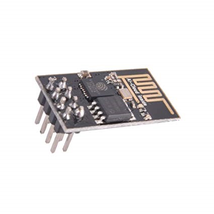
- Wi-Fi Module (ESP8266-01): Enables the IoT functionality by connecting the system to a cloud platform.
- Relay Module: Controls pumps for water and nutrient delivery.
- Water Pump: Circulates the nutrient solution.
- LED Display (optional): Displays sensor readings locally.
- Power Supply: To power the Arduino and sensors.
- Connecting Wires and Breadboard: For wiring up the circuit.
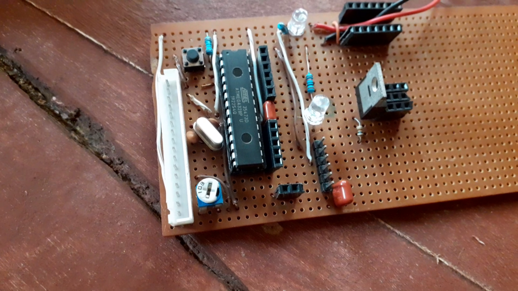
To design and develop the Arduino Uno standalone board, we using the following components mentioned here.
Atmega328P-Pu microcontroller
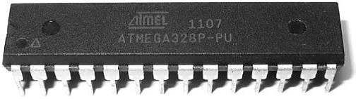
The Atmega328p-pu microcontroller was the type of 28-pin AVR chip used to program, sense, monitor and control the all the sensors used in the construction of this project. It is the brain of the project because it reads the analog sensors with its analog IO pins, sends serials communications and dislays results also on the display modules.
16MHz crystal oscillator
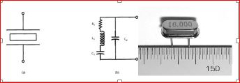
More commonly known as simply a crystal, the crystal oscillator creates an electrical signal with a very accurate frequency. In this case, the frequency is 16 MHz Crystals are not polarized. The schematic symbol is shown in Figure 3.12. The crystal determines the microcontroller’s speed of operation. For example, the microcontroller circuit we’ll be assembling runs at 16 MHz, which means it can execute 16 million processor instructions per second. That doesn’t mean it can execute a line of sketch or a function that rapidly, however, since it takes many processor instructions to interpret a single line of code.
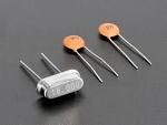
22pF Capacitors
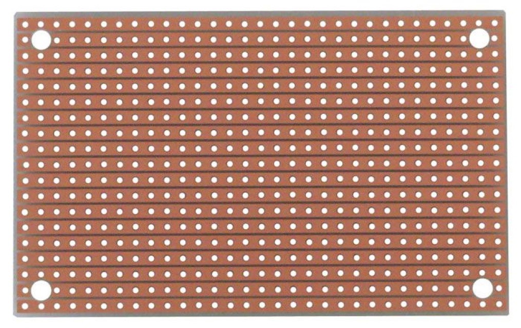
Perforated boards
Dallas temperature sensor DS18B20:
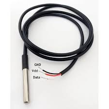
The DS18B20 digital thermometer provides 9-bit to 12-bit Celsius temperature measurements and has an alarm function with nonvolatile user-programmable upper and lower trigger points. The DS18B20 communicates over a 1-Wire bus that, by definition, requires only one data line (and ground) for communication with a central microprocessor. In addition, the DS18B20 can derive power directly from the data line (“parasite power”), eliminating the need for an external power supply. Each DS18B20 has a unique 64-bit serial code, which allows multiple DS18B20s to function on the same 1-Wire bus. Thus, it is simple to use one microprocessor to control many DS18B20s distributed over a large area. Applications that can benefit from this feature include HVAC environmental controls, temperature monitoring systems inside buildings, equipment, or machinery, and process monitoring and control systems.
5V Single Channel Relay Module
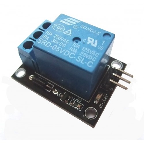
A relay is used to turn on and turn off the power supply that energizes the solenoid valve which pumps water into the hydroponic farm. The relay receives control signals from the microcontroller via an SMD transistor. A diode is used in parallel with the coil pin of relay to avoid sparking in the case of back EMF. because the coil is made of inductive material. The selection of the relay depends on the load of our system. For example, for a maximum load of our home devices, say, 10 amps. Another important thing considered while selecting a relay for this project was the switching speed of the relay. The relay speed was noted to be as fast as possible. Because the faster the switching speed of the relay, the more protection it will provide to the load devices when turning them on or off in the minimum possible time.
pH Sensor
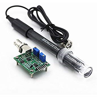
Gravity Analog TDS Sensor
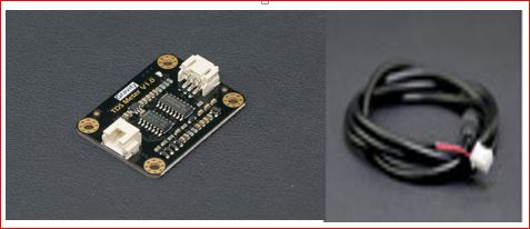
The Total Dissolved Solid sensor was used in place of the Electrical Conductivity (EC) sensor because of its relatively low cost value compared the EC sensor. Also, because there is a conversion scale between the EC sensor and the TDS sensor. This means that we could convert the reading of the TDS from its analog value to the reading in part per million(ppm).This is an AVR microcontroller-compatible TDS sensor/Meter Kit for measuring TDS value of the hydroponic water. Used, in order to reflect the cleanliness of the water; and to conduct our water quality testing for the hydroponic culture.
The module sensor supports 3.3- 5.5V wide range voltage input and 0 to 2.3V analog voltage output which makes it compatible with 5V or 3.3V control system or dev. boards. The excitation source is Ac signal, which can effectively prevent the probe from polarization and prolong the lifetime of the probe. also, increase the output signal stability. The TDS probe is waterproof, it can e immersed in water for a long time for measurement. However, the probe should not be used in water with temperatures above 55 degrees centigrade. Again, the probe touching the container affects the reading of the TDS sensor.
20×4 Liquid Crystal Display (LCD)
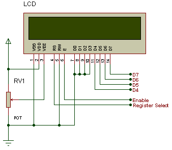
An LCD is an electronic display module which uses liquid crystal to produce a visible image. The 20×4 LCD display is a very basic module commonly used in DIYs and circuits. It was used in a 4-bit configuration interfacing with the MCU. The 20×4 translates on a display 20 characters per line in 4 of such lines. In this LCD, each character is displayed in a 5×7-pixel matrix. This is the visual output where all the commands made and decisions taken by the ‘brain’, the microcontroller unit (MCU) are displayed. It has 16 special pins that are mapped out for special functions.
The ESP-01 Wi-Fi Module
Relative Humidity and Temperature Sensor (DHT11)
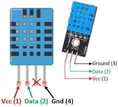
The DHT11 is a low cost digital humidity and temperature (DHT). This sensor is very basic and slow, but is great for some basic data logging. The DHT11 sensor is made of two parts, a capacitive humidity sensor and a thermistor. There is also a very basic chip inside that does some analog to digital conversion and spits out a digital signal with the temperature and humidity. The digital signal is fairly easy to read using any microcontroller.
THE CIRCUIT DIAGRAM FOR THE DESIGN
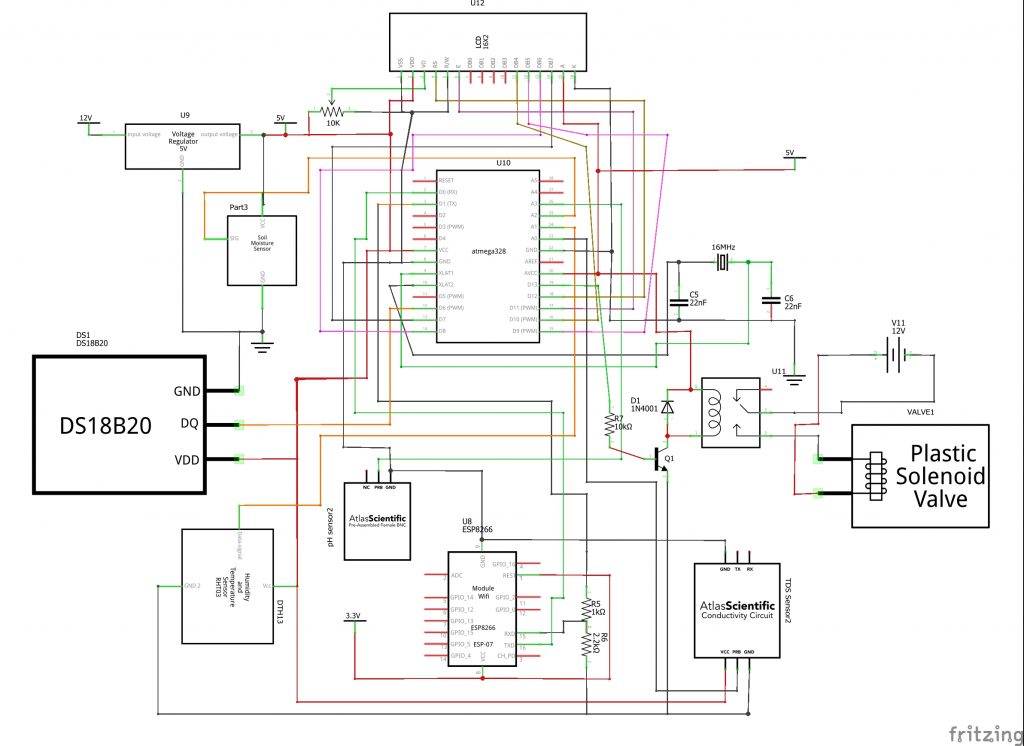
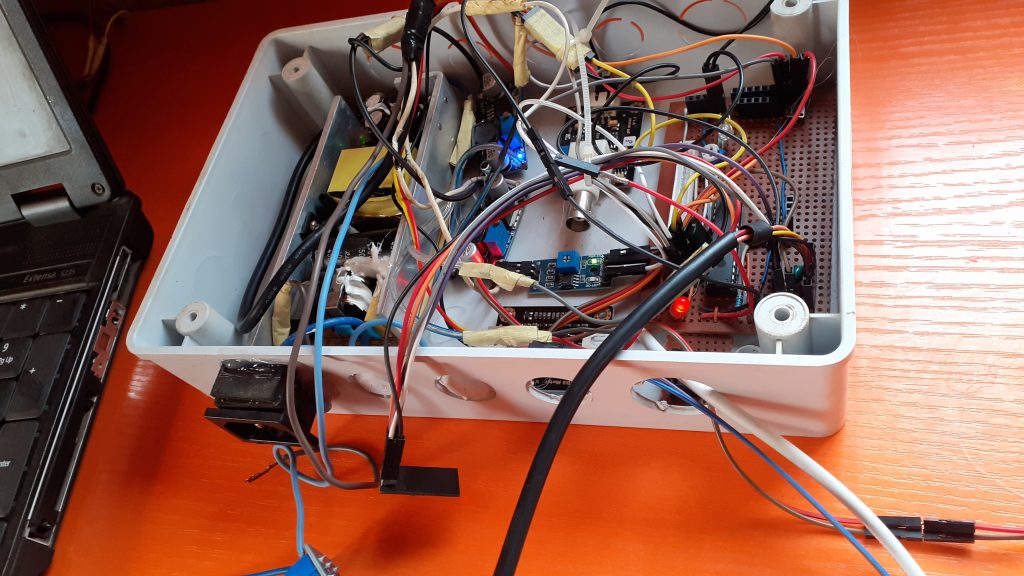
Construction of the Circuit Diagram
Arduino Source Code
PROGRAMMING THE DESIGN
#include <SoftwareSerial.h>
SoftwareSerial EspSerial(2, 3);

String statusChWriteKey = "xxxxxxxxxxxxxxxxx";
#define HARDWARE_RESET 4

long writeTimingSeconds = 17;
long startWriteTiming = 0;
long elapsedWriteTime = 0;

#include <DallasTemperature.h>
#include <OneWire.h>
#include "DHT.h"
// include the library code:
#include <LiquidCrystal.h>

#define ONE_WIRE_BUS 6
#define DHTPIN A0
OneWire oneWire(ONE_WIRE_BUS);
DallasTemperature sensors(&oneWire);

boolean error;

#define SensorPin A3            //pH meter Analog output to Arduino Analog Input 0
#define Offset 0.00            //deviation compensate
#define DHTTYPE DHT11   // DHT 11
#define LED 13


LiquidCrystal lcd(12, 11, 10, 9, 8, 7);


#define TdsSensorPin A1
#define VREF 5.0      // analog reference voltage(Volt) of the ADC
#define SCOUNT  30           // sum of sample point
int analogBuffer[SCOUNT];    // store the analog value in the array, read from ADC
int analogBufferTemp[SCOUNT];
int analogBufferIndex = 0,copyIndex = 0;
float averageVoltage = 0,tdsValue = 0,temperature = 25;

DHT dht(DHTPIN, DHTTYPE);
#define samplingInterval 20
#define printInterval 800
#define ArrayLenth  40    //times of collection
int pHArray[ArrayLenth];   //Store the average value of the sensor feedback
int pHArrayIndex=0;

 float Celcius=0;
 float Fahrenheit=0;
 float h,t,f;
 static float pHValue,voltage;
 float newPH;

int pumpStatus;
int waterSense;
int alarmSense;

void setup(void)
{
  EspSerial.begin(9600);
  Serial.begin(9600);
  Serial.begin(115200);
  pinMode(HARDWARE_RESET, OUTPUT);
  digitalWrite(HARDWARE_RESET, HIGH);
  EspHardwareReset();
  startWriteTiming = millis();
  pinMode(LED,OUTPUT);
  pinMode(TdsSensorPin,INPUT);
  pinMode(A5, OUTPUT);
  pinMode(A4, OUTPUT);

  analogWrite(A4, 255);
  analogWrite(A5, 0);

     sensors.begin();
  Serial.println("pH meter experiment!");    //Test the serial monitor
   Serial.println(F("DHTxx test!"));
dht.begin();
//begin the lcd sensor
   sensors.begin();
   lcd.begin(20, 4);
   lcd.setCursor(0, 0);
   lcd.print("   WELCOME JALANI");
   lcd.setCursor(0, 1);
   lcd.print("  SMART HYDROPONIC");
   lcd.setCursor(0, 2);
   lcd.print(" INTERNET OF THINGS");
   lcd.setCursor(0, 3);
   lcd.print("      PROJECT");
        delay(3000);
   lcd.clear();

   lcd.setCursor(0, 0);
   lcd.print("       PLS ");
   lcd.setCursor(0, 1);
   lcd.print("     GIVE TIME ");
   lcd.setCursor(0, 2);
   lcd.print("  FOR THE SENSORS ");
   lcd.setCursor(0, 3);
   lcd.print("     TO BOOTH ");
   delay(2000);
   lcd.clear();

 lcd.setCursor(1, 0);
 lcd.print("TEMP");
 lcd.setCursor(9, 0);
 lcd.print("TDS");
 lcd.setCursor(18, 0);
 lcd.print("pH");

 lcd.setCursor(0, 2);
 lcd.print("W.LEVEL");
 lcd.setCursor(9, 2);
 lcd.print("HUM");
 lcd.setCursor(14, 2);
 lcd.print("A.TEMP");

}


void waterLevel(){
  waterSense= analogRead(A2);
  Serial.println(waterSense);
  //print out on LCD
 lcd.setCursor(0, 3);
 lcd.print(waterSense);
 //lcd.setCursor(3, 3);
 //lcd.print("cm");
  delay(500);

   if(waterSense > 500){
    analogWrite(A4, 0);
   }

   if(waterSense <= 240){
    analogWrite(A4, 255);
   }

}

void humSensor(){
  // Wait a few seconds between measurements.
  delay(2000);

  // Reading temperature or humidity takes about 250 milliseconds!
  // Sensor readings may also be up to 2 seconds 'old' (its a very slow sensor)
  h = dht.readHumidity();
  // Read temperature as Celsius (the default)
  t = dht.readTemperature();
  // Read temperature as Fahrenheit (isFahrenheit = true)
   f = dht.readTemperature(true);

  // Check if any reads failed and exit early (to try again).
  if (isnan(h) || isnan(t) || isnan(f)) {
    Serial.println(F("Failed to read from DHT sensor!"));
    return;
  }

  // Compute heat index in Fahrenheit (the default)
  float hif = dht.computeHeatIndex(f, h);
  // Compute heat index in Celsius (isFahreheit = false)
  float hic = dht.computeHeatIndex(t, h, false);

  lcd.setCursor(8, 3);
  lcd.print(h);
  lcd.setCursor(15, 3);
  lcd.print(t);

  if(h <= 10.00){
    analogWrite(A5, 255);
    lcd.clear();
    lcd.setCursor(0, 0);
    lcd.print("AIR TOO DRY");
  }
  else {

  }

  Serial.print(F("Humidity: "));
  Serial.print(h);
  Serial.print(F("%  Temperature: "));
  Serial.print(t);
  Serial.print(F("°C "));
  Serial.print(f);
  Serial.print(F("°F  Heat index: "));
  Serial.print(hic);
  Serial.print(F("°C "));
  Serial.print(hif);
  Serial.println(F("°F"));
}

void pH(){
  static unsigned long samplingTime = millis();
  static unsigned long printTime = millis();
  if(millis()-samplingTime > samplingInterval)
  {
      pHArray[pHArrayIndex++]=analogRead(SensorPin);
      if(pHArrayIndex==ArrayLenth)pHArrayIndex=0;
      voltage = avergearray(pHArray, ArrayLenth)*5.0/1024;
      pHValue = 3.5*voltage+Offset;
      samplingTime=millis();
  }
  if(millis() - printTime > printInterval)   //Every 800 milliseconds, print a numerical, convert the state of the LED indicator
  {
    Serial.print("Voltage:");
        Serial.print(voltage,2);
                newPH = pHValue + 5.60;
        newPH = map(newPH, 0.00, 14.00, 1.00, 14.00);
        Serial.print("    pH value: ");
    Serial.println(newPH,2);

    lcd.setCursor(17, 1);
 lcd.print(newPH);

    digitalWrite(LED,digitalRead(LED)^1);
    printTime=millis();
  }
}
double avergearray(int* arr, int number){
  int i;
  int max,min;
  double avg;
  long amount=0;
  if(number<=0){
    Serial.println("Error number for the array to avraging!/n");
    return 0;
  }
  if(number<5){   //less than 5, calculated directly statistics
    for(i=0;i<number;i++){
      amount+=arr[i];
    }
    avg = amount/number;
    return avg;
  }else{
    if(arr[0]<arr[1]){
      min = arr[0];max=arr[1];
    }
    else{
      min=arr[1];max=arr[0];
    }
    for(i=2;i<number;i++){
      if(arr[i]<min){
        amount+=min;        //arr<min
        min=arr[i];
      }else {
        if(arr[i]>max){
          amount+=max;    //arr>max
          max=arr[i];
        }else{
          amount+=arr[i]; //min<=arr<=max
        }
      }//if
    }//for
    avg = (double)amount/(number-2);
  }//if
  return avg;
}


void TDS(){
  static unsigned long analogSampleTimepoint = millis();
   if(millis()-analogSampleTimepoint > 40U)     //every 40 milliseconds,read the analog value from the ADC
   {
     analogSampleTimepoint = millis();
     analogBuffer[analogBufferIndex] = analogRead(TdsSensorPin);    //read the analog value and store into the buffer
     analogBufferIndex++;
     if(analogBufferIndex == SCOUNT)
         analogBufferIndex = 0;
   }
   static unsigned long printTimepoint = millis();
   if(millis()-printTimepoint > 800U)
   {
      printTimepoint = millis();
      for(copyIndex=0;copyIndex<SCOUNT;copyIndex++)
        analogBufferTemp[copyIndex]= analogBuffer[copyIndex];
      averageVoltage = getMedianNum(analogBufferTemp,SCOUNT) * (float)VREF / 1024.0; // read the analog value more stable by the median filtering algorithm, and convert to voltage value
      float compensationCoefficient=1.0+0.02*(temperature-25.0);    //temperature compensation formula: fFinalResult(25^C) = fFinalResult(current)/(1.0+0.02*(fTP-25.0));
      float compensationVolatge=averageVoltage/compensationCoefficient;  //temperature compensation
      tdsValue=(133.42*compensationVolatge*compensationVolatge*compensationVolatge - 255.86*compensationVolatge*compensationVolatge + 857.39*compensationVolatge)*0.5; //convert voltage value to tds value
      //Serial.print("voltage:");
      //Serial.print(averageVoltage,2);
      //Serial.print("V   ");
      Serial.print("TDS Value:");
      Serial.print(tdsValue,0);
      Serial.println("ppm");

      lcd.setCursor(8, 1);
 lcd.print(tdsValue);
 lcd.setCursor(13, 1);
 lcd.print("ppm");
   }
}
int getMedianNum(int bArray[], int iFilterLen)
{
      int bTab[iFilterLen];
      for (byte i = 0; i<iFilterLen; i++)
      bTab[i] = bArray[i];
      int i, j, bTemp;
      for (j = 0; j < iFilterLen - 1; j++)
      {
      for (i = 0; i < iFilterLen - j - 1; i++)
          {
        if (bTab[i] > bTab[i + 1])
            {
        bTemp = bTab[i];
            bTab[i] = bTab[i + 1];
        bTab[i + 1] = bTemp;
         }
      }
      }
      if ((iFilterLen & 1) > 0)
    bTemp = bTab[(iFilterLen - 1) / 2];
      else
    bTemp = (bTab[iFilterLen / 2] + bTab[iFilterLen / 2 - 1]) / 2;
      return bTemp;
}

void loop(void)
{
  sensors.requestTemperatures();
  Celcius=sensors.getTempCByIndex(0);
  Fahrenheit=sensors.toFahrenheit(Celcius);
   Serial.print(Celcius);
    Serial.print(" 'C  ");

   if(Celcius >= 85.00){
    analogWrite(alarmSense, 255);
    lcd.clear();
    lcd.setCursor(0, 0);
    lcd.print("TEMP TO HIGH!");
   }
   else{

   }
     lcd.setCursor(0, 1);
 lcd.print(Celcius);
 lcd.setCursor(5, 1);
 lcd.print("'C");
 Serial.println(Celcius);
 delay(500);

  waterLevel();
   pH();
 humSensor();
  TDS();

int pumpStatus = analogRead(A4);
int alarmSense = analogRead(A5);

  //start: //label
  //error=0;

  elapsedWriteTime = millis()-startWriteTiming;

  if (elapsedWriteTime > (writeTimingSeconds*1000))
  {
       writeThingSpeak();
    startWriteTiming = millis();
  }

  if (error==1) //Resend if transmission is not completed
  {
    Serial.println(" <<<< ERROR >>>>");
    delay (2000);
    //goto start; //go to label "start"
  }
 }

 void writeThingSpeak(void)
{
  startThingSpeakCmd();
  // preparacao da string GET
  String getStr = "GET /update?api_key=";
  getStr += statusChWriteKey;
  getStr +="&field1=";
  getStr += String(t);
 getStr +="&field2=";
  getStr += String(h);
   getStr +="&field3=";
  getStr += String(Celcius);
  getStr +="&field4=";
  getStr += String(newPH);
  getStr +="&field5=";
  getStr += String(tdsValue);
  getStr +="&field6=";
  getStr += String(waterSense);
  getStr +="&field7=";
  //getStr += String(pumpStatus);
  getStr +="&field8=";
  //getStr += String(alarmSense);
  getStr += "\r\n\r\n";
  sendThingSpeakGetCmd(getStr);
}

void EspHardwareReset(void)
{
  Serial.println("Reseting.......");
  digitalWrite(HARDWARE_RESET, LOW);
  delay(500);
  digitalWrite(HARDWARE_RESET, HIGH);
  delay(8000);//Tempo necessário para começar a ler
  Serial.println("RESET");
}
/********* Start communication with ThingSpeak*************/
void startThingSpeakCmd(void)
{
  EspSerial.flush();//limpa o buffer antes de começar a gravar

  String cmd = "AT+CIPSTART=\"TCP\",\"";
  cmd += "184.106.153.149"; // Endereco IP de api.thingspeak.com
  cmd += "\",80";
  EspSerial.println(cmd);
  Serial.print("enviado ==> Start cmd: ");
  Serial.println(cmd);
  if(EspSerial.find("Error"))
  {
    Serial.println("AT+CIPSTART error");
    return;
  }
}
/********* send a GET cmd to ThingSpeak *************/
String sendThingSpeakGetCmd(String getStr)
{
  String cmd = "AT+CIPSEND=";
  cmd += String(getStr.length());
  EspSerial.println(cmd);
  Serial.print("enviado ==> lenght cmd: ");
  Serial.println(cmd);
  if(EspSerial.find((char *)">"))
  {
    EspSerial.print(getStr);
    Serial.print("enviado ==> getStr: ");
    Serial.println(getStr);
    delay(500);//tempo para processar o GET, sem este delay apresenta busy no próximo comando
    String messageBody = "";
    while (EspSerial.available())
    {
      String line = EspSerial.readStringUntil('\n');
      if (line.length() == 1)
      { //actual content starts after empty line (that has length 1)
        messageBody = EspSerial.readStringUntil('\n');
      }
    }
    Serial.print("MessageBody received: ");
    Serial.println(messageBody);
    return messageBody;
  }
  else
  {
    EspSerial.println("AT+CIPCLOSE");     // alert user
    Serial.println("ESP8266 CIPSEND ERROR: RESENDING"); //Resend...
    //spare = spare + 1;
    error=1;
    return "error";
  }
}
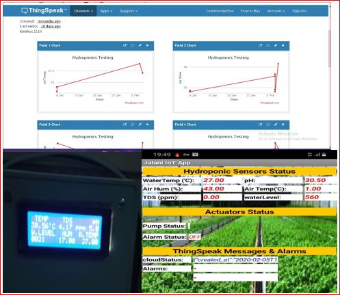
The IoT Dashboard
The above sketch is to be uploaded into the standalone board using the Arduino IDE and then the next step is to configure Thingspeak DB and create an app using MIT AppInventor.
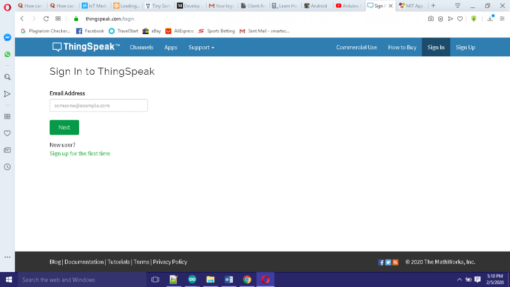
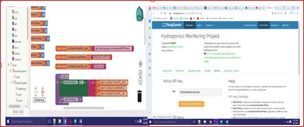
To use thingspeak database, we need to create a Matlab account. Simply sign up on their website; www.thingspeak.com. After signing up, verify your email and sign in.
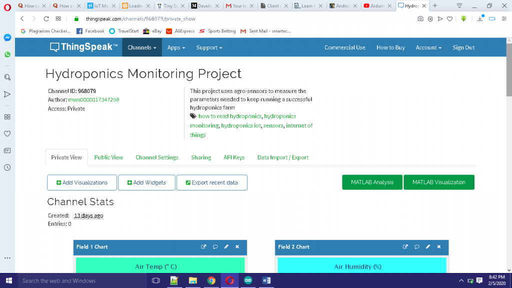
Once signed in, create a channel. Name your channel. Copy and safely store the API Write Key and the API Read Key. You can allocate your channel to any number of fields or charts. For us, we used 8 fields: 6 for sensors and 2 for actuators.
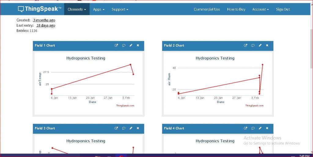
After changing the API Write Key in your sketch, upload the code to see this working on the thingspeak channel you made.
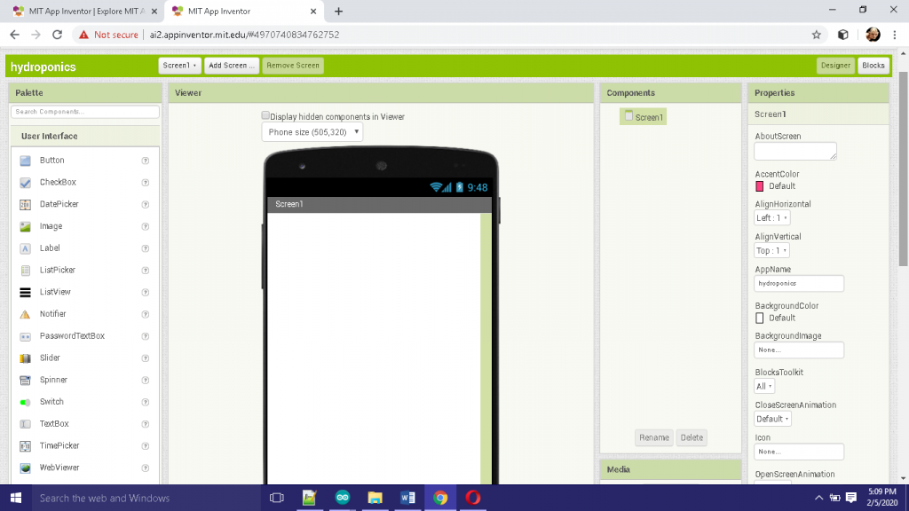
Creating the Hydroponics IoT Project Mobile App
Next go to MIT app inventor website to create your app. After signing in, you can just import our already made .aia file into your project. You can edit any part of it to your taste. Just make sure to change the API write key to your own.
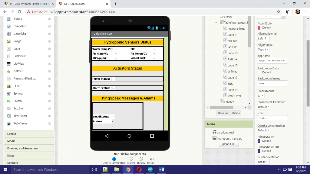
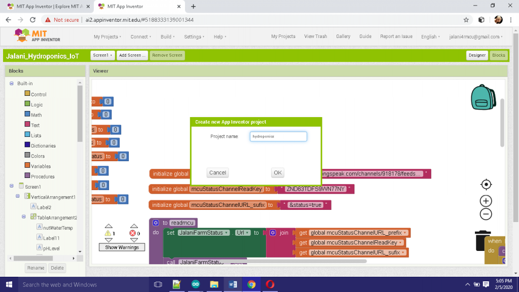
once the app is done, you could either use the emulator to test it or you build and copy to your android phone for installation. After running the app, you can compare the reading with those updating on thingspeak DB.
Now the sensor and actuator states can be viewed anywhere around the globe using a web app or a mobile app.
But also the actuators, the Solenoid pump is meant to automatically pump water into the base bucket when the water level is too low and the alarm is meant to go off when the temperature is too high. The threshold for this state can be adjusted in the sketch above.
🌿Applications & Use Cases
This smart hydroponics project can be scaled and adapted for various applications:
- Urban Farming: With space limitations in cities, this system can help grow plants in small spaces with minimal manual intervention.
- Research: Scientists can use the system to study the effect of different environmental parameters on plant growth.
- Commercial Agriculture: Large-scale hydroponic farms can benefit from the automation and remote monitoring provided by this project.
- Home Gardens: For hobbyists, it’s a great way to grow vegetables or herbs at home without needing constant supervision.
A visual tutorial is given in the YouTube video below.
Benefits of IoT-Based Smart Hydroponics
Using IoT to automate a hydroponic system offers several key advantages:
- Real-time Monitoring: You can keep track of your plants’ health from anywhere, ensuring optimal growing conditions.
- Automation: The system automatically takes care of watering and nutrient delivery, reducing the need for manual intervention.
- Data-Driven Decisions: By analyzing historical data, you can adjust environmental parameters for better plant growth.
- Water Efficiency: Hydroponic systems are already water-efficient, and IoT adds another layer of control to minimize water waste.
Conclusion
You may use technology to promote sustainable farming by developing a Smart Hydroponics IoT Project. You can automate critical tasks like temperature, pH, and water level monitoring while also enabling remote access and control by utilizing Arduino and the Internet of Things. In addition to saving time, this project helps guarantee that your plants have the optimum growing conditions.
A smart hydroponics system is a great way to embrace the future of farming, whether you’re an urban farmer, a researcher, or a gardening lover. So why hold off? Utilize the potential of IoT to take charge of your garden by starting to create your system today.
Now we have shown you how we achieved this project, smart infrared remote control gate system. Kindly let us know if you were able to build such similar project or a better version. We will be very glad to help you the best we we can. Let us know if you have any further questions in the comment section. You can also drop a suggestion too! To join the conversation, join our Telegram community, Telegram, Facebook page, Instagram and Twitter.
Read More
FAQs on Hydroponics IoT Project
What is the role of the pH sensor in a hydroponics system? The pH sensor monitors the acidity or alkalinity of the nutrient solution. Maintaining the correct pH is crucial for optimal plant growth, as it affects nutrient absorption.
Can I use a different Wi-Fi module instead of ESP8266 or ESP32? Yes, you can use other Wi-Fi modules like the ESP01 or NodeMCU, but ESP8266 and ESP32 are preferred due to their reliability and community support.
Is this system scalable for commercial farming? Absolutely! This system can be scaled by adding more sensors, pumps, and relays. You can also expand the IoT features for more detailed data analysis and control.
How do I ensure the sensors stay accurate over time? Regularly calibrating the sensors, especially the pH sensor, is essential. Over time, sensors can degrade, so it’s also important to replace them when necessary.
Can this system work offline if there’s no internet connection? While the IoT features rely on an internet connection, the core system (sensor readings and relay controls) will continue to function offline, ensuring that plant care isn’t interrupted.

