This project design is an IoT (Internet of Things), smart home automation and surveillance project that was based on using Telegram and Blynk servers to host home automation controls and surveillance procedures. The project is designed and programmed around a two-bedroom flat model home. The entrance has a motion triggered visitor camera made from the famously low cost ESP32 cam. Each of the bedrooms, including the sitting room, lightings and load points are controlled remotely via an IoT Blynk dashboard. The system is programmed to to alert the owner of the home of any visitor at the entrance door through a telegram alert. The project design is meant to work as follows, in summary:
- Use the motion sensor to trigger a telegram alert that is sent to your phone any time a visitor is at the entrance door.
- The owner can put out his/her phone on such notification and open the Blynk, from where
- Controls the home appliances through the Blynk app dashboard and from there, take another view of the visitor, if it is someone he/she wants to come inside his house, he can open the door, for the person remotely.
- Captures an image of picture of the visitor at the entrance door and displays it on the image widget on telegram and send a backup copy to the telegram app channel.
- The system also allow for auto opening of the doors to each rooms form the Blynk app driectly.
- The speed control for ventilations from all of the fans in the room are controlled on the Blynk app.
- All load points that is AC sockets are controlled remotely too from the app.
Introduction
Home automation refers to the use of technology to control and automate various aspects of a home, such as lighting, heating, and appliances. This can be done through the use of smart devices, such as smartphones or tablets, which can be used to remotely control and monitor these systems. Home automation systems can also be integrated with other smart devices, such as voice assistants, to provide a more seamless and convenient user experience.
Home surveillance, on the other hand, refers to the use of technology to monitor and secure a home. This can be done through the use of cameras and other sensors, which can be used to detect and deter intruders, as well as to monitor the comings and goings of people and pets. Some home surveillance systems also include features such as motion detection and facial recognition, which can be used to alert homeowners of potential threats and to automatically trigger an alarm.
When combined, home automation and surveillance can provide a powerful and comprehensive solution for securing and managing a home. Smart cameras, for instance, can be integrated with home automation systems to allow homeowners to monitor their home remotely and to control lighting and appliances in response to motion detection. Similarly, home automation systems can be integrated with surveillance systems to automatically trigger an alarm when an intrusion is detected.
Components Needed For this Project
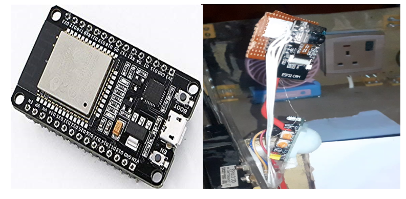
- ESP32 Dev board……………………………..Buy here
- ESP32 Cam board……………………………..Buy here
- 5V solid state relay…………………………….Buy here
- 10K resistor……………………………..Buy here
- TIP421C Transistor……………………………..Buy here
- Miscellaneous part, please contact us.
The Circuit Diagram
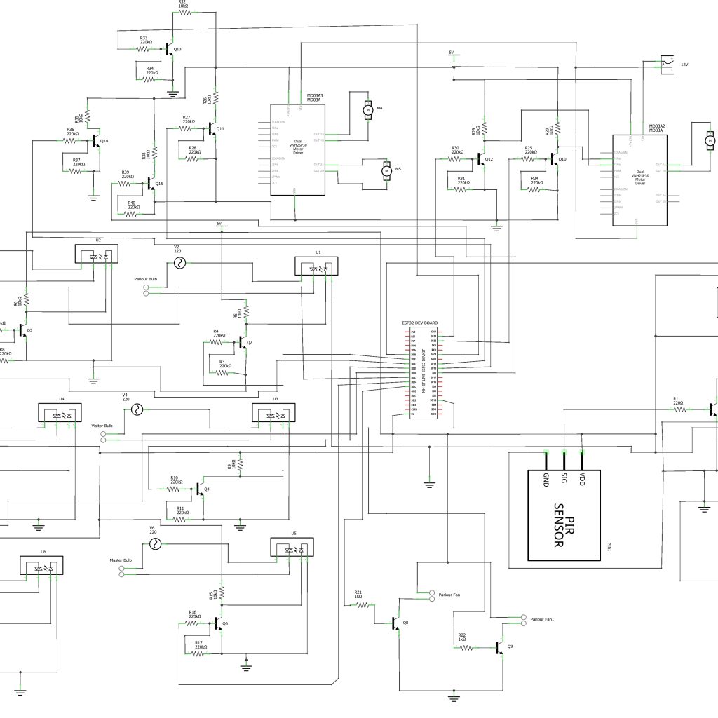
The Circuit Diagram Explanation
The circuit diagram is divided into two parts, namely; the IoT home automation part that is built around the famous ESP32 development board. And the IoT surveillance system part that is built around the ESP32 Cam development board. The system is powered by a 12V power supply to run the three Direct Current (DC) motors that are connected to to the motor driver module L293. Since the ESP32 development board works on 5V, a DC-DC buck converter was needed to step this 12V to 5V.
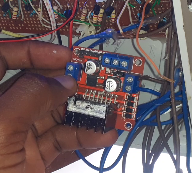
The two DC motor driver modules are powered by the 12V power supply, motor driver module one was used to drive two model doors used for the rooms other than the sitting room. The other motor driver was used to control the movement of the door leading to the sitting room. The directional movement of these DC motors would cause opening and closing effects on the doors, making them sliding doors that can be controlled remotely via an app.
The first motor driver module was connected 4 input pins to control the two DC motors (model doors). This is shown in the circuit diagram above. These input pins come from the ESP32 dev board. Whereas the second motor driver module as only 2 input connection to the ESp32 dev board. This is because it only controls one model door which is the entrance door to the sitting room.
The circuit diagram shows that a logic inverter was made from a simple transistor circuit that allowed the motor driver to receive 5V HIGH and 0V LOW from the ESP32 Dev board rather than the usual 3.3V and 0V logic level.
The Actuators
These are mainly made of solid state relay modules designed with logic inverters that would help switch the states of the AC light bulbs and the load point AC sockets. The relay module was custom built by us to be a 6-channel relay module that controls the 3 load point sockets and the the 3 lightening bulbs in the rooms.
Since the solid state relay works on 5V logic, the ESP32 dev board can only output 3.3V logic. We also used the logic inverter/amplifier to convert this to 5V. This also meant however that, when the ESP32 dev board sends an output of 3.3V, the inverter inverts this to give 0V. Whereas when the ESP32 dev board sends a logic output, the inverter converts this to 5V high.
The AC actuators are wired to in such a way that the neutral are connected together while the Live (L) wires are connected through the solid state relay. This is shown in the circuit diagram shown above. The solid state relay is energized when the user presses the button on the app or sends a command through the Telegram app.
The Surveillance System
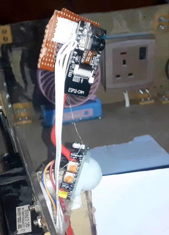
This part of the project was made with the ESP32 Cam and the PIR motion sensor. The ESP32 Cam was connected to the output signal pin of the PIR sensor so that once it senses the presence of a person, it can trigger the ESP32 Cam to take a picture. Once this picture is taken, it is sent to the Telegram as a cloud based backup and also a copy is sent to the Blynk image widget.
Designing The Control Blynk App
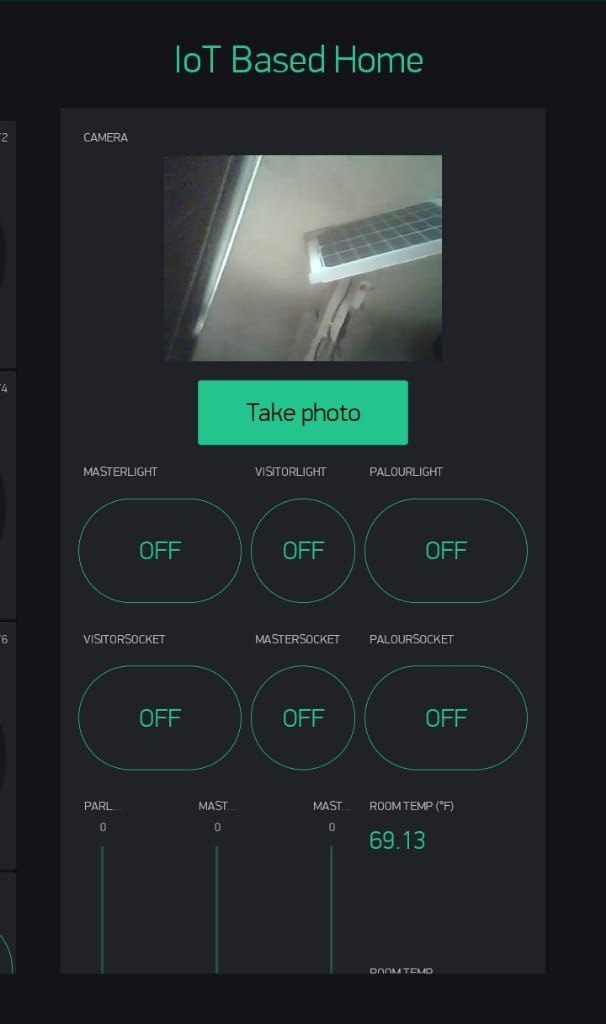
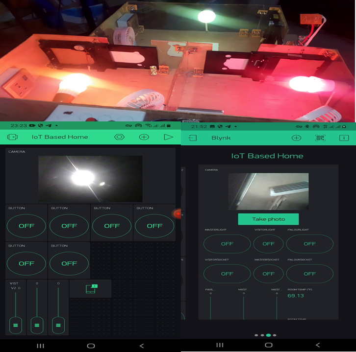
This project used the Blynk legacy app but if you want to use the latest version of Blynk, contact us here. See this blog post on how to create an app on the Blynk platform. The design here used the image widget where the images taken when the “take photo” button is pressed. It displays the picture taken by the ESP32 Cam on this app. Thereby letting the user know who is at the entrance door.
The app design has six (6) control pushbuttons for the home appliances connected in the model house. The first upper three pushbuttons were used to control the lightnings in the rooms. While the lower 3 pushbuttons were used to control the loadpoint sockets.
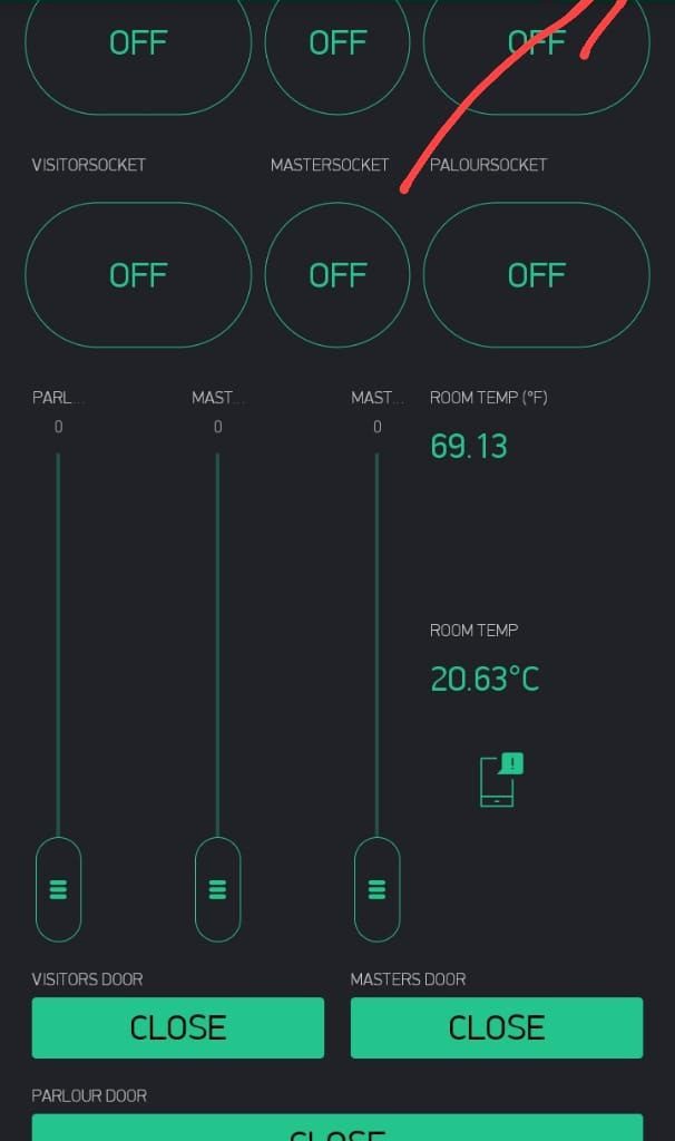
Three (3) slider widgets were used to control the speed of the fans that are place in the room. The slier widgets keeps the fan speeds at maximum when the slider buttons are place at the very vertical tops. Whereas when they are moved down to the bottom, it reduces the fans’ speeds until they come to a stop.
To control the direction of the doors in the rooms, three other pushbuttons were added. These pushbuttons are placed horizontally and are much larger in side than previous one. These pushbuttons were labelled “OPEN ” and “CLOSE”. When the door is closed, the pushbutton widget would display, Open. and it is opened, the pushbutton widget would display Close.
The app design also has an app notifier and a room temperature display widget that can display the room temperature in the house. This is shown in the picture above as the temperature is both displayed in both Celsius and Fahrenheit degrees.
The Telegram Bot App
The project design used the Telegram bot to alert the user of any visitor at the entrance door and also to save the captured picture of such visitor with timestamp as backup. To create this Telegram bot is quite easy.
For the project to have authorized user access, a telegram bot was created to have the choice of arming and disarming the project design. To do this we had to create a bot using botFather.
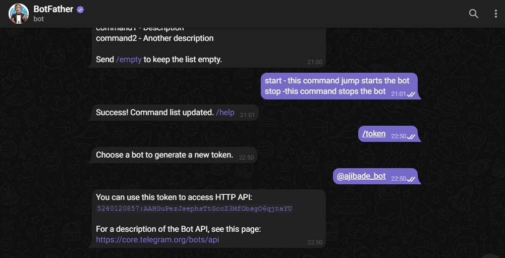
The Botfather is a chat bot that allowed us to create our own custom bot. The bot father had commands that would start it and end the chat with users. When it is sent “/start”, it returns some options from which new commands can be sent. This allowed us to get the API key when we put in the program we uploaded into the ESP32 Cam and ESP32. With this API key, we can assign admin role to users who have access to this bot. such that they can send commands to it and receive feedbacks remotely.
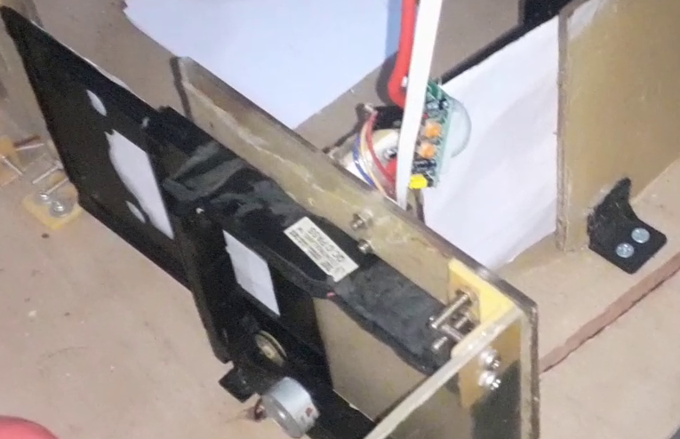
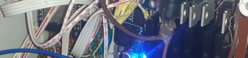
Modelling the Project Design
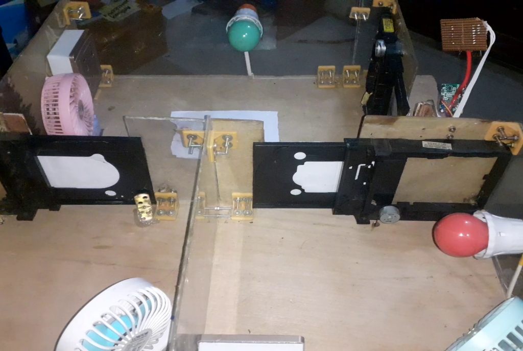
The IoT home automation and surveillance system was constructed on a stripboard by assembling the components accordingly before soldering with solder and soldering iron. The 3D model was done on a flat board with dimensions measured out accordingly as shown in the picture above.
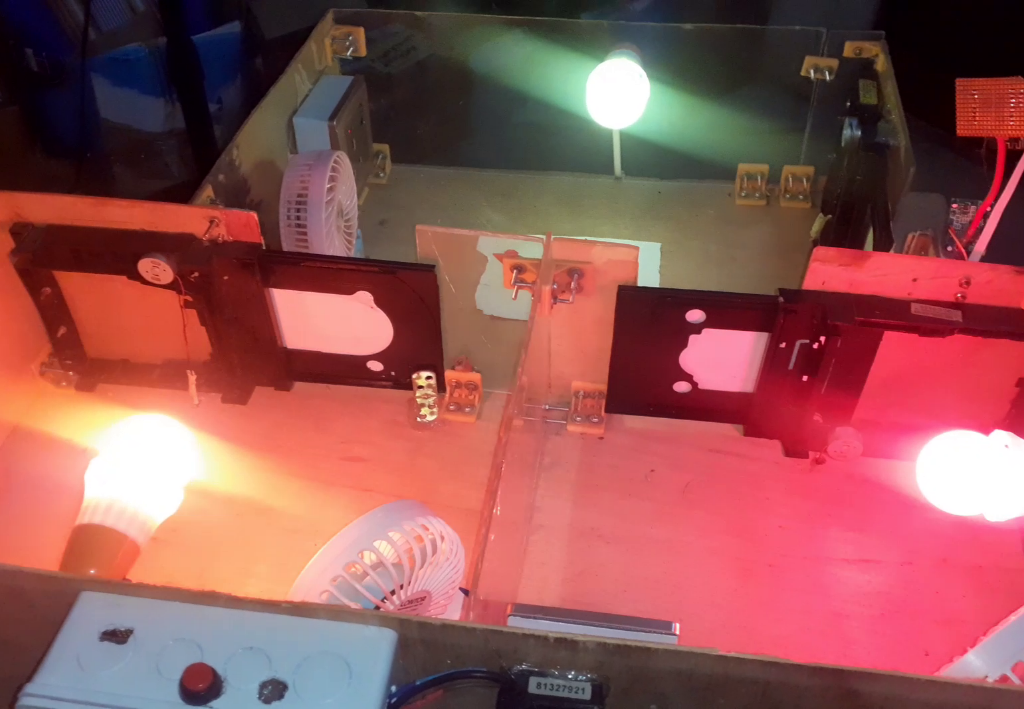
The demo modelling was done on a plywood board. For the demonstration of this project, a plywood of thickness 0.5” (inches) with dimension 40cm by 28.5cm ; was cut out, its surface further smoothened.
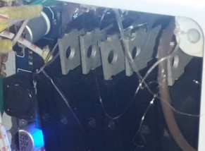
Casing the Control Box
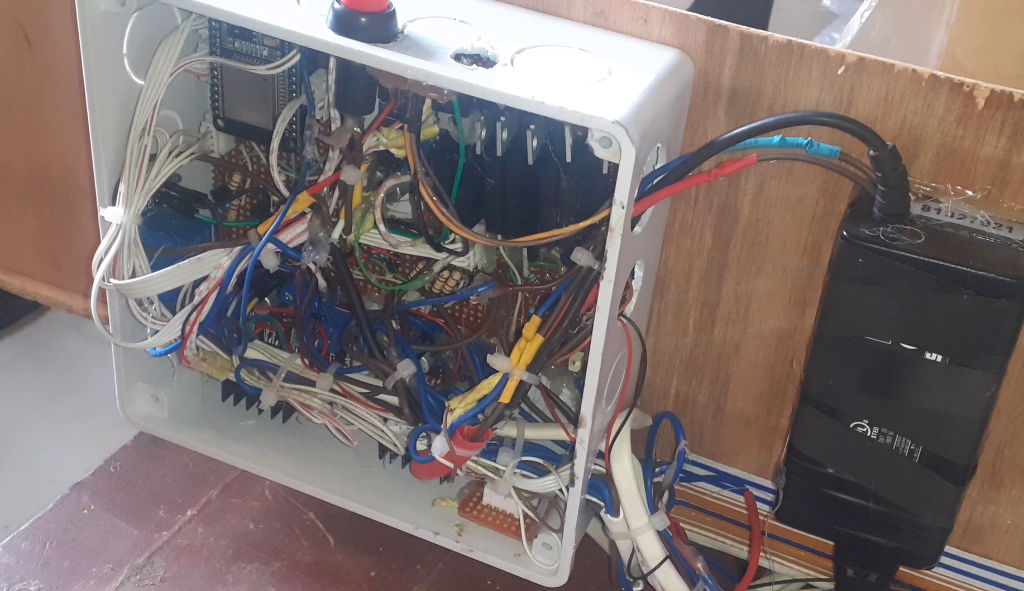
The casing was made to be a house model shown in the figure 3.25 below. The casing encased the most of the components and modules use in the project design. It was made from a (6×6)” pattress box. The power supply adaptor was screwed to the side so as to get easy access to DC power supply into the box.
The Arduino Source Code
The Arduino source code for this project design is into parts namely, the Arduino source for the ESP32 Dev board and the Arduino source code for the ESP32 Cam board.
Arduino Source Code for ESP32 Dev Board
#include <Arduino.h>
#include <analogWrite.h>
#define BLYNK_PRINT Serial
#include <WiFi.h>
#include <WiFiClient.h>
#include <BlynkSimpleEsp32.h>


#define ADC_VREF_mV    3300.0 // in millivolt
#define ADC_RESOLUTION 4096.0
#define PIN_LM35       34

#define visitorLight 33
#define masterLight 32
#define visitorSocket 18
#define parlourLight 5
#define masterSocket 19
#define parlourSocket 21

#define parlourDoorLeft 14
#define parlourDoorRight 27
#define visitorDoorLeft 26
#define visitorDoorRight 25
#define masterDoorLeft 13
#define masterDoorRight 12

const int ledPin = 2;
const int ledPin1 = 23;
const int ledPin2 = 15;

int fanWidget,fanWidget2, fanWidget3, visitorLightWidget, masterLightWidget, parlourLightWidget, visitorSocketWidget, masterSocketWidget, parlourSocketWidget;
int visitorDoorWidget, masterDoorWidget, parlourDoorWidget;

#define Authorization_key "a6SdaWEnnAoXTmrYhX_GPvQ8hq_fDEvw" //EExmWR-3B8jC7H0ttOzr9qmtAciGW8DR
#define SSID "AncII"       // replace with your SSID
#define Password "eureka26"           //replace with your password


void openMaster(){
  digitalWrite(masterDoorLeft, LOW);
  digitalWrite(masterDoorRight, HIGH);
}


void closeMaster(){
  digitalWrite(masterDoorLeft, HIGH);
  digitalWrite(masterDoorRight, LOW);
}


void closeParlour(){
  digitalWrite(parlourDoorLeft, HIGH);
  digitalWrite(parlourDoorRight, LOW);
}

void openParlour(){
  digitalWrite(parlourDoorLeft, LOW);
  digitalWrite(parlourDoorRight, HIGH);
}


void openVisitor(){
  digitalWrite(visitorDoorLeft, LOW);
  digitalWrite(visitorDoorRight, HIGH);
}


void closeVisitor(){
  digitalWrite(visitorDoorLeft, HIGH);
  digitalWrite(visitorDoorRight, LOW);
}


BLYNK_WRITE(V0) {
visitorLightWidget = param.asInt();

if(visitorLightWidget == 1){
  digitalWrite(visitorLight, HIGH);
  Serial.println("Visitor's Light ON");
}

else{
  digitalWrite(visitorLight, LOW);
  Serial.println("Visitor Light OFF");
}

}


BLYNK_WRITE(V3) {
masterLightWidget = param.asInt();
 Serial.println(masterLightWidget);

if(masterLightWidget == 1){
  digitalWrite(masterLight, HIGH);
  Serial.println("master's Light ON");
}

else{
  digitalWrite(masterLight, LOW);
  Serial.println("master Light OFF");
}
}


BLYNK_WRITE(V4) {
parlourLightWidget = param.asInt();

if(parlourLightWidget == 1){
  digitalWrite(parlourLight, HIGH);
  Serial.println("parlour Light ON");
}

else{
  digitalWrite(parlourLight, LOW);
  Serial.println("parlour Light OFF");
}
}


BLYNK_WRITE(V16) {
visitorSocketWidget = param.asInt();

if(visitorSocketWidget == 1){
  digitalWrite(visitorSocket, HIGH);
  Serial.println("visitor Socket ON");
}

else{
  digitalWrite(visitorSocket, LOW);
  Serial.println("visitor socket OFF");
}
}


BLYNK_WRITE(V6) {
masterSocketWidget = param.asInt();

if(masterSocketWidget == 1){
  digitalWrite(masterSocket, HIGH);
  Serial.println("master Socket ON");
}

else{
  digitalWrite(masterSocket, LOW);
  Serial.println("master socket OFF");
}
}


BLYNK_WRITE(V7) {
parlourSocketWidget = param.asInt();

if(parlourSocketWidget == 1){
  digitalWrite(parlourSocket, HIGH);
  Serial.println("parlour Socket ON");
}

else{
  digitalWrite(parlourSocket, LOW);
  Serial.println("parlour socket OFF");
}
}


BLYNK_WRITE(V2) {
fanWidget = param.asInt();
Serial.println(fanWidget);
analogWrite(ledPin, fanWidget);
delay(10);
}


BLYNK_WRITE(V8) {
fanWidget2 = param.asInt();
Serial.println(fanWidget2);
analogWrite(ledPin1, fanWidget);
delay(10);
}


BLYNK_WRITE(V10) {
fanWidget3 = param.asInt();
Serial.println(fanWidget3);
analogWrite(ledPin2, fanWidget3);
delay(10);

}


BLYNK_WRITE(V11) {
visitorDoorWidget = param.asInt();
Serial.println(visitorDoorWidget);

if(visitorDoorWidget == 1){
  openVisitor();
  delay(2000);
   digitalWrite(visitorDoorLeft, LOW);
  digitalWrite(visitorDoorRight, LOW);
  }

else{
  closeVisitor();
  delay(2000);
digitalWrite(visitorDoorLeft, LOW);
  digitalWrite(visitorDoorRight, LOW);
}
}


BLYNK_WRITE(V12) {
masterDoorWidget = param.asInt();
Serial.println(masterDoorWidget);

if(masterDoorWidget == 1){
  openMaster();
  delay(2000);
  digitalWrite(masterDoorLeft, LOW);
  digitalWrite(masterDoorRight, LOW);
}

else{
  closeMaster();
  delay(1000);
  digitalWrite(masterDoorLeft, LOW);
  digitalWrite(masterDoorRight, LOW);
}
}


BLYNK_WRITE(V13) {
parlourDoorWidget = param.asInt();
Serial.println(parlourDoorWidget);

if(parlourDoorWidget == 1){
  openParlour();
  delay(2000);
  digitalWrite(parlourDoorLeft, LOW);
  digitalWrite(parlourDoorRight, LOW);
  }

else{
  closeParlour();
  delay(2000);
 digitalWrite(parlourDoorLeft, LOW);
  digitalWrite(parlourDoorRight, LOW);
}
}


void setup() {
pinMode(parlourDoorLeft, OUTPUT);
pinMode(parlourDoorRight, OUTPUT);
pinMode(visitorDoorLeft, OUTPUT);
pinMode(visitorDoorRight, OUTPUT);
pinMode(masterDoorLeft, OUTPUT);
pinMode(masterDoorRight, OUTPUT);

  pinMode(visitorLight, OUTPUT);
  pinMode(masterLight, OUTPUT);
  pinMode(parlourLight, OUTPUT);
  pinMode(visitorSocket, OUTPUT);
  pinMode(masterSocket, OUTPUT);
  pinMode(parlourSocket, OUTPUT);

  Serial.begin(115200);


 analogWriteResolution(ledPin, 12);
 analogWriteResolution(ledPin1, 12);
 analogWriteResolution(ledPin2, 12);

  delay(10);
  WiFi.begin(SSID, Password);
  while (WiFi.status() != WL_CONNECTED) {
  delay(500);
  Serial.print(".");
    }
  Blynk.begin(Authorization_key,SSID,Password);


}


void loop() {
  // read the ADC value from the temperature sensor
  int adcVal = analogRead(PIN_LM35);
  // convert the ADC value to voltage in millivolt
  float milliVolt = adcVal * (ADC_VREF_mV / ADC_RESOLUTION);
  // convert the voltage to the temperature in °C
  float tempC = milliVolt / 10;
  // convert the °C to °F
  float tempF = tempC * 9 / 5 + 32;

  // print the temperature in the Serial Monitor:
  Serial.print("Temperature: ");
  Serial.print(tempC);   // print the temperature in °C
  Serial.print("°C");
    Serial.print("  ~  "); // separator between °C and °F
  Serial.print(tempF);   // print the temperature in °F
  Serial.println("°F");
  Blynk.virtualWrite(V14, tempC);
  Blynk.virtualWrite(V9, tempF);
Blynk.run();
delay(500);

}
Arduino Source Code for ESP32 Cam Board
#include <Arduino.h>
#include "esp_camera.h"
#include <WiFi.h>
#include <WiFiClient.h>
#include <WiFiClientSecure.h>
#include "soc/soc.h"
#include "soc/rtc_cntl_reg.h"
#include <BlynkSimpleEsp32.h>
#include <UniversalTelegramBot.h>
#include <ArduinoJson.h>

const char* ssid = "AncII";
const char* password = "eureka26";
String chat_id;


//auth key sent by Blynk
char auth[] = "ghGtzWtTrA9-0uQWOps2GtHqBFWa1tlQ";
// Initialize Telegram BOT
String BOTtoken = "5240120857:AAHGuPezJsephsTtGccZ3MfObsgO6qjtaYU";  // your Bot Token (Get from Botfather)


// Select camera model
#define CAMERA_MODEL_AI_THINKER // Has PSRAM
#include "camera_pins.h"
#define PIR 13
#define LED 4

String CHAT_ID = "746723461";

bool sendPhoto = false;
bool armed = false;
bool flashState = 0;

WiFiClientSecure clientTCP;
UniversalTelegramBot bot(BOTtoken, clientTCP);

//Checks for new messages every 1 second.
int botRequestDelay = 1000;
unsigned long lastTimeBotRan;

String local_IP;
void startCameraServer();


void configInitCamera(){
  camera_config_t config;
  config.ledc_channel = LEDC_CHANNEL_0;
  config.ledc_timer = LEDC_TIMER_0;
  config.pin_d0 = Y2_GPIO_NUM;
  config.pin_d1 = Y3_GPIO_NUM;
  config.pin_d2 = Y4_GPIO_NUM;
  config.pin_d3 = Y5_GPIO_NUM;
  config.pin_d4 = Y6_GPIO_NUM;
  config.pin_d5 = Y7_GPIO_NUM;
  config.pin_d6 = Y8_GPIO_NUM;
  config.pin_d7 = Y9_GPIO_NUM;
  config.pin_xclk = XCLK_GPIO_NUM;
  config.pin_pclk = PCLK_GPIO_NUM;
  config.pin_vsync = VSYNC_GPIO_NUM;
  config.pin_href = HREF_GPIO_NUM;
  config.pin_sscb_sda = SIOD_GPIO_NUM;
  config.pin_sscb_scl = SIOC_GPIO_NUM;
  config.pin_pwdn = PWDN_GPIO_NUM;
  config.pin_reset = RESET_GPIO_NUM;
  config.xclk_freq_hz = 20000000;
  config.pixel_format = PIXFORMAT_JPEG;

  //init with high specs to pre-allocate larger buffers
  if(psramFound()){
    config.frame_size = FRAMESIZE_UXGA;
    config.jpeg_quality = 10;  //0-63 lower number means higher quality
    config.fb_count = 2;
  } else {
    config.frame_size = FRAMESIZE_SVGA;
    config.jpeg_quality = 12;  //0-63 lower number means higher quality
    config.fb_count = 1;
  }

  // camera init
  esp_err_t err = esp_camera_init(&config);
  if (err != ESP_OK) {
    Serial.printf("Camera init failed with error 0x%x", err);
    delay(1000);
    ESP.restart();
  }

  // Drop down frame size for higher initial frame rate
  sensor_t * s = esp_camera_sensor_get();

  if (s->id.PID == OV3660_PID) {
    s->set_vflip(s, 1); // flip it back
    s->set_brightness(s, 1); // up the brightness just a bit
    s->set_saturation(s, -2); // lower the saturation
  }

  s->set_framesize(s, FRAMESIZE_CIF);  //UXGA|SXGA|XGA|SVGA|VGA|CIF|QVGA|HQVGA|QQVGA
}


void handleNewMessages(int numNewMessages) {
  Serial.print("Handle New Messages: ");
  Serial.println(numNewMessages);
for (int i = 0; i < numNewMessages; i++) {
     chat_id = String(bot.messages[i].chat_id);
    if (chat_id != CHAT_ID){
      bot.sendMessage(chat_id, "Unauthorized user", "");
      continue;
    }

    // Print the received message
    String text = bot.messages[i].text;
    Serial.println(text);

    String from_name = bot.messages[i].from_name;
    if (text == "/start") {
      armed = true;
      Serial.println("system armed");
      String welcome = "Welcome , " + from_name + "\n";
      welcome += "Use the following commands to interact with the ESP32-CAM \n";
      welcome += "/photo : takes a new photo\n";
      welcome += "/flashLightOn : turn on flash \n";
      welcome += "/flashLightOff : turn off flash \n";
      bot.sendMessage(CHAT_ID, welcome, "");
    }


    if (text == "/flashLightOn") {
      digitalWrite(LED, HIGH);
      Serial.println("flash LED on");
      String flashStatus = "Sir " + from_name + "\n";
      flashStatus += "flash of ESP32-CAM turned on \n";
      bot.sendMessage(CHAT_ID, flashStatus, "");
    }

    if (text == "/flashLightOff") {
      digitalWrite(LED, LOW);
      Serial.println("flash LED off");
      String flashStatus = "Sir " + from_name + "\n";
      flashStatus += "flash of ESP32-CAM turned off \n";
      bot.sendMessage(CHAT_ID, flashStatus, "");
    }

    if (text == "/photo") {
            sendPhoto = true;
      Serial.println("New photo request");
    }
  }
}


void takePhoto(){
  digitalWrite(LED, HIGH);
  delay(200);
  uint32_t randomNum = random(50000);
  Serial.println("http://"+local_IP+"/capture?_cb="+ (String)randomNum);
  Blynk.setProperty(V1, "urls", "http://"+local_IP+"/capture?_cb="+(String)randomNum);
  digitalWrite(LED, LOW);
  delay(1000);
}


BLYNK_WRITE(V5){
  // Set incoming value from pin V0 to a variable
  int buttonValue = param.asInt();
  Serial.println(buttonValue);
  if(buttonValue == 1){
    Serial.println("Capture Photo");
  takePhoto();
  delay(3000);
  Serial.println("sending photo to telegram");
   sendPhoto = true;
    }

}


String sendPhotoTelegram() {
  const char* myDomain = "api.telegram.org";
  String getAll = "";
  String getBody = "";

  camera_fb_t * fb = NULL;
  fb = esp_camera_fb_get();
  if(!fb) {
    Serial.println("Camera capture failed");
    delay(1000);
    ESP.restart();
    return "Camera capture failed";
  }

  Serial.println("Connect to " + String(myDomain));


  if (clientTCP.connect(myDomain, 443)) {
    Serial.println("Connection successful");

    String head = "--Anc\r\nContent-Disposition: form-data; name=\"chat_id\"; \r\n\r\n" + CHAT_ID + "\r\n--Anc\r\nContent-Disposition: form-data; name=\"photo\"; filename=\"esp32-cam.jpg\"\r\nContent-Type: image/jpeg\r\n\r\n";
    String tail = "\r\n--Anc--\r\n";

    uint16_t imageLen = fb->len;
    uint16_t extraLen = head.length() + tail.length();
    uint16_t totalLen = imageLen + extraLen;

    clientTCP.println("POST /bot"+BOTtoken+"/sendPhoto HTTP/1.1");
    clientTCP.println("Host: " + String(myDomain));
    clientTCP.println("Content-Length: " + String(totalLen));
    clientTCP.println("Content-Type: multipart/form-data; boundary=Anc");
    clientTCP.println();
    clientTCP.print(head);

    uint8_t *fbBuf = fb->buf;
    size_t fbLen = fb->len;
    for (size_t n=0;n<fbLen;n=n+1024) {
      if (n+1024<fbLen) {
        clientTCP.write(fbBuf, 1024);
        fbBuf += 1024;
      }
      else if (fbLen%1024>0) {
        size_t remainder = fbLen%1024;
        clientTCP.write(fbBuf, remainder);
      }
    }

    clientTCP.print(tail);

    esp_camera_fb_return(fb);

    int waitTime = 10000;   // timeout 10 seconds
    long startTimer = millis();
    boolean state = false;

    while ((startTimer + waitTime) > millis()){
      Serial.print(".");
      delay(100);
      while (clientTCP.available()) {
        char c = clientTCP.read();
        if (state==true) getBody += String(c);
        if (c == '\n') {
          if (getAll.length()==0) state=true;
          getAll = "";
        }
        else if (c != '\r')
          getAll += String(c);
        startTimer = millis();
      }
      if (getBody.length()>0) break;
    }
    clientTCP.stop();
    Serial.println(getBody);
  }
  else {
    getBody="Connected to api.telegram.org failed.";
    Serial.println("Connected to api.telegram.org failed.");
  }
  return getBody;
}

void setup(){
  WRITE_PERI_REG(RTC_CNTL_BROWN_OUT_REG, 0);
  // Init Serial Monitor
  Serial.begin(115200);
  Serial.setDebugOutput(true);

  // Set LED Flash as output
  pinMode(LED, OUTPUT);
  pinMode(PIR, INPUT_PULLUP);


  // Config and init the camera
  configInitCamera();

  // Connect to Wi-Fi

  WiFi.mode(WIFI_STA);
  Serial.println();
  Serial.print("Connecting to ");
  Serial.println(ssid);
  WiFi.begin(ssid, password);
  clientTCP.setCACert(TELEGRAM_CERTIFICATE_ROOT); // Add root certificate for api.telegram.org
  while (WiFi.status() != WL_CONNECTED) {
    Serial.print(".");
    delay(500);
  }
  Serial.println();
  Serial.print("ESP32-CAM IP Address: ");
  Serial.println(WiFi.localIP());


  startCameraServer();
 Serial.print("Camera Ready! Use 'http://");
 Serial.print(WiFi.localIP());
 local_IP = WiFi.localIP().toString();
 Serial.println("' to connect");
  Blynk.begin(auth, ssid, password);


}


void motionSensor(){
    if(digitalRead(PIR) == LOW){
  Serial.println("Send Notification");
  Blynk.notify("Motion Detected, Person Is At The Door.");
  bot.sendMessage(chat_id, "Motion Detected, Person Is At The Door", "");
  Serial.println("alert Sent");
  delay(3000);
  }

}

void loop() {
   Blynk.run();
  BLYNK_WRITE(V5);
  motionSensor();


   if (sendPhoto) {
    Serial.println("Preparing photo");
    sendPhotoTelegram();
     delay(3000);
    sendPhoto = false;
  }


  if (millis() > lastTimeBotRan + botRequestDelay)  {
    int numNewMessages = bot.getUpdates(bot.last_message_received + 1);
    while (numNewMessages) {
      Serial.println("got response");
      handleNewMessages(numNewMessages);
      numNewMessages = bot.getUpdates(bot.last_message_received + 1);
    }
    lastTimeBotRan = millis();
  }
}
The Result
Conclusion
In this IoT home automation and surveillance system project design using Arduino, Blynk and Telegram app. We have successfully, when in the “armed mode”, used the ESP32 Cam and the PIR sensor module to auto-detect and take surveillance pictures of visitors at an entrance door and alert the user of such events on the Telegram app. The user can open a full custom dashboard on the Blynk app, where he can choose to allow the visitor inside by opening the door with his app. Tis app also allows us to control other things like fan speed, lightnings in the house and also display the room temperature and access control to all doors.
What do you think of such DIY design on Home Automation and surveillance? is it worth the effort? Let us know in the comment section below.

