
This IoT health monitoring with LoRa technology project design that uses ESP32 board to read a DHT11 sensor for human temperature and skin humidity. It also reads the pulse rate of the person. using a pulse sensor module. The ESP32 is connected to a LoRa module, Sx1278, so that it can form a transmitter side. This will send the values of the parameters read to another design, the receiver side that has Arduino Nano board and another LoRa module connected to it; with an LCD that will display the values received. The ESP32 board also is programmed to to search for a WiFi network with internet access and send the values of the pulse rate, body temperature and skin humidity measured to a thingspeak platform.
In the rapidly evolving world of IoT (Internet of Things), remote health monitoring systems have become increasingly important. This project leverages the power of the ESP32, LoRa modules, and the ThingSpeak platform to create a system that can monitor temperature, humidity, and pulse rate. The data is transmitted wirelessly to a remote receiver and is also uploaded to an online platform for easy access and monitoring.
Introduction
The integration of IoT in healthcare has paved the way for innovative solutions that can monitor patient health remotely. This project focuses on creating a system that reads body temperature, body humidity, and pulse rate using an ESP32, pulse rate sensor and DHT11 sensor. The data is transmitted via LoRa to a remote receiver, which displays the readings on an LCD. Additionally, the ESP32 is programmed to connect to WiFi and send the data to ThingSpeak, allowing for real-time monitoring over the internet
Components/Modules Need For the IoT Pulse Rate Monitoring Project
| ITEM DESCRIPTION | QUANTITY |
| LiPo CHARGING MODULE | 1 |
| LCD Module | 1 |
| 3×6 INCH PATRESS BOX | 1 |
| Connector | 3 |
| RESISTORS | 2 |
| CONNECTING WIRES | 3 yards |
| DHT11 Sensor | 1 |
| ECG SENSOR | 1 |
| LIPO BATTERY | 1 |
| SOLDER | 1 |
| SOLDERING IRON | 1 |
| Buzzer | 1 |
| ARDUINO NANO BOARD | 1 |
| ESP32 Dev BOARD | 11 |
| BUZZER | 1 |
| LCD MODULE | 1 |
| PULSE/HEART RATE SENSOR | 1 |
| OLED MODULE | 1 |
| FEMALE HEADERPIN | 2 |
| MISCELLANEOUS |
Understanding the Components
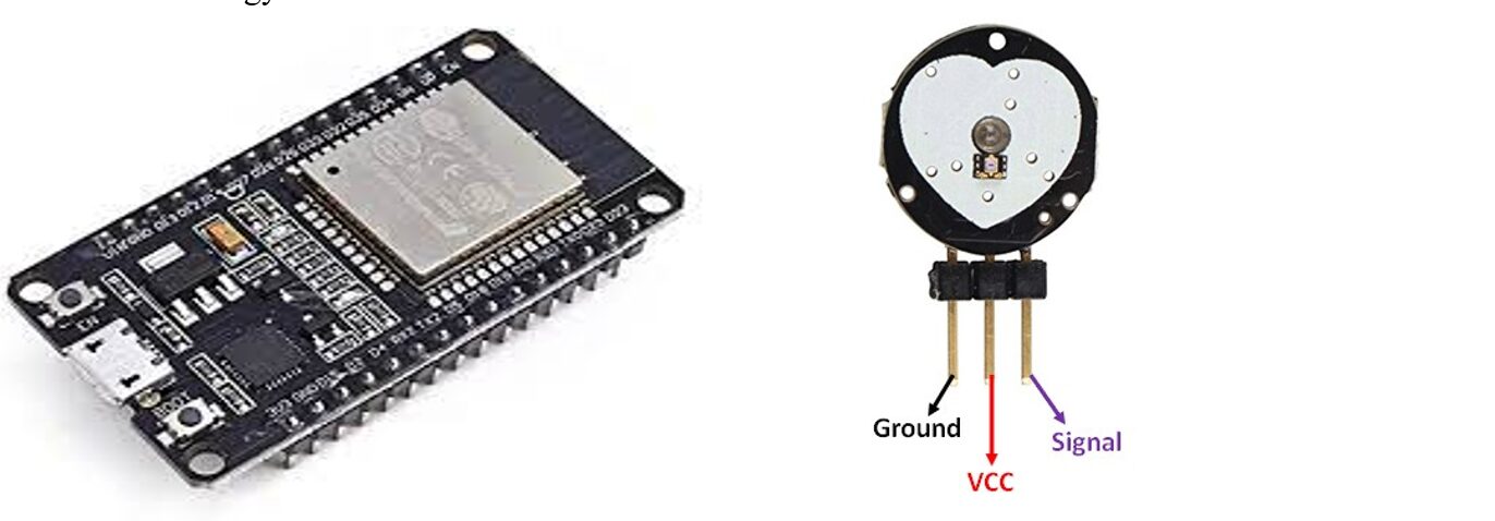
The ESP32 is a strong microcontroller that is developed by Expressif company in China; and it is a great option for Internet of Things projects because it has integrated WiFi and Bluetooth capabilities. It is appropriate for battery-operated devices since it has several GPIO pins, supports a range of communication protocols, and has a low power usage mode.
While the pulse sensor detects changes in light absorption in blood vessels to measure heart rate, it is a common component of wearable health devices and is easily integrated into this ESP32 project. On the other hand, the DHT11 sensor is a low-cost digital sensor for measuring temperature and humidity. It provides a calibrated digital output and is easy to interface with any microcontroller. Hence our choice for it to read the user’s body temperature and skin humidity.
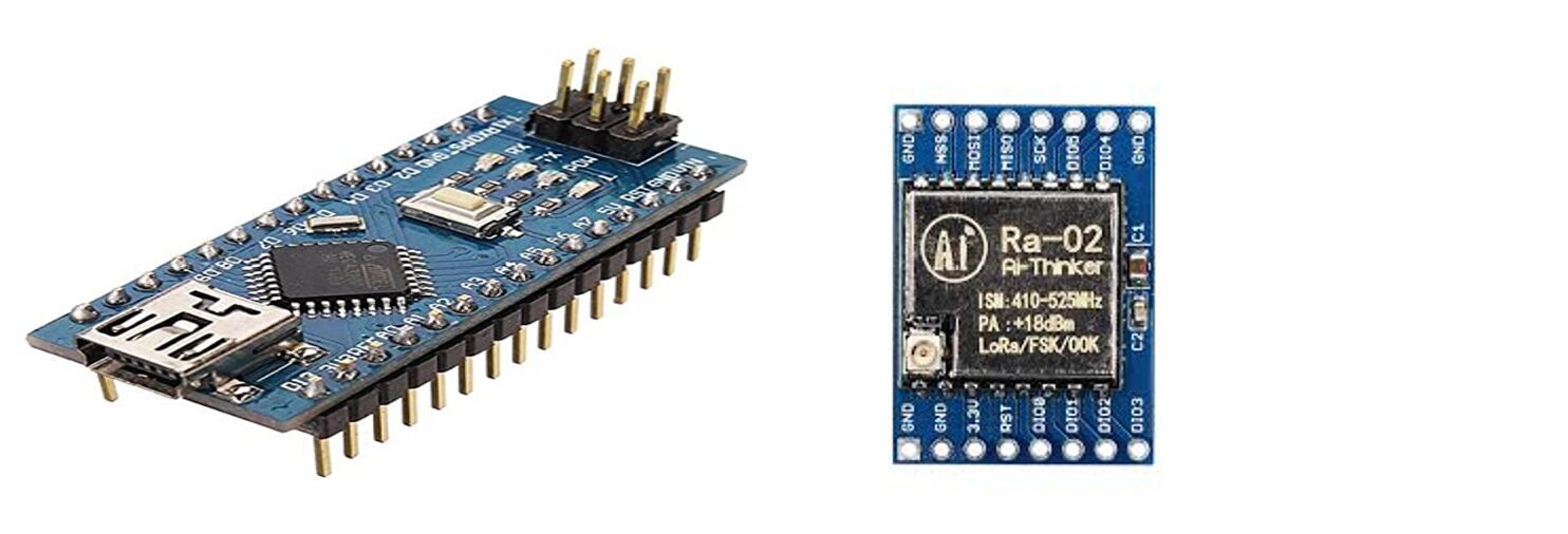
For this IoT Health Monitoring with LoRa technology project, we needed to transmit the readings of the sensors from the user to a qualified personnel, say perhaps a doctor or a health professional wirelessly without having to incur the cost of data via internet. For such long-distance wireless communication, LoRa (Long Range) modules are utilized. They are renowned for their low power consumption and long-range data transmission capabilities (up to 10 km in open regions), and they operate in the unlicensed ISM bands.
The receiver side of this project uses an Arduino Nano , this board is a compact version of the Arduino Uno and is often used in projects where space is limited. It has fewer GPIO pins than the Uno but is more than sufficient for this project.
The LCD display will be used to show the temperature, humidity, and pulse rate values received by the Arduino Nano. The module was the 16×4 version and it worked very well for us to display all the parameters we received. , depending on the user’s preference.
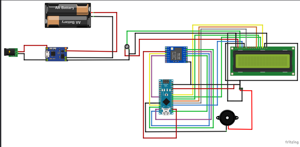
The Schematic Diagram for the IoT Pulse Rate Monitoring
Explanation of the Schematic Diagram
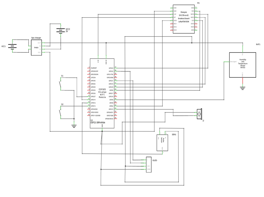
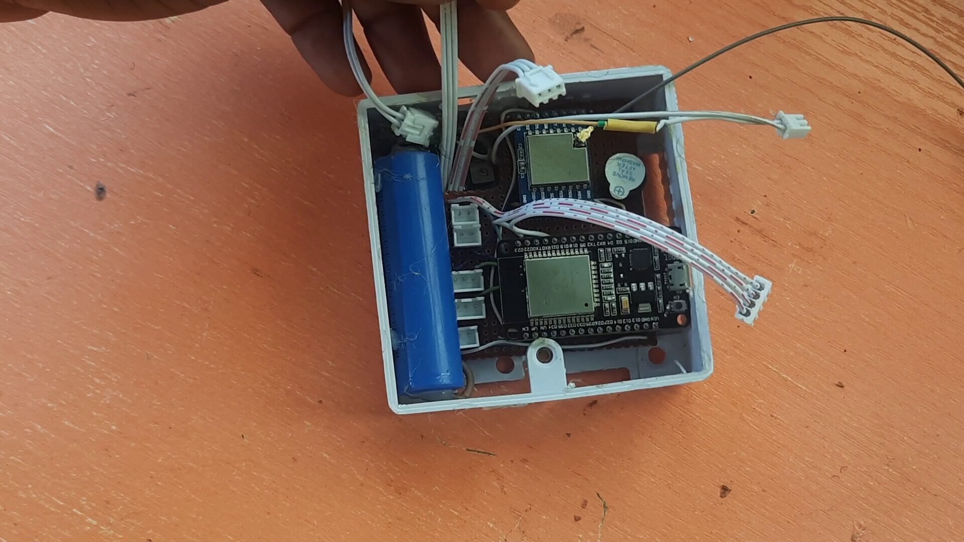
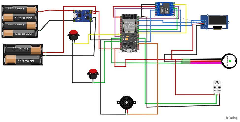
The schematic diagram showed that the IoT Health Monitoring with LoRa technology project design for the transmitter was built around the ESP32 Development (dev) board. The ESP32 is powered by the output of the LiPo battery charging module. Which in turn was powered by the 3.3V LiPo battery. The type of circuitry found in the module made it very easy for us to get an output of 5V by regulating the onboard potentiometer on the module.
- IoT Based Automatic Fish Pond Feeder
- IoT Based Health Monitoring System Using Arduino
- IoT Pump Control Irrigation System Using ESP32 Arduino
This 5V logic is then paralleled across the sensors that used 5V as their input logic voltage. This is the digital humidity and temperature sensor (DHT11) and the pulse/heart rate sensor module. The ESP32 has an onboard regulator that can output 3.3V and this is connected to the LoRa module since it can only support 3.3V logic voltage for its operation. All the Ground (GND) pins are connected together to ensure the system works as expected. The 0.96 inch OLED (organic light emitting diode) consumes 5V and can still work on 3.3V but we connected it to the 5V power rail to ensure optimum performance.
Connection of the LoRa Module
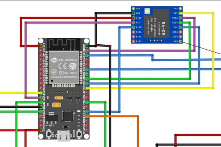
The connection of the LoRa module was done using the Serial Peripheral Interface (SPI). The LoRa module has for SPI pins. The MISO (master in, slave out) which was connected to GPIO (general purpose input output) 19 on the ESP32 dev board, MOSI (Master out, slave in) which was connected to GPIO pin 22 on the ESP32, SCK (serial clock) is connected GPIO 18. tHe Input output (IO) 0 on the LoRa module is connected to the GPIO pin 2 on the ESP32, whereas, the reset pin of the LoRa module is connected to the ESP32 GPIO pin 14.
Explanation for DHT11 Sensor Connection
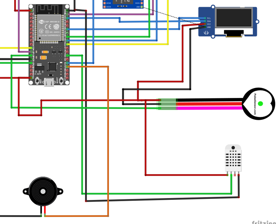
The ESP32 dev board read the dht11 connected to its GPIO pin 21, the digital input pin of the DHT11 that is. The power rails of the DHT11 sensor is connected to the 5V logic. For the DHT11 to work precisely, a 10kΩ precision resistor is added by connected it between the Vcc and the GND pins respectively.
The Arduino Nano Board (Receiver Side)
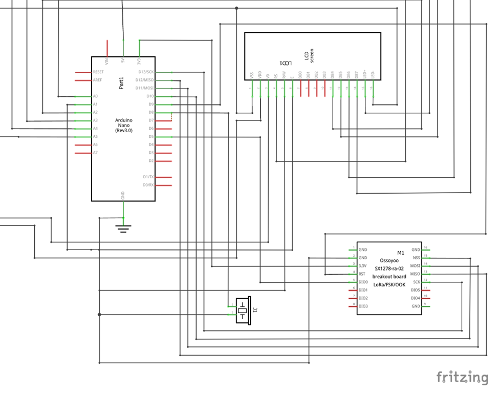
Since the connection needed an SPI protocol, the SPI buses on the Arduino Nano were used as shown in the schematic diagram above. Once these connections were ensured, the program code below was uploaded into the Arduino Nano to receive data from the transmitter side of the project.
The both systems are running on rechargeable power option. The type of power modules used in the transmitter and the receiver side allowed us to charge the 3.3V LiPo battery and get 5V output to power and run each system effectively.
Programming the Project Design
Arduino Program Code for the ESP32 (Transmitter Side)
#include <WiFi.h>
#include "ThingSpeak.h"
#include <SPI.h>
#include <LoRa.h>
#include "DHT.h"
//
#include <Wire.h>
#include <Adafruit_GFX.h>
#include <Adafruit_SSD1306.h>
//
#define SCREEN_WIDTH 128 // OLED display width, in pixels
#define SCREEN_HEIGHT 64 // OLED display height, in pixels

// Declaration for an SSD1306 display connected to I2C (SDA, SCL pins)
Adafruit_SSD1306 display(SCREEN_WIDTH, SCREEN_HEIGHT, &Wire, -1);


const char* ssid = "Galaxy A51 917E";   // your network SSID (name)
const char* password = "ancsucre21";   // your network password
//set the instance for High BP and Low BP
#define HBPpin 13
#define LBPpin 27

WiFiClient  client;

unsigned long myChannelNumber = 1;
const char * myWriteAPIKey = "MTL2US26KL1BFUT1";
// Timer variables
unsigned long lastTime = 0;
unsigned long timerDelay = 10000;

//define where the heart rate sensor is connected
#define sensorPinout 12
int sensorPin;
// Digital pin connected to the DHT sensor
#define DHTPIN 4
//define where the buzzer is connected
#define buzzerPin 15

int counter = 0;
bool panic;
float h, t, f;
int sensorAnalog,heartRate, checkHBP, checkLBP = 0;
String greeting = "hello";

//define the pins used by the transceiver module
#define ss 5
#define rst 14
#define dio0 2
 // DHT 11
#define DHTTYPE DHT11
// as the current DHT reading algorithm adjusts itself to work on faster procs.
DHT dht(DHTPIN, DHTTYPE);

void loraSetup(){
  while (!Serial);
  Serial.println("LoRa Sender");

  //setup LoRa transceiver module
  LoRa.setPins(ss, rst, dio0);

  //replace the LoRa.begin(---E-) argument with your location's frequency
  //433E6 for Africa & Asia
  //866E6 for Europe
  //915E6 for North America
  while (!LoRa.begin(433E6)) {
    Serial.println(".");
    delay(500);
  }
   // Change sync word (0xF3) to match the receiver
  // The sync word assures you don't get LoRa messages from other LoRa transceivers
  // ranges from 0-0xFF
  LoRa.setSyncWord(0xF3);
  Serial.println("LoRa Initializing OK!");
}

void thingspeakSetup(){
  WiFi.mode(WIFI_STA);
  ThingSpeak.begin(client);  // Initialize ThingSpeak
// Connect or reconnect to WiFi
    if(WiFi.status() != WL_CONNECTED){
      Serial.print("Attempting to connect");
      while(WiFi.status() != WL_CONNECTED){
        WiFi.begin(ssid, password);
        delay(5000);
      }
      Serial.println("nConnected.");
    }
}

void setup() {
//initialize Serial Monitor
  Serial.begin(115200);
//begin the dht sensor
 dht.begin();
//start the thingspeak setup
thingspeakSetup();
//start the LoRa setup
loraSetup();
//set ur inputs and outouts make the buzzer an output
pinMode(buzzerPin, OUTPUT);
pinMode(HBPpin, INPUT_PULLUP);
pinMode(LBPpin, INPUT_PULLUP);
//check for display
if(!display.begin(SSD1306_SWITCHCAPVCC, 0x3C)) { // Address 0x3D for 128x64
    Serial.println(F("SSD1306 allocation failed"));
    for(;;);
  }
  delay(2000);
  display.clearDisplay();

  display.setTextSize(1);
  display.setTextColor(WHITE);
  // Display static text at column 10 row 0
  display.setCursor(0, 10);
  display.println("  WELCOME SOPHIA");
  display.setCursor(0, 20);
  display.println("  LoRa & IoT BASED ");
  display.setCursor(0, 30);
  display.println(" PROJECT ");
  display.display();
}

int heartRateReader(){
  sensorPin = analogRead(sensorPinout);                 // wait for a second
  //  delay(500);
  return sensorPin;
}

float dhtSensor(){
  // Reading temperature or humidity takes about 250 milliseconds!
  // Sensor readings may also be up to 2 seconds 'old' (its a very slow sensor)
   h = dht.readHumidity();
  // Read temperature as Celsius (the default)
   t = dht.readTemperature();
  // Read temperature as Fahrenheit (isFahrenheit = true)
   f = dht.readTemperature(true);
return h, t, f;
  // Check if any reads failed and exit early (to try again).
  if (isnan(h) || isnan(t) || isnan(f)) {
    Serial.println(F("Failed to read from DHT sensor!"));
  }

  // Compute heat index in Fahrenheit (the default)
  float hif = dht.computeHeatIndex(f, h);
  // Compute heat index in Celsius (isFahreheit = false)
  float hic = dht.computeHeatIndex(t, h, false);
}

int checkHeartCondition(){
 checkHBP = digitalRead(HBPpin);
 checkLBP = digitalRead(LBPpin);
 return checkHBP, checkLBP;
}

void panicDisplay(){
  display.clearDisplay();
    display.setTextColor(SSD1306_WHITE);        // Draw white text
 display.setCursor(0, 5);
 //display.setTextSize(2);
 display.setTextSize(1);
 display.print("Abnorma Levels Detected. nContact a Medical Expert Soon ");
 display.display();
}

int raiseAlarm(){
  checkHeartCondition();
  dhtSensor();

   if(sensorPin == 0){
    sensorPin = 60;
    digitalWrite(buzzerPin, LOW);
    panic = false;
  }

  if(checkHBP == LOW){
    sensorPin = 240;
    digitalWrite(buzzerPin, HIGH);
    //panicDisplay();
    panic = true;
  }

  if(checkLBP == LOW){
    sensorPin = 0;
    digitalWrite(buzzerPin, HIGH);
    //panicDisplay();
    //panic = true;
  }

  //check if the alrm should sound
  if((h >= 100.00) || (t >= 50.00)){
    digitalWrite(buzzerPin, HIGH);
    //panicDisplay();
    panic = true;
  }

  else{
    sensorPin /= 2;
    panic = false;
  }

  return panic, sensorPin;
}

void oledDisplay(){
  raiseAlarm();

  if(panic != true){
    display.clearDisplay();
    display.setTextColor(SSD1306_WHITE);        // Draw white text

 display.setCursor(0, 5);
 display.setTextSize(1);
 display.print("H.R: ");
 display.setTextSize(2);
 //display.setCursor(5, 5);
 display.print(sensorPin);
  display.setTextSize(1);
  display.print(" bpm");


  display.setCursor(0, 25);
  display.setTextSize(1);
 display.print("B.H: ");
 display.setTextSize(2);
  display.print(h);
  display.setTextSize(1);
  display.print(" %");

  display.setCursor(0, 45);
  display.setTextSize(1);
 display.print("B.T: ");
 display.setTextSize(2);
  display.print(t);
  display.setTextSize(1);
  display.print("'C");

   display.display();
  }

  else IF (panic == true){
    display.clearDisplay();
    display.setTextColor(SSD1306_WHITE);        // Draw white text
    display.setTextSize(1);
    display.print("SOMETHING IS WRONG nPLEASE SEE A DOCTORnSOON!!!");
    display.display();

  }
}

void sendTruLoRa(){
  Serial.println("<<<Sending packet>>>");
  Serial.print("hum: ");Serial.print(h);
  Serial.print(" temp: "); Serial.print(t);
  Serial.print(" heart rate: ");
  Serial.println(sensorPin);

  //Send LoRa packet to receiver
  LoRa.beginPacket();
  //use delimiters
  LoRa.print('<');
  LoRa.print(greeting); LoRa.print(',');
  LoRa.print(h);LoRa.print(',');
  LoRa.print(t);LoRa.print(',');
  LoRa.print(sensorPin);LoRa.print('>');
  LoRa.endPacket();

}


void sendToThingspeak(){
 raiseAlarm();
  oledDisplay();

  if ((millis() - lastTime) > timerDelay) {
// pieces of information in a channel.  Here, we write to field 1.
    int x = ThingSpeak.writeField(myChannelNumber, 1, sensorPin, myWriteAPIKey);
    int y = ThingSpeak.writeField(myChannelNumber, 2, h, myWriteAPIKey);
    int z = ThingSpeak.writeField(myChannelNumber, 3, t, myWriteAPIKey);
    //uncomment if you want to get temperature in Fahrenheit
    //int x = ThingSpeak.writeField(myChannelNumber, 1, temperatureF, myWriteAPIKey);

    if(x == 200){
      Serial.println("Channel update successful.");
    }
    else{
      Serial.println("Problem updating channel. HTTP error code " + String(x));
    }
    lastTime = millis();
    }
 delay(1000);
//raiseAlarm();
//oledDisplay();
sendTruLoRa();
}

void loop() {
  //heartRateReader();

 sendToThingspeak();
 delay(200);
}
Given the condition that no test patient would be allowed to go into cardiac arrest for this project, two push buttons were used as shown above to simulate these conditions physically. The push buttons when depressed acted as going into a high pulse rate and low pulse rate. The program code allowed us to read the states of the pushbuttons.
The code above when uploaded and the serial monitor opened. The results show the received data from the transmitter end. And each count that was sent for each burst of transmitted data.
Arduino Program Code for the Arduino Nano board (Receiver Side)
#include <SPI.h>
#include <LoRa.h>

//define the pins used by the transceiver module
#define ss 5
#define rst 14
#define dio0 2

void setup() {
  //initialize Serial Monitor
  Serial.begin(115200);
  while (!Serial);
  Serial.println("LoRa Receiver");

  //setup LoRa transceiver module
  LoRa.setPins(ss, rst, dio0);

  //replace the LoRa.begin(---E-) argument with your location's frequency
  //433E6 for Asia
  //866E6 for Europe
  //915E6 for North America
  while (!LoRa.begin(866E6)) {
    Serial.println(".");
    delay(500);
  }
   // Change sync word (0xF3) to match the receiver
  // The sync word assures you don't get LoRa messages from other LoRa transceivers
  // ranges from 0-0xFF
  LoRa.setSyncWord(0xF3);
  Serial.println("LoRa Initializing OK!");
}

void loop() {
  // try to parse packet
  int packetSize = LoRa.parsePacket();
  if (packetSize) {
    // received a packet
    Serial.print("Received packet '");

    // read packet
    while (LoRa.available()) {
      String LoRaData = LoRa.readString();
      Serial.print(LoRaData);
    }

    // print RSSI of packet
    Serial.print("' with RSSI ");
    Serial.println(LoRa.packetRssi());
  }
}
The LCD (liquid crystal display) module was connected using the 4-bit communication protocol that means that only 4 wires were needed for the writing of data from the Nano board to the LCD module. The Register Select (RS) and the Enable (E) was connected to the A2 and A1 respectively while the data pins D4 through D7 was connected to A0, A3 through A5 as shown in the figure above.
The follow code was used to test the LCD module to know if the connections made were correct when writing data to the display. The Read/Write (RW), Vss and LED- were connected to the ground (GND) pin of the 5V power rails whereas the Vdd and LED+ were connected to the Vcc pin of the 5V power rail.
Testing and Results
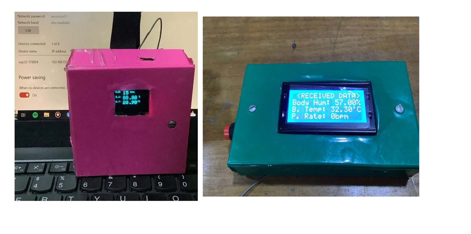
The project works very well, and it can send to both the receiver and also to the IoT dashboard when it can be further analyzed and remotely monitored. We included a Velcro patch to the transmitter side so that it can be strapped to the wrist to allow easy reading of the human body temperature and skin humidity.
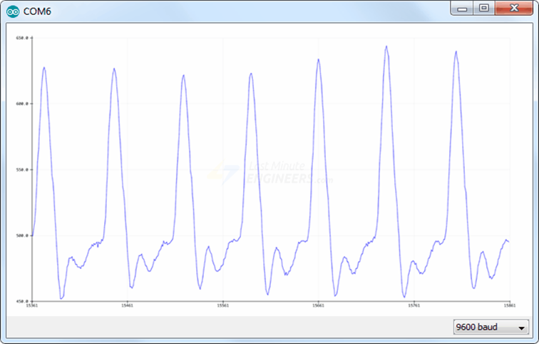
The image above shows the serial plotter of the pulse sensor when it is put on by the user. We can see the pulse that is being detected as it shows up on the screen.
Conclusion
The IoT Pulse, Body temperature, skin humidity monitoring project was a success within the scope of the experiment and design carried out. We would love to know if you did this project and was successful. The Iot Platform can be changed from thingspeak to Blynk cloud but bear in mind that Blynk only allow for 5 parameters on their free tier whereas thingspeak allows for 10 on each channel with a maximum channel of 4 for the free tier plan.
Leave us a comment below if you tried to replicate this project and it worked for you. Perhaps you made some modifications and the project became some awesome. We would to hear from you. See you on the next project tutorial section.
You May Also like…
- How to Make Money on Facebook Marketplace
- Should Teens Be Allowed to Obtain Birth Control Pills?
- Famous Celebrities Who Battled and Beat Cancer
- Celebrities Who Don’t Believe In God
Frequently Asked Questions on IoT Pulse Rate Monitoring Project
1. How does the system handle data loss during transmission?
The system does not have built-in error correction, so if data is lost during transmission, it won’t be recovered. However, you can implement a checksum or acknowledgment mechanism in the code to ensure data integrity and request retransmission if errors are detected.
2. Can I monitor the data on a mobile device?
Yes, you can monitor the data on a mobile device by accessing the Thingspeak platform through a web browser or by using a mobile app that supports Thingspeak. Custom apps can also be developed using Thingspeak’s API for more tailored monitoring.
3. What are the potential applications of this project beyond health monitoring?
Beyond health monitoring, this project can be adapted for various environmental monitoring applications, such as tracking temperature and humidity in agricultural settings, remote weather stations, or even industrial environments where real-time data is crucial.
4. How can I ensure the accuracy of the sensor readings?
To ensure accuracy, you should regularly calibrate the sensors, particularly the DHT11, which can have slight variances. You can also compare the readings with a reference sensor and apply correction factors in the code if needed.
5. What are the benefits of using ESP32 over other microcontrollers like Arduino?
The ESP32 offers built-in WiFi and Bluetooth capabilities, making it ideal for IoT projects like this one. It also has a more powerful processor and more memory compared to traditional Arduino boards, allowing for more complex operations and better performance in real-time applications.

