In today’s tech-driven world, taking charge of your health has never been easier. Enter the exciting realm of IoT-based health monitoring systems, where affordable and accessible tools like Arduino empower you to track your vital signs in real-time, right from your home. Let’s delve into the fascinating world of building your own Arduino-powered health monitoring system, unlocking a personalized path to wellness, a Health Monitoring System.
Introduction
Imagine keeping a constant eye on your heart rate, temperature, or even blood pressure – without expensive equipment or hospital visits. Arduino makes this dream a reality. By harnessing the power of these tiny microcontrollers, you can create a custom health monitoring system that seamlessly integrates into your daily life.
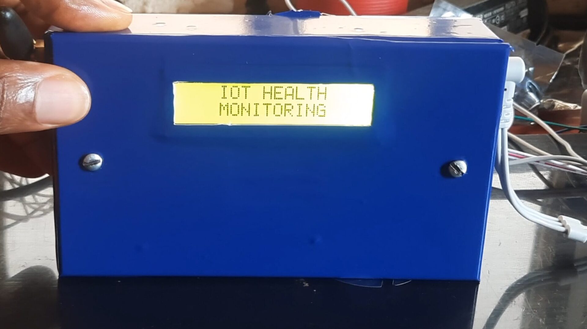
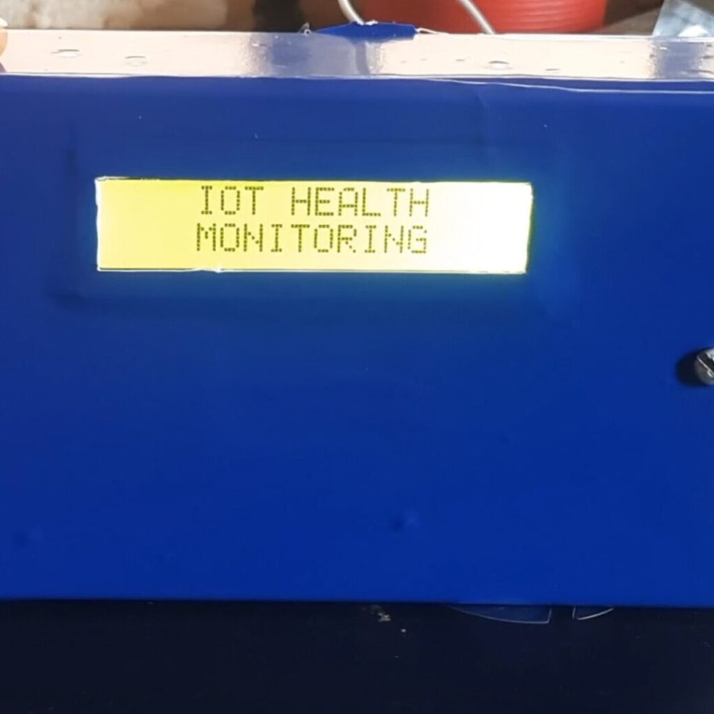
In this post will guide you through the exhilarating journey of building your own Arduino-based health monitoring system, empowering you to track key health parameters with ease and confidence. Whether you’re a tech enthusiast or simply someone committed to proactive health management, this DIY project opens a world of possibilities. This is an Internet of Things (IoT) based hence the design would use GSM module to send these reading to the Thingspeak dashboard where it can be remotely monitored globally.
Having a rechargeable backup battery power system, this will also send SMS to predefined person (s) when there is abnormal readings and give out a warning sound at this extreme readings. We will be able to use DIY based sensors like pulse rate sensor to measure pulse, ECG sensor to measure electrocardiograph, heart rate sensor to measure the heart beat. And we can also add a contact type temperature sensor like the stainless steel plated DS18B20 Dallas temperature sensor to measure the body temperature too .
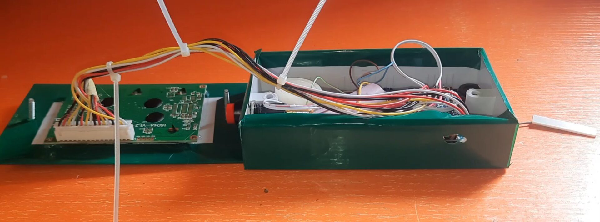
System Design and Hardware
The heart of your health monitoring system lies in the powerful combination of Arduino and health sensors. For us, these DIY sensors doesn’t offer as much accuracy as we would want them, except for the Dallas temperature sensor. Below is the table that shows the bulk of materials and components for the project design.
| ITEM DESCRIPTION | QUANTITY |
| LiPo CHARGING MODULE | 1 |
| LCD Module | 1 |
| 3x6INCH PATRESS BOX | 1 |
| Connector | 3 |
| RESISTORS | 2 |
| CONNECTING WIRES | 3 yards |
| VERO BOARD | 1 |
| ECG SENSOR | 1 |
| LIPO BATTERY | 1 |
| SOLDER | 1 |
| SOLDERING IRON | 1 |
| Buzzer | 1 |
| SIM800L GSM MODULE | 1 |
| PULSE/HEART RATE SENSOR | 1 |
| FEMALE HEADERPIN | 2 |
| MISCELLANEOUS | |
| TOTAL |
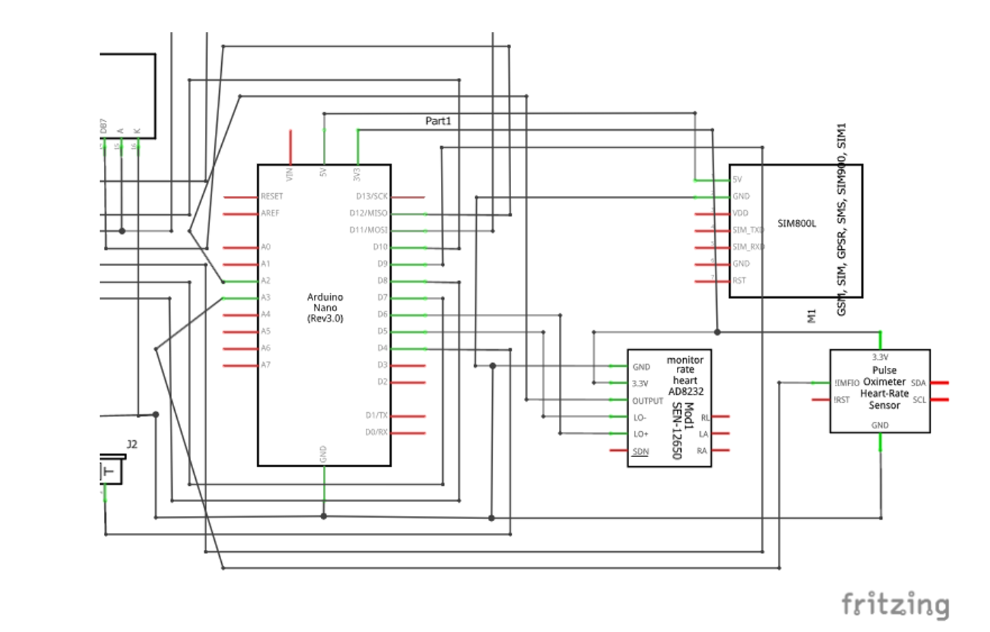
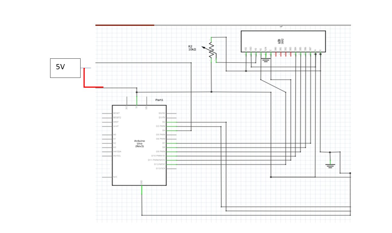
The Circuit Diagram for IoT Based Health Monitoring System Project Design
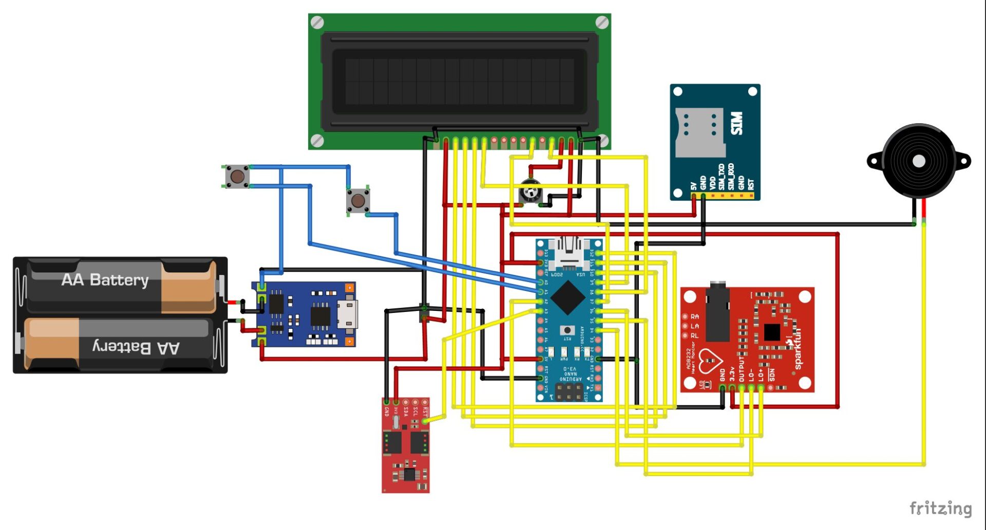
Explanation of the Circuit Diagram
The pulse sensor enables measurement and reading of heart rate data or pulse rate, a crucial parameter for diagnosing and researching aspects related to human health, anxiety levels, activity, or physical health. The pulse rate sensor is composed of two straightforward optical heart rate sensors with noise reduction and amplification.
The sensor is made up of a photodiode and an infrared light-emitting diode (LED). Infrared light from the LED is transmitted into the fingertip and reflected off the blood inside finger arteries. To determine the current heartbeat rate and display it on the LCD panel, the system uses a heartbeat sensor. The Arduino Nano microcontroller is a component of the transmitting circuit, which is powered by a 5V DC development board and interfaced to an LCD display. Like the sending circuit, the receiving circuit uses an RF receiver and Arduino Nano microcontroller and is also powered by a 5V DC development board.
The receiver circuit includes an LED light and a buzzer, which serve the purpose of alerting the individual responsible for monitoring the patient’s heart rate. Whenever there is a deviation in the patient’s heart rate from the established normal level, both the LED light and the buzzer are triggered for notification. Operators can monitor all patients from a single location while seated. The sensor needs 20 seconds to determine the heart rate value and even in normal circumstances, alerts regarding the patient’s heart rate will be delivered to the medical staff in care of them by SMS and emergency calls which is made possible by the GSM module. BPM means Beat Per Minute.
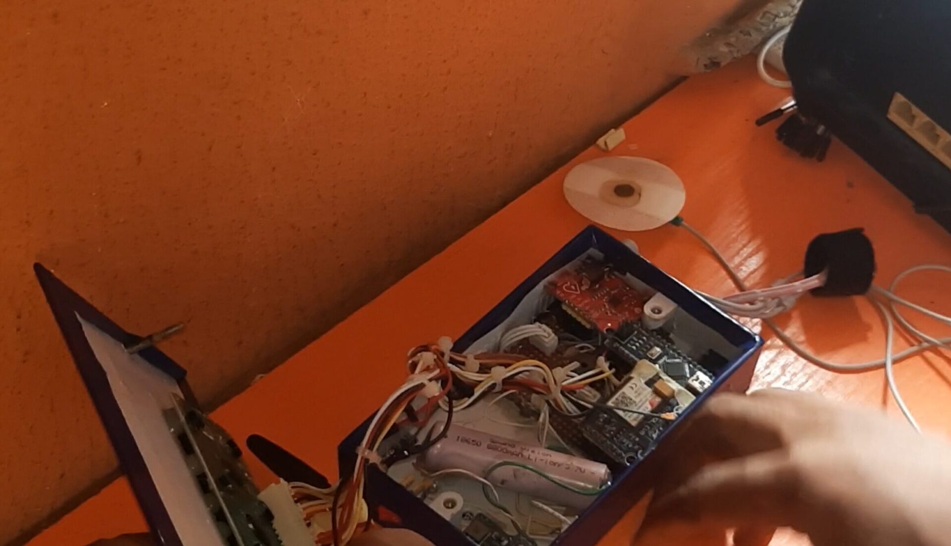
The Arduino Nano board is the control center of the project design. From the schematic diagram above, the Nano board is connected to the GSM module through serial communication. This type of serial communication is called software serial. It involves using a digital pin on the Nano board that is not the hardware Universal Asynchronous Receiver Transmitter (UART) pins. The receiver (Rx) and the transmitter (Tx) pins are then assigned in the code.
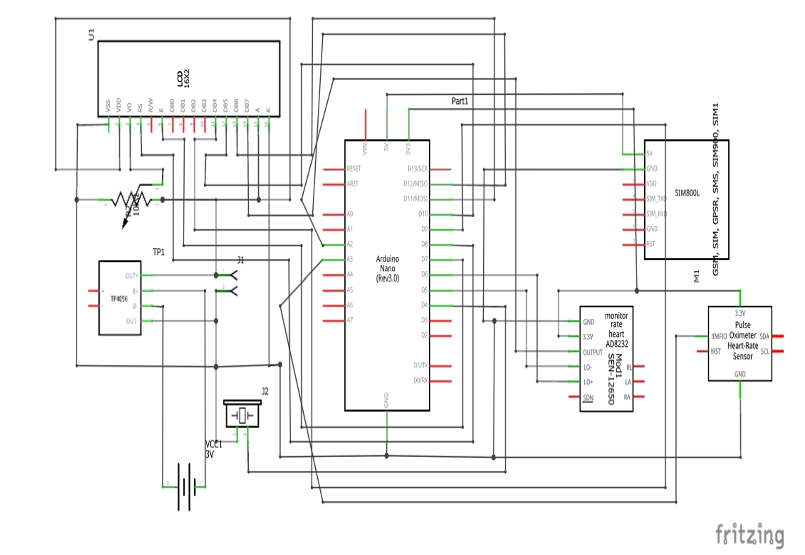
In the given diagram, it can be observed that the Rx pin of the Arduino Nano is linked to the TX pin of the SIM800L GSM module, while the Tx pin of the Arduino Nano is connected to the Rx pin of the SIM800 GSM module. The SIM800 module used here is the EVB breakout board type hence it used the same logic voltage level as the Nano board, 5V. The inclusion of the GSM module is to gain internet access to push the sensor readings to the cloud platform for worldwide tracking and view. It also helped to send emergency alerts like calls and SMS to the health professional in charge of the patient.
The DIY ECG sensor works on 3.3V logic, hence it was connected to the 3.3V rail on the Arduino nano board. The DIY ECG sensor had a LO+ and LO- pins where the digital pin 6 (D6) and the digital pin 5 (D5) were connected respectively. These pins were used to check that the ECG sensors were not reading. The analog output pins on the DIY ECG sensor are connected to analog pin 3 (A3) on the Arduino Nano. This was used to take the analog readings of the heart’s rhythm.
The pulse rate sensor works on both 3.3V and 5V logic voltage, however, to get the best performance out of it; a 5V power rail was used on it. The analog pin of the sensor is connected to analog pin 2 on the Arduino Nano board. This allows for reading the pulse rate of the heart and display it on the screen.
To solve the problem of high pulse rate or low heart rate, a buzzer was added that would instantaneously give an alert by beeping a noisy sound, call the attention of a loved one or that of the medical practitioner to such spikes in heart rate or under normal heart beats. Lastly, since there was no patient with High Blood Pressure (High BP) or Low BP, we had to use a pushbutton to simulate for this extreme cases.
Read Also…
- Arduino Home Automation Using ESP32 Cam and Blynk
- How to Design IoT Based Air Quality Monitoring For COPD Patients
- How to build a Smart Hydroponics IoT Project
Software Development: The Brain of the Health Monitor System
Setting Up the Thingspeak IoT Dashboard

MathWorks created the Internet of Things (IoT) platform called ThingSpeak. Users of this cloud-based service can gather, examine, and visualize data from IoT devices. The platform provides a storage architecture so that the gathered data may be managed and stored. To organize and categorize data streams from various devices or sources, users can build several channels
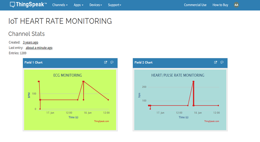
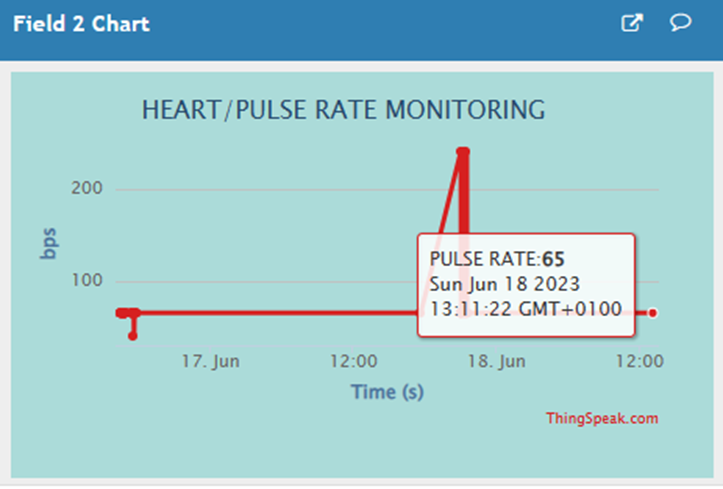
Hence we really only needed the two sensor readings which were the ECG sensor and the heart/pulse rate sensor. This would show us a history of what each sensor was saying each time it was turned on and used. Provided the GSM module has internet access to transmit data to the Thingspeak server.
Health Monitoring System: The Arduino Source Code
#include <SoftwareSerial.h>
#include <LiquidCrystal.h>
#include <SoftwareSerial.h>
SoftwareSerial cell(2, 3);
const int rs = 8, en = 7, d4 = 9, d5 = 10, d6 = 11, d7 = 12;
LiquidCrystal lcd(rs, en, d4, d5, d6, d7);
#define buttonHeartRatePin A2
#define buttonPulseRatePin A3
#define LOpositive 6
#define LOnegative 5
#define buzzerPin 4
int ecgAnalogPin,readecgAnalogPin, readpulseAnalogPin, pulseAnalogPin;
int readHBPButton, readLBPButton;
// constants won't change. Used here to set a pin number:
const int ledPin = LED_BUILTIN; // the number of the LED pin
// Variables will change:
int ledState = LOW; // ledState used to set the LED
// Generally, you should use "unsigned long" for variables that hold time
// The value will quickly become too large for an int to store
unsigned long previousMillis = 0; // will store last time LED was updated
// constants won't change:
const long interval = 3000;
void setup(){
lcd.begin(16, 2);
//Begin serial communication with Arduino and Arduino IDE (Serial Monitor)
Serial.begin(9600);
//Begin serial communication with Arduino and SIM800L
cell.begin(9600);
//print a welcome msg on the lCD
lcd.setCursor(0, 0);
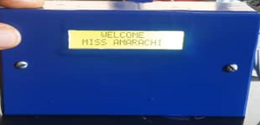
lcd.print(" WELCOME ");
lcd.setCursor(0,1);
lcd.print(" MISS AMARACHI ");
delay(3000);
lcd.clear();
lcd.setCursor(0, 0);
lcd.print(" IOT HEART RATE");
lcd.setCursor(0, 1);
lcd.print(" MONITORING ");
delay(3000);
lcd.clear();
lcd.setCursor(0,0);
lcd.print(" MONITORING ");
lcd.setCursor(3, 1);
lcd.print(" PROJECT ");
delay(3000);
Serial.println("Initializing...");
delay(1000);
Serial.println("done");
// initialize digital pin LED_BUILTIN as an output.
pinMode(buttonHeartRatePin, INPUT_PULLUP);
pinMode(buttonPulseRatePin, INPUT_PULLUP);
pinMode(buzzerPin, OUTPUT);
pinMode(ledPin, OUTPUT);
lcd.clear();
}
int panicButtons(){
readHBPButton = digitalRead(buttonHeartRatePin);
readLBPButton = digitalRead(buttonPulseRatePin);
return readHBPButton, readLBPButton;
Serial.println("button ECG is: " +String(readHBPButton)+ " button pulseRate is: " + String(readLBPButton));
delay(500);
}
int ecgSensor(){
panicButtons();
if ((digitalRead(LOpositive) == 1) || (digitalRead(LOnegative) == 1)) {
Serial.println('!');
}
else{
ecgAnalogPin = analogRead(A1);
readecgAnalogPin = ecgAnalogPin/2;
}
return readecgAnalogPin;
}
int pulseRate(){
pulseAnalogPin = analogRead(A0);
readpulseAnalogPin = pulseAnalogPin/2;
return readpulseAnalogPin;
}
int checkVitals(){
ecgSensor();
pulseRate();
panicButtons();
//display on the LCD
//check for the conditions of abnormality
if(readHBPButton == LOW){
Serial.println('physical anomaly detected. High blood pressure rate');
lcd.clear();
lcd.setCursor(2, 0);
lcd.print("ALERT! ALERT!!");
lcd.setCursor(0, 1);
lcd.print("HIGH BP DETECTED!");
digitalWrite(buzzerPin, HIGH);
sendSMS();
readpulseAnalogPin = 240;
readecgAnalogPin = 180;
}
else if(readLBPButton == LOW){
Serial.println('physical anomaly detected. High blood pressure rate');
lcd.clear();
lcd.setCursor(2, 0);
lcd.print("ALERT! ALERT!!");
lcd.setCursor(0, 1);
lcd.print("LOW BP DETECTED!");
digitalWrite(buzzerPin, HIGH);
sendSMS();
readpulseAnalogPin = 40;
readecgAnalogPin = 0;
}
else{
if (readecgAnalogPin == 0){
readecgAnalogPin = 60;
}
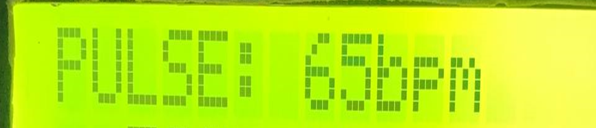
readpulseAnalogPin = 65;
digitalWrite(buzzerPin, LOW);
lcd.clear();
lcd.setCursor(0, 0);
lcd.print("PULSE: " + String(readpulseAnalogPin) + "bpm");
lcd.setCursor(0, 1);
lcd.print(" ECG: " + String(readecgAnalogPin) + "mm/s");
Serial.println("Pulse Rate: " + String(readpulseAnalogPin) + " Blood Pressure: " + String(readecgAnalogPin));
delay(500);
}
sendToThingspeak();
return readpulseAnalogPin, readecgAnalogPin;
}
void sendToThingspeak(){
Serial.println("Now in: " + String(readpulseAnalogPin) + " and " + String(readecgAnalogPin));
if (cell.available())
Serial.write(cell.read());
cell.println("AT");
delay(1000);
cell.println("AT+CPIN?");
delay(200);
cell.println("AT+CREG?");
delay(200);
cell.println("AT+CGATT?");
delay(1000);
cell.println("AT+CIPSHUT");
delay(200);
cell.println("AT+CIPSTATUS");
delay(2000);
cell.println("AT+CIPMUX=0");
delay(200);
ShowSerialData();
cell.println("AT+CSTT=\"web.gprs.mtnnigeria.net\"");//start task and setting the APN,
delay(200);
ShowSerialData();
cell.println("AT+CIICR");//bring up wireless connection
delay(300);
ShowSerialData();
cell.println("AT+CIFSR");//get local IP adress
delay(200);
ShowSerialData();
cell.println("AT+CIPSPRT=0");
delay(100);
ShowSerialData();
cell.println("AT+CIPSTART=\"TCP\",\"api.thingspeak.com\",\"80\"");//start up the connection
delay(600);
ShowSerialData();
cell.println("AT+CIPSEND");//begin send data to remote server
delay(400);
ShowSerialData();
String str="GET https://api.thingspeak.com/update?api_key=05G6PILTK6BQQIUO&field1=" + String(readecgAnalogPin) +"&field2="+String(readpulseAnalogPin);
Serial.println(str);
cell.println(str);//begin send data to remote server
delay(400);
ShowSerialData();
cell.println((char)26);//sending
delay(500);//waitting for reply, important! the time is base on the condition of internet
cell.println();
ShowSerialData();
cell.println("AT+CIPSHUT");//close the connection
delay(100);
//ShowSerialData();
}
void loop(){
unsigned long currentMillis = millis();
if (currentMillis - previousMillis >= interval) {
// save the last time you blinked the LED
previousMillis = currentMillis;
// if the LED is off turn it on and vice-versa:
if (ledState == LOW) {
ledState = HIGH;
checkVitals();
} else {
ledState = LOW;
// sendToThingspeak();
}
// set the LED with the ledState of the variable:
digitalWrite(ledPin, ledState);
}
}
void sendSMS(){
sendSMS("+2348103131467", "Hello Doctor.\nPatient Emmergency Detected! Body Health Parameters Anomality Readings Received.\nKindly Attend to Patient.\nThank You.");
delay(500);
updateSerial();
delay(30000);
}
void makeCall(){
cell.println("AT"); //Once the handshake test is successful, it will back to OK
updateSerial();
cell.println("ATD+ +2348103131467;"); // change ZZ with country code and xxxxxxxxxxx with phone number to dial
updateSerial();
delay(20000); // wait for 20 seconds...
cell.println("ATH"); //hang up
updateSerial();
}
void sendSMS(char receiver[11], char content[140]){
cell.println("AT+CMGF=1");
delay(1000);
cell.print("AT+CMGS=");
delay(5);
cell.print(char(34));
delay(5);
cell.print(receiver);
delay(5);
cell.println(char(34));
delay(5);
cell.print(content);
delay(50);
cell.println(char(26));
delay(2000);
Serial.println("Done");
delay(3000);
}
void updateSerial(){
delay(5);
while (Serial.available())
{
cell.write(Serial.read());//Forward what Serial received to Software Serial Port
}
while(cell.available())
{
Serial.write(cell.read());//Forward what Software Serial received to Serial Port
}
}
void ShowSerialData(){
while(cell.available()!=0)
Serial.write(cell.read());
delay(5000);
}
Explanation of the Arduino Sketch
The beauty of an IoT-based system lies in its ability to share your health data seamlessly. The Arduino source code above has been able to do the following undermentioned:
- Display real-time readings on an LCD screen for convenient monitoring. This involved the health parameters and alert notice when abnormality is detected.
- Send data to your smartphone via SMS using the GSM module for a mobile view.
- Upload data to the cloud storage Thingspeak platform for secure access and analysis.
- We integrated the system design into a wearable feel for a holistic health picture.
Thingspeak platform and Arduino code allowed us to prioritize data security and privacy by implementing encryption and secure authentication protocols.
Testing and Validation
Our IoT Based Health Monitoring System Using Arduino is a DIY system. We noticed one downside of it through thorough testing, a very crucial part of the design phase: The sensor readings weren’t all that stable. We couldn’t carefully calibrate the sensors and test their accuracy against reliable sources.
However, we did pay close attention to data stability, connectivity, and alert functionality. By ensuring rigorous testing and validation, we deduced this. However, we were able to still make do with what we had. All the efficiency of the design depends on the accuracy readings of the sensors. See the YouTube video for more.
Conclusion
Building your own Arduino-based health monitoring system is an empowering journey, fostering a deeper understanding of your body and equipping you with valuable data-driven insights. This DIY project offers not only personalized health monitoring but also opens doors to exciting future possibilities:
- Adding more sensors: Track oxygen levels, sleep patterns, or even muscle activity for an even more comprehensive health picture.
- Tailored health recommendations: Integrate your system with AI-powered platforms for personalized health advice and preventive measures.
- Chronic disease management: Offer invaluable support for individuals managing chronic conditions by providing real-time data and remote monitoring capabilities.
The project design has been successful within the available limits. We have been able to design and program a system that can read and measure body ECG-graphs and heart/pulse rates. Having a rechargeable backup battery power system; we have been able to alert the user of abnormal readings and send both SMS of these to personnel’s phone number as well as teleport real-time readings to Thingspeak IoT dashboard for history and further analysis. Let us know if this post helped you and if you reproduced it in the comment section below.
FAQs:
Is it safe to build my own health monitoring system?
While an Arduino-based system can provide valuable health data, it cannot replace professional medical advice. Consult your doctor before relying on your system for critical health decisions.
What skills do I need to build this system?
Basic knowledge of electronics and beginner-level coding skills are sufficient. Online resources and tutorials abound to guide you through the process, even if you’re a complete tech novice.
How much does it cost to build one?
The cost depends on the complexity of your system and the chosen components. Basic systems using essential sensors might cost around $50, while more advanced setups with multiple sensors and communication modules can go up to $150-$200.
What are some potential limitations of using Arduino for health monitoring?
Arduino-based systems are not FDA-approved medical devices and may not be suitable for diagnosing or treating medical conditions. They offer valuable data insights, but always seek professional medical advice for accurate diagnosis and treatment plans.
Can I share my health data with my doctor?
Many systems allow data export to CSV files or integration with healthcare platforms, enabling you to share your data with your doctor for improved diagnosis and treatment optimization.
Do these systems drain a lot of battery power?
The power consumption depends on the chosen hardware and sensor usage. Optimizing sensor readings and using low-power components can significantly improve battery life.
Where can I find resources and tutorials to build my own system?
Numerous online resources offer step-by-step guides, schematics, and code examples for various Arduino-based health monitoring systems. Popular platforms include:

