This project tutorial, How to Design IoT Based Air Quality Monitoring For COPD Patient is about how to design an IoT based air quality monitor for Chronic Obstructive Pulmonary Disease (COPD) patients. The system design measures the level of toxicity in the breathable air around people and detects certain high traces of contaminants like hydrogen sulphide (H2S), carbon monoxide (CO), Carbon dioxide gas (CO2), ammonia gas (NH3) and methane gas (CH4) . According to research, these gases comprise some of the heavy contaminant gases that affect COPD patients a lot.
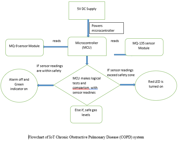
The Proposed Algorithm
The Circuit Diagram
The microcontroller unit (MCU) is designed using the Atmega328P-P microcontroller chip. Read more project tutorials using Atmega328P. The schematic diagram of this project is shown below.

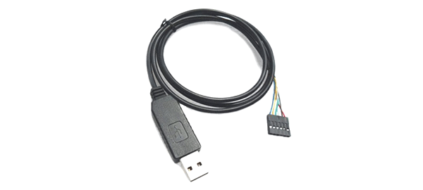
We will program it using an FTDI flex and Arduino IDE. The circuit diagram above sowed that we connected an external 16Mhz crystal with a pair of 22pF capacitors to suppress noise of MCU internal switching. To enable ISP programming; we connected 100nF capacitor to the RTS pinout for resetting when programing. We also connected another 100nF the power rails. This would make the programming go smoother.
The indicator LED is optional and can be added to know when the program was successfully uploaded.
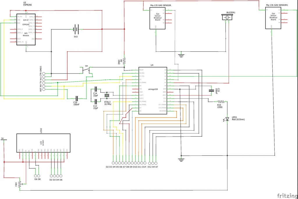
The two sensors are connected to he analog pins of the Atmega328P MCU standalone board. We also connected the a buzzer o notify us when the air contamination spikes high and unfit for breathing. The LCD module is connected using 4-bit configuration. The Register Select (RS) is connected to digital pin 7 (D7) of the Atmega328P MCU, Enable Pin (E) is connected to D8, while D4 through D7 of the LCD module is connected to D6 through D3 of the MCU IC.
The ESP8266-01 (ESP-01) WiFi module is is connected as a Station (STA) tot he MCU using software serial communication protocol. The Transmitter (Tx) pin of the ESp-01 is connected to the D9 of the MCU while the Receiver (Rx) pin is connected to D10 of the MCU. The reset pin of ESP-01 is connected to D11 while the Enable and Vcc pins are connected to 3.3V. The GND is connected to the GND power rail.
In testing and configuring the ESP-01 module. We connected the the Tx and Rx of the ESP-01 to the Tx and Rx of the MCU, then we changed the baud rate to 115200bps by opening the serial monitor on the Arduino IDE.
Arduino Source Code
We opened a blank sketch or Bare Minimum Sketch example and uploaded it to the System.
We type in the top pane: AT
The system would return: OK.
This would show that the system is communicating with he ESP-01 module. We type: AT+CWJAP=”USERNAME OF WIFI”,”PASSWORD OF WIFI” then hit enter.
This will display that it is connected to the WiFi and also show that it has been assigned an IP address.
After this; we can connect the ESP-01 as shown in the circuit diagram above and powered it up. It would reflect on our phones or router that we are using as WiFi access points.
Before uploading the code below to the design: we have to setup our Thingspeak channel. click here to read about setting a Thingspeak channel and account.
<!-- wp:code -->
<pre class="wp-block-code"><code>//Program Code for IoT Based Air Quality for COPD Patient
//include type of comm lib
#include <SoftwareSerial.h>
//type of comm pins connctn
SoftwareSerial EspSerial(9, 10);
//include the libs
#include <LiquidCrystal.h>
LiquidCrystal lcd(7, 8, 6, 5, 4, 3);
//include write key of thingspeak
String statusChWriteKey = "HREVVINHITJ179YP";
//define wia ESP-01 pin is connected
#define HARDWARE_RESET 11
//how many microseconds to write
long writeTimingSeconds = 17;
long startWriteTiming = 0;
long elapsedWriteTime = 0;
boolean error;
//declare the sensor input analog pins
const int MQ135_PIN = A0;
const int MQ136_PIN = A1;
int MQ135RL_VAlUE = 20;
int MQ136RL_VAlUE = 20;
float MQ135RO_CLEAN_AIR_FACTOR = 3.86;
float MQ136RO_CLEAN_AIR_FACTOR = 3.78;
#define buzzer 12
#define LED 13
int MQ135CALIBARAION_SAMPLE_TIMES = 50;
int MQ135CALIBRATION_SAMPLE_INTERVAL = 50;
int MQ135READ_SAMPLE_INTERVAL = 50;
int MQ135READ_SAMPLE_TIMES = 5;
int MQ136CALIBARAION_SAMPLE_TIMES = 50;
int MQ136CALIBRATION_SAMPLE_INTERVAL = 50;
int MQ136READ_SAMPLE_INTERVAL = 50;
int MQ136READ_SAMPLE_TIMES = 5;
#define GAS_CH4 0 //our aim is: mq-135 for CO2, Methane & NH3, mq-136 = H2S,
#define GAS_CO2 1
#define GAS_NH3 3
#define GAS_H2S 4
float CH4Curve[3] = {2.3,0.51,-0.39}; //pt.1 (log 200, log3.2), pt.2(log 10000, log.69) and slope m= (y2-y1)/(x2-x1) then we choose pt.1
float CO2Curve[3] = {2.3,0.72,-0.34}; //pt.1 (log200, log5.3), pt.2 (log10000, log1.5)
float NH3Curve[3] = {1.0,0.23,-0.15}; //pt.1 (log10, log1.7), pt.2(log100, log1.2)
float H2SCurve[3] = {1.3,0.11,-0.32}; //pt.1 (log20, log1.3) && pt.2(log100, log0.78)
float MQ135Ro = 10;
float MQ136Ro = 10;
long iPPM_CH4 = 0;
long iPPM_CO2 = 0;
long iPPM_NH3 = 0;
long iPPM_H2S = 0;
void setup() {
pinMode(MQ135_PIN, INPUT);
pinMode(MQ136_PIN, INPUT);
pinMode(buzzer, OUTPUT);
pinMode(HARDWARE_RESET, OUTPUT);
pinMode(LED, OUTPUT);
//begin serial comm
EspSerial.begin(9600);
Serial.begin(9600);
Serial.begin(115200);
//begin lcd
lcd.begin(20, 4);
//set the ESP-01 reset pin high and call reset functn
digitalWrite(HARDWARE_RESET, HIGH);
EspHardwareReset();
startWriteTiming = millis();
MQ135Ro = MQ135Calibration(MQ135_PIN);
MQ136Ro = MQ136Calibration(MQ136_PIN);
//print a welcome message
lcd.setCursor(0, 0);
lcd.print(" WELCOME TITO ");
lcd.setCursor(0, 1);
lcd.print(" INTERNET OF THINGS ");
lcd.setCursor(0, 2);
lcd.print("<<<< C.O.P.D >>>>");
lcd.setCursor(0, 3);
lcd.print("...PROJECT DESIGN...");
delay(3000);
lcd.clear();
lcd.setCursor(0, 0);
lcd.print("<<<PREPING SENSORS>>");
lcd.setCursor(0, 1);
lcd.print("PLEASE WAIT");
lcd.setCursor(11, 1);
for(int i = 0; i < 29; i++){
lcd.print(".");
delay(90);
}
}
void loop() {
iPPM_CH4 = MQ135GetGasPercentage(MQ135Read(MQ135_PIN)/MQ135Ro,GAS_CH4);
iPPM_CO2 = MQ135GetGasPercentage(MQ135Read(MQ135_PIN)/MQ135Ro,GAS_CO2);
iPPM_NH3 = MQ135GetGasPercentage(MQ135Read(MQ135_PIN)/MQ135Ro,GAS_NH3);
iPPM_H2S = MQ136GetGasPercentage(MQ136Read(MQ136_PIN)/MQ136Ro,GAS_H2S);
lcd.clear();
lcd.setCursor(0, 0);
lcd.print("CO2:");
lcd.setCursor(5, 0);
if(iPPM_CO2 < 100){
lcd.print(00);
}
lcd.print(iPPM_CO2);
lcd.print("ppm");
lcd.setCursor(0, 1);
lcd.print("H2S:");
lcd.setCursor(5, 1);
if(iPPM_H2S < 100){
lcd.print(00);
}
lcd.print(iPPM_H2S);
lcd.print("ppm");
lcd.setCursor(0, 2);
lcd.print("NH3:");
lcd.setCursor(5, 2);
if(iPPM_NH3 < 100){
lcd.print(00);
}
lcd.print(iPPM_NH3);
lcd.print("ppm");
lcd.setCursor(0, 3);
lcd.print("CH4:");
lcd.setCursor(5, 3);
if(iPPM_CH4 < 100){
lcd.print(00);
}
lcd.print(iPPM_CH4);
lcd.print("ppm");
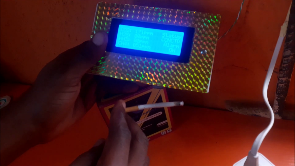
lcd.setCursor(14, 0);
lcd.print("Status");
lcd.setCursor(15, 2);
lcd.print("Alarm");
if((iPPM_CH4 < 40) || (iPPM_NH3 < 40) || (iPPM_H2S < 40) || (iPPM_CO2< 40)){
digitalWrite(buzzer, LOW);
lcd.setCursor(16, 3);
lcd.print("OFF");
}
if((iPPM_CH4 > 40) || (iPPM_NH3 > 40) || (iPPM_H2S > 40) || (iPPM_CO2 > 40)){
digitalWrite(buzzer, HIGH);
lcd.setCursor(16, 3);
lcd.print(" ON");
}
elapsedWriteTime = millis()-startWriteTiming;
if (elapsedWriteTime > (writeTimingSeconds*1000))
{
writeThingSpeak();
startWriteTiming = millis();
}
if (error==1) //Resend if transmission is not completed
{
lcd.setCursor(15, 1);
lcd.print("ERROR");
//lcd.setCursor(0, 1);
//lcd.print("INTERNET CONNCTN"); */
Serial.println(" <<<< ERROR >>>>");
delay (2000);
}
if (error==0) {
lcd.setCursor(14, 1);
lcd.print("CONCTD");
}
}
float MQ135ResistanceCalculation(int raw_adc){
return ( ((float)MQ135RL_VAlUE*(1023-raw_adc)/raw_adc));
}
float MQ136ResistanceCalculation(int raw_adc){
return ( ((float)MQ136RL_VAlUE*(1023-raw_adc)/raw_adc));
}
float MQ135Calibration(int mq_pin){
int i;
float val=0;
for (i=0;i<MQ135CALIBARAION_SAMPLE_TIMES;i++) {
val += MQ135ResistanceCalculation(analogRead(mq_pin));
Serial.println(val);
delay(MQ135CALIBRATION_SAMPLE_INTERVAL);
}
val = val/MQ135CALIBARAION_SAMPLE_TIMES;
val = val/MQ135RO_CLEAN_AIR_FACTOR;
return val;
}
float MQ136Calibration(int mq_pin)
{
int i;
float val=0;
for(i=0;i<MQ136CALIBARAION_SAMPLE_TIMES;i++) {
val += MQ136ResistanceCalculation(analogRead(mq_pin));
Serial.println(val);
delay(MQ136CALIBRATION_SAMPLE_INTERVAL);
}
val = val/MQ136CALIBARAION_SAMPLE_TIMES;
val = val/MQ136RO_CLEAN_AIR_FACTOR;
return val;
}
float MQ135Read(int mq_pin){
int i;
float rs=0;
for (i=0;i<MQ135READ_SAMPLE_TIMES;i++) {
rs += MQ135ResistanceCalculation(analogRead(mq_pin));
delay(MQ135READ_SAMPLE_INTERVAL);
}
rs = rs/MQ135READ_SAMPLE_TIMES;
return rs;
}
float MQ136Read(int mq_pin){
int i;
float rs=0;
for (i=0;i<MQ136READ_SAMPLE_TIMES;i++) {
rs += MQ136ResistanceCalculation(analogRead(mq_pin));
delay(MQ136READ_SAMPLE_INTERVAL);
}
rs = rs/MQ136READ_SAMPLE_TIMES;
return rs;
}
long MQ135GetGasPercentage(float rs_ro_ratio, int gas_id){
if ( gas_id == GAS_NH3 ) {
return MQ135GetPercentage(rs_ro_ratio,NH3Curve);
} else if ( gas_id == GAS_CO2 ) {
return MQ135GetPercentage(rs_ro_ratio,CO2Curve);
} else if ( gas_id == GAS_CH4 ) {
return MQ135GetPercentage(rs_ro_ratio,CH4Curve);
}
return 0;
}
long MQ136GetGasPercentage(float rs_ro_ratio, int gas_id){
if ( gas_id == GAS_H2S ) {
return MQ136GetPercentage(rs_ro_ratio,H2SCurve);
}
return 0;
}
long MQ135GetPercentage(float rs_ro_ratio, float *pcurve){
return (pow(10,( ((log(rs_ro_ratio)-pcurve[1])/pcurve[2]) + pcurve[0])));
}
long MQ136GetPercentage(float rs_ro_ratio, float *pcurve){
return (pow(10,( ((log(rs_ro_ratio)-pcurve[1])/pcurve[2]) + pcurve[0])));
}
/*this fxn writes to thingspeak*/
void writeThingSpeak(void){
startThingSpeakCmd();
// preparacao da string GET
String getStr = "GET /update?api_key=";
getStr += statusChWriteKey;
getStr +="&field1=";
getStr += String(iPPM_CO2);
getStr +="&field2=";
getStr += String(iPPM_H2S);
getStr +="&field3=";
getStr += String(iPPM_NH3);
getStr +="&field4=";
getStr += String(iPPM_CH4);
getStr += "\r\n\r\n";
sendThingSpeakGetCmd(getStr);
}
/* This fxn resets the ESP-01 */
void EspHardwareReset(void){
Serial.println("Reseting.......");
digitalWrite(HARDWARE_RESET, LOW);
delay(500);
digitalWrite(HARDWARE_RESET, HIGH);
delay(8000);//Tempo necessário para começar a ler
Serial.println("RESET");
}
/********* Start communication with ThingSpeak*************/
void startThingSpeakCmd(void){
EspSerial.flush();//limpa o buffer antes de começar a gravar
String cmd = "AT+CIPSTART=\"TCP\",\"";
cmd += "184.106.153.149"; // Endereco IP de api.thingspeak.com
cmd += "\",80";
EspSerial.println(cmd);
Serial.print("enviado ==> Start cmd: ");
Serial.println(cmd);
if(EspSerial.find("Error"))
{
Serial.println("AT+CIPSTART error");
return;
}
}
/********* send a GET cmd to ThingSpeak *************/
String sendThingSpeakGetCmd(String getStr){
String cmd = "AT+CIPSEND=";
cmd += String(getStr.length());
EspSerial.println(cmd);
Serial.print("enviado ==> lenght cmd: ");
Serial.println(cmd);
if(EspSerial.find((char *)">"))
{
EspSerial.print(getStr);
Serial.print("enviado ==> getStr: ");
Serial.println(getStr);
delay(500);//tempo para processar o GET, sem este delay apresenta busy no próximo comando
String messageBody = "";
while (EspSerial.available())
{
String line = EspSerial.readStringUntil('\n');
if (line.length() == 1)
{ //actual content starts after empty line (that has length 1)
messageBody = EspSerial.readStringUntil('\n');
}
}
Serial.print("MessageBody received: ");
Serial.println(messageBody);
return messageBody;
}
else
{
EspSerial.println("AT+CIPCLOSE"); // alert user
Serial.println("ESP8266 CIPSEND ERROR: RESENDING"); //Resend...
//spare = spare + 1;
error=1;
return "error";
}
}</code></pre>
<!-- /wp:code -->
The Thingspeak Write API has to be changed to the Thingspeak Write API for anyone who wants to use this source code. It is the String named StatusChWriteKey at code line 10. We used some calibration factors to adjust the gas sensor modules. Tis way we could use one sensor to take reading of different constituents of contaminants in air being breathed in by COPD patients.
We test our design and monitor the changes in the graphs on Thingspeak. A video demonstration is shown here below. Kindly like, subscribe and comment. Thank you.
Conclusion
Now we have shown you how we achieved this project, How to Design IoT Based Air Quality Monitoring For COPD Patients. Kindly let us know if you were able to build such similar project or a better version. We will be very glad to help you the best we we can. Let us know if you have any further questions in the comment section. You can also drop a suggestion too! To join the conversation, join our Telegram community, Telegram, Facebook page, Instagram and Twitter.

