Radio Identification (RFID) bus ticket system project help bus drivers to ensure proper fare collection from their passengers and cargo. It is the simplest seamless and hassle-free solution to transport fare payment. Let us take a look at how this was designed and programmed.
Materials/Components
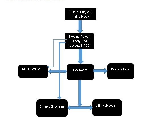
The materials needed for RFID based Bus-ticketing project are divided into four subsystems, namely; the external power supply unit (PSU), the programmable development board (microcontroller unit), the Liquid crystal Display (LCD) unit and the Radio frequency Identification.
- Header pins
- LCD connector wires
- 56OΩ precision resistor
- 10KΩ potentiometer (trimmer)
- 16 × 2 Liquid Crystal Display
- RFID- RC522 Module (with cards and tags)
- A reset push button.
- A 10KΩ pull-up resistor
- 22nF capacitors (2 pieces)
- 16MHz crystal oscillator (Newark part number 16C8140)
- Atmeg328P microcontroller
- Stripboard (perforated or perf board)
- LEDs
- Resistors
Radio Identification Bus Ticket System: The Circuit Diagram
The circuit diagram was first designed on the circuit designing IDE, Fritzing. It was also tested here using the source code since it supports a C/C++ extension called the Arduino programming language.
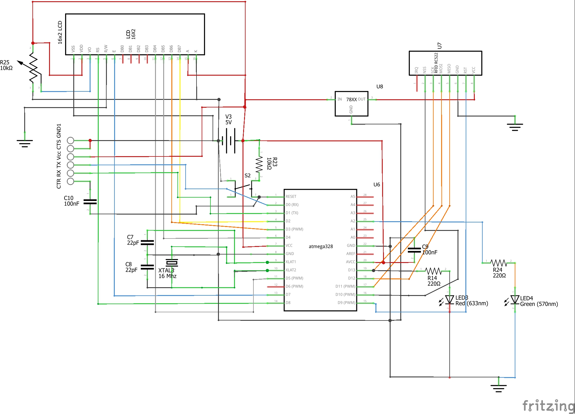
NB: Either Atmega168 or Atmega328P chip can work for this project. Just remember to select which chip you are using from Tools->Boards.
Bread-boarding Model phase
Next, the circuit diagram was brought down to the maker’s table and assembled using breadboards and jumper wires. It is breadboarded to test if it is working as specified. All errors encountered are checked and rechecked until the perfect solution is found.
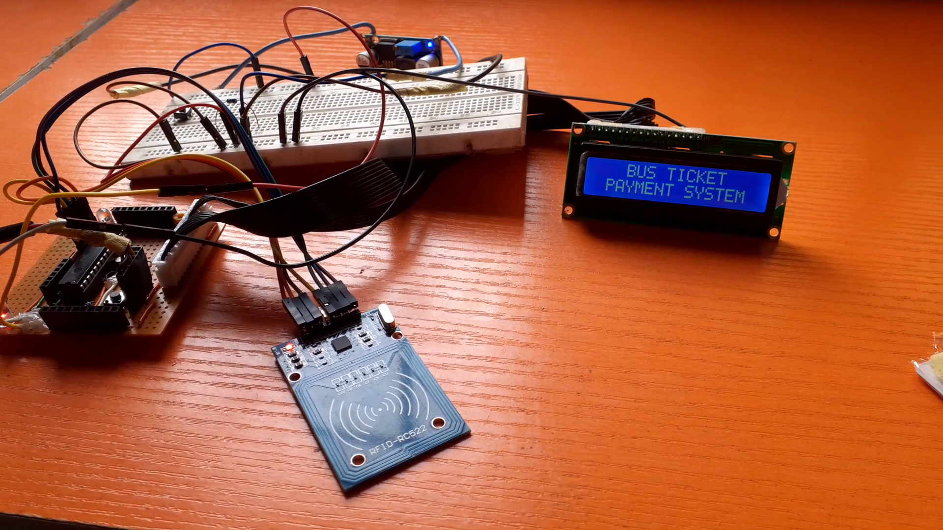
Soldering/Coupling the Radio Identification (RFID) Bus Ticket System Project
After the breadboard phase, we simply went to construction of the project design on a more permanent board by soldering the modules and components on strip board.
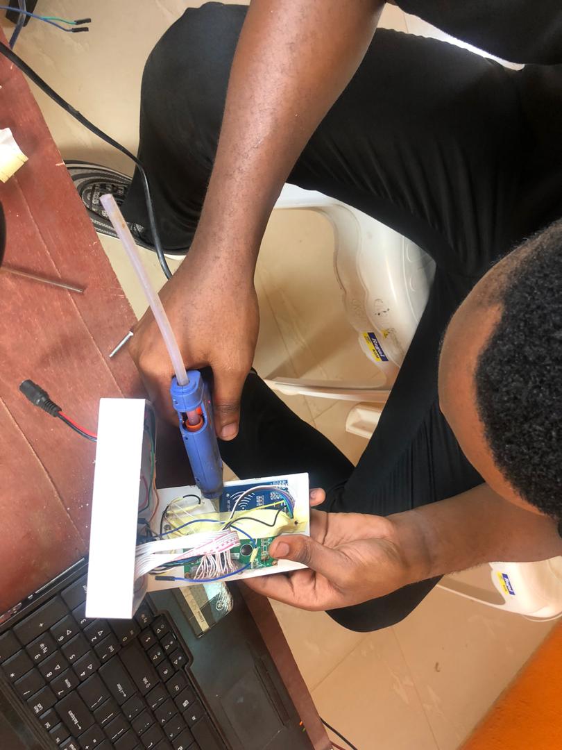
The casing of the project design was done with an adaptable box. The RFID reader was held onto the cover with a glue gun. The power comes from an external 5V 4A adapter that is connected via a power log.
Arduino Source Code (Sketch)
The sketch for this project design is given below. Feel free to modify to your taste,
//include the RFID libs
#include <SPI.h>
#include <MFRC522.h>
//include the LCD lib
#include <LiquidCrystal.h>
//declear the reset and SDA pins of RFID
#define SS_PIN 10
#define RST_PIN 9
// Create MFRC522 instance.
MFRC522 mfrc522(SS_PIN, RST_PIN); // Create MFRC522 instance.
//declear what LCD pins u are sending data
LiquidCrystal lcd(3, 2, 6, 4, 7, 5);
String pass1 = "CHIBUEZE";
String acct1 = "6A 2D 67 07";
String pass2 = "SMART";
String acct2 = "77 1F 73 63";
int balance1 = 1000;
int balance2 = 1000;
int rate = 200;
void setup()
{
Serial.begin(9600);
// Initiate SPI bus
SPI.begin();
// Initiate MFRC522
mfrc522.PCD_Init();
//begin the LCD
lcd.begin(16, 4);
//state your actuator pins
pinMode(A0, OUTPUT);
pinMode(A1, OUTPUT);
pinMode(A2, OUTPUT);
//display a welcome note
lcd.setCursor(0, 0);
lcd.print("WELCOME CHIBUEZE ");
delay(4000);
lcd.setCursor(0, 0);
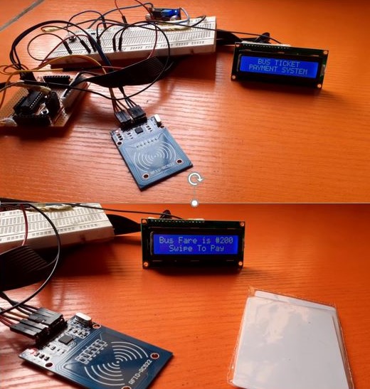
lcd.print(" BUS TICKET ");
lcd.setCursor(0, 1);
lcd.print(" PAYMENT SYSTEM ");
delay(2000);
lcd.clear();
//mfrc522.PCD_Init(); // Init MFRC522
lcd.setCursor(0, 2);
lcd.print(" ");
lcd.setCursor(0, 3);
lcd.print(" ");
}
void unregisted(){
tone(A0, 1000);
delay(500);
noTone(A0);
delay(500);
tone(A0, 1000);
delay(500);
noTone(A0);
delay(500);
tone(A0, 1000);
delay(500);
noTone(A0);
delay(500);
lcd.setCursor(0, 0);
lcd.print(" UNREGISTERED ");
delay(2000);
lcd.setCursor(0, 1);
lcd.print("PLS GET A VALID CARD");
for (int positionCounter = 0; positionCounter < 43; positionCounter++) {
// scroll one position left:
lcd.scrollDisplayLeft();
// wait a bit:
delay(150);
}
//lcd.clear();
}
void loop() {
//turn off the actuators
digitalWrite(A0, LOW);
analogWrite(A1, 0);
analogWrite(A2, 0);
lcd.setCursor(0, 0);
lcd.print("Bus Fare is #");
lcd.println(rate);
lcd.println(" ");
lcd.setCursor(0, 1);
lcd.print(" Swipe To Pay ");
// Look for new cards
if ( ! mfrc522.PICC_IsNewCardPresent())
{
return;
}
// Select one of the cards
if ( ! mfrc522.PICC_ReadCardSerial())
{
return;
}
//Show UID on serial monitor
Serial.print("UID tag :");
String content= "";
byte letter;
for (byte i = 0; i < mfrc522.uid.size; i++)
{
Serial.print(mfrc522.uid.uidByte[i] < 0x10 ? " 0" : " ");
Serial.print(mfrc522.uid.uidByte[i], HEX);
content.concat(String(mfrc522.uid.uidByte[i] < 0x10 ? " 0" : " "));
content.concat(String(mfrc522.uid.uidByte[i], HEX));
}
Serial.println();
Serial.print("Message : ");
content.toUpperCase();
//this is where u put the UID of the card that you want to give access
if (content.substring(1) == "6A 2D 67 07") {
analogWrite(A2, 255);
delay(250);
analogWrite(A2, 0);
delay(250);
analogWrite(A2, 255);
if (balance1 >= rate){
balance1 -= rate;
lcd.setCursor(0, 0);
lcd.print(" Hi CHIBUEZE ");
lcd.setCursor(0, 1);
lcd.print("___Payment O.K___ ");
}
else{
lcd.setCursor(0, 0);
lcd.print(" Sorry CHIBUEZE ");
lcd.setCursor(0, 1);
lcd.print("Insuficient Fund");
}
delay(4000);
lcd.setCursor(0, 1);
lcd.print("_Balance is #");
lcd.println(balance1);
lcd.println(". .");
delay(4000);
return;
}
if (content.substring(1) == "77 1F 73 63") {
analogWrite(A2, 255);
delay(250);
analogWrite(A2, 0);
delay(250);
analogWrite(A2, 255);
if (balance2 >= rate){
balance2 -= rate;
lcd.setCursor(0, 0);
lcd.print(" Hi SMART ");
lcd.setCursor(0, 1);
lcd.print("___Payment O.K___ ");
}
else{
lcd.setCursor(0, 0);
lcd.print(" Sorry SMART ");
lcd.setCursor(0, 1);
lcd.print("Insuficient Fund");
}
delay(4000);
lcd.setCursor(0, 1);
lcd.print("_Balance is #");
lcd.println(balance2);
lcd.println(". .");
delay(4000);
return;
}
else{
lcd.clear();
analogWrite(A1, 255);
delay(250);
analogWrite(A1, 0);
delay(250);
analogWrite(A1, 255);
unregisted();
}
lcd.clear();
}
Source Code Explanation
From line 2 through 6, we included the libraries we needed for the design. We defined where we connected the Slave Select (SS) and reset (RST) pins on the standalone board. From code line 19 through 25 we declared String type variables where we assigned the name of the account holder in the database, the amount in each account, and the deduction fare rate of the bus transit system. In the setup function, we began the serial peripheral interface communication, which is very necessary for the RFID reader, and also the MFRC was initiated. We printed out a welcome note and then set our outputs for the buzzer and two LEDs using the analog I/O pins. An additional function; ‘unregistered’, was created to loop invalid response message displays and pulsate the buzzer when a user or passenger tries to play funny by using a card or ring tag that doesn’t have money in it. We further used if and else statements to check when a user has maxed out his or her card.
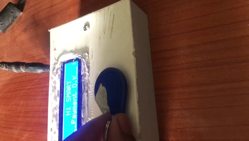
For video demonstration, you can click on the YouTube clip below and give us a thumbs up.
Conclusion
Now we have shown you how we achieved this project, radio identification bus ticket system. Kindly let us know if you were able to build such similar project or a better version. We will be very glad to help you the best we we can. Let us know if you have any further questions in the comment section. You can also drop a suggestion too! To join the conversation, join our Telegram community, Telegram, Facebook page, Instagram and Twitter.

