Watch the YouTube video here to get the workings of the Project design first hand experience.
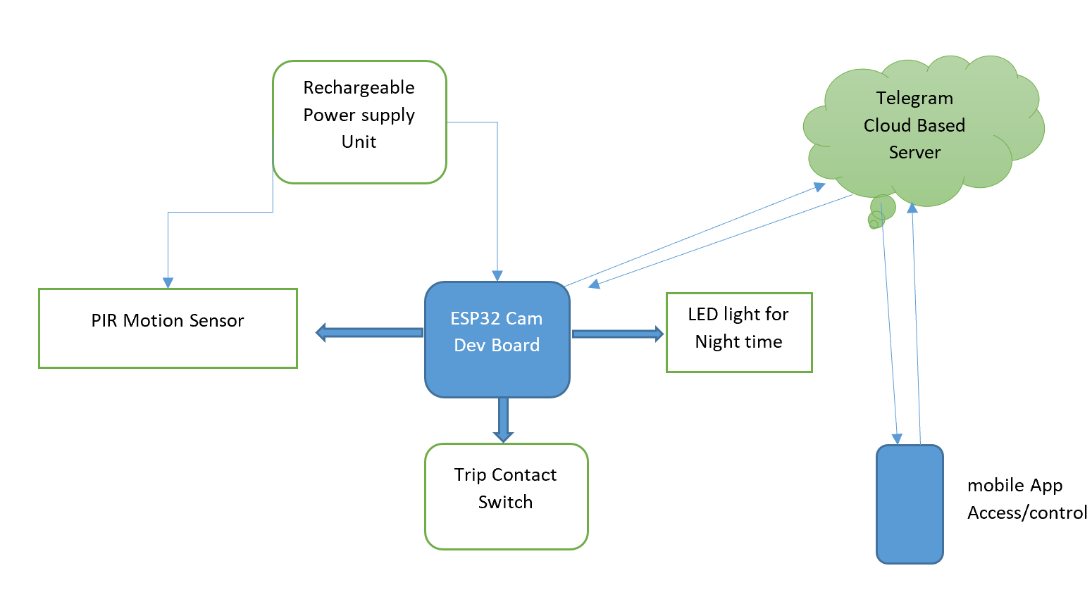
The block diagram above illustrates the processes involved in the IoT manhole lid surveillance project design. The project design is about detecting illegal and unauthorized entry into manholes. The design is attached at the end of the manhole, pointed and rigged to detect unapproved motion at the manhole entrance. Once armed, any illegal entry notify the admin via call, then a text message and telegram chat that contains the pictures of the person entering the manhole.

The manhole lid surveillance project design uses Telegram as its IoT platform, making use of a Telegram bot, to notify the admin when there is activity at the manhole point without proper clearance. As well as sending snapshots of the activities happening at the entrance point. Since we can’t go poking around in actual manholes to implement this, we used a bucket to model a prototype of this to show how it works.
Components and Materials Needed for Manhole Lid Surveillance Project
| ITEM DESCRIPTION | QUANTITY |
| LiPo CHARGING MODULE | 1 |
| ESP32 CAM BOARD | 1 |
| LEDs | 1 |
| RESISTORS | 2 |
| LiPO BATTERY | 1 |
| CONNECTING WIRES | 1 Yard |
| CASING | 1 |
| VERO BOARD | 1 |
| SOLDER | 1 |
| SOLDERING IRON | 1 |
| PIEZO BUZZER | 1 |
| MISCELLANEOUS |
The system design has a development (Dev) board from the Expressif company; namely, the ESP32 Cam Dev board. The development board ESP32 Cam is used to take real time photographs on the mobile app using its onboard OV2460 Camera module attached to it and also offers users access to Arm and Unarm the device remotely from anywhere in the world. The Motion sensor module was connected to the Dev. Board so was the contact trip system such that the former would detect motion and send a captured picture of such motion while the lid contact trip mechanism would alert the user once the lip was opened during its Armed state with the backed up photograph captured during the time of someone opening the lip.
Read More Posts Like These
- Arduino Smart Light Control Benefits
- Arduino Smart Light Control Project Ideas
- Design An RFID-Based Access Control with Disinfectant Booth
- 3d Atom Model Project Ideas
Schematic Diagram Manhole Lid Surveillance Project
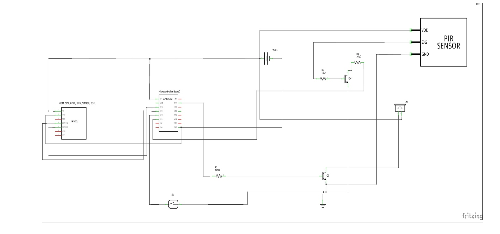
Explanation of Schematic Diagram
The circuit diagram shown above uses the the GSM module SIM800L EVB type connected the development board ESP32 Cam in serial communication protocol. The Rx (receiver pin) of the SIM800L is connected to IO13 pin of the ESP32 cam while the TX (Transmitter pin) of the SIM800L is connected to IO12 of the EPS32 Cam dev board. The GSM module can be powered by a 5V DC power rail so can the ESP32 Cam board. All connections are made in parallel.
To deter off burglars or illegal entry into the manhole, we used a buzzer to sound an alarm when an illegal entry is made. This is connected as common emitter follower to the NPN transistor shown above in the schematic diagram. We kept the other NPN transistor connected to the IO15 pin of the ESP32 Cam (this pin was programed to be active LOW), so that it can trip or send a signal of motion is detected by the PIR sensor. The reed switch is connected to to the top or lid of the modelled manhole so that it can create a trigger when the lip is removed illegally.
Assembling The Project Design
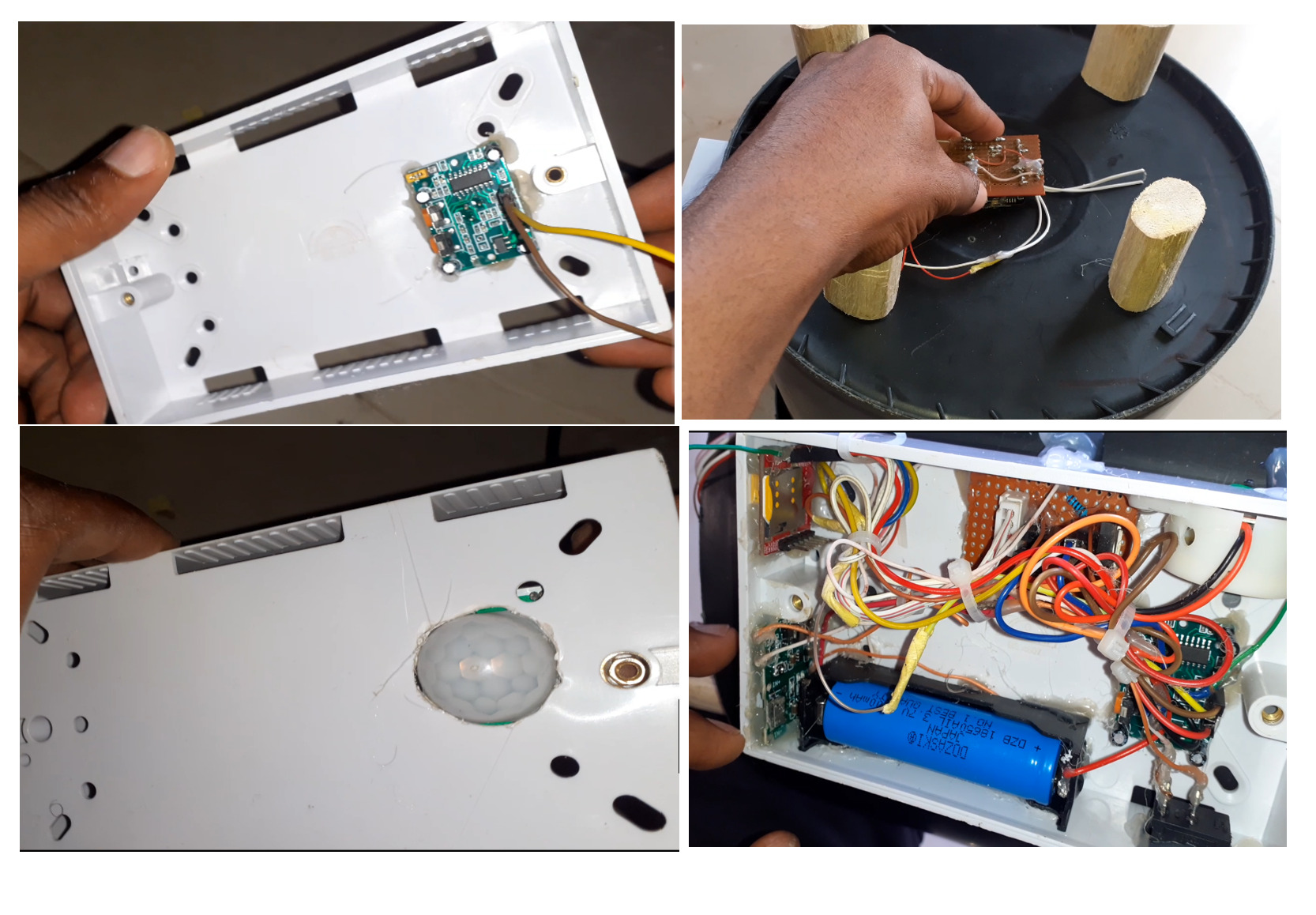
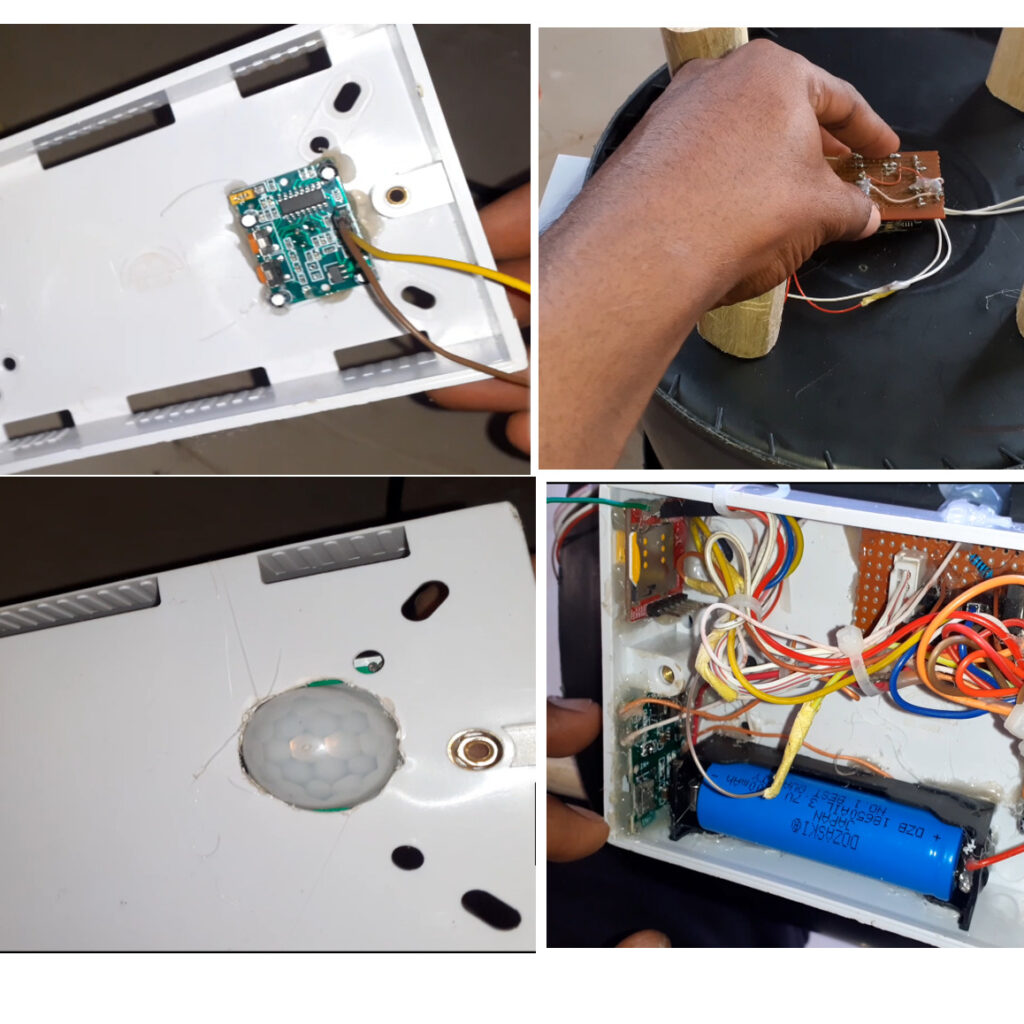
We used a 3 by 6 inch box, and cut a hole in it and we placed the PIR motion sensor. We also cut out a hole by the side of the model manhole where we can affix this bulge of the PIR sensor. The other components were connected according to the schematic diagram.
We placed the camera at the bottom of the bucket where it can have direct view of the person opening the lid and entering the manhole. The design is also powered by a rechargeable LiPo battery, which means it can run on its own.
Programming The Manhole Lid Surveillance Project
#include <Arduino.h>
#include <WiFi.h>
#include <WiFiClientSecure.h>
#include "soc/soc.h"
#include "soc/rtc_cntl_reg.h"
#include "esp_camera.h"
#include <UniversalTelegramBot.h>
#include <ArduinoJson.h>

const char* ssid = "AncII";
const char* password = "eureka26";

// Initialize Telegram BOT
String BOTtoken = "5372751881:AAHV3RKHUXZFYgYT4k7h25XdQMlR1CR1ruI";  // your Bot Token (Get from Botfather)

String CHAT_ID = "1141844942";

bool sendPhoto = false;
bool engaged = false;
bool flashState = 0;

WiFiClientSecure clientTCP;
UniversalTelegramBot bot(BOTtoken, clientTCP);

#define FLASH_LED_PIN 4
#define motionSensor 14
#define lidCoverSensor 15
#define buzzer 16
//coonect GSM Module RX pin to ESP32 Pin 12
//connect GSM Module TX pin to ESP32 Pin 13
#define rxPin 12
#define txPin 13
#define BAUD_RATE 115200
HardwareSerial sim800(1);

int readPirSensor, readReedSensor;


//Checks for new messages every 1 second.
int botRequestDelay = 1000;
unsigned long lastTimeBotRan;

//CAMERA_MODEL_AI_THINKER
#define PWDN_GPIO_NUM     32
#define RESET_GPIO_NUM    -1
#define XCLK_GPIO_NUM      0
#define SIOD_GPIO_NUM     26
#define SIOC_GPIO_NUM     27

#define Y9_GPIO_NUM       35
#define Y8_GPIO_NUM       34
#define Y7_GPIO_NUM       39
#define Y6_GPIO_NUM       36
#define Y5_GPIO_NUM       21
#define Y4_GPIO_NUM       19
#define Y3_GPIO_NUM       18
#define Y2_GPIO_NUM        5
#define VSYNC_GPIO_NUM    25
#define HREF_GPIO_NUM     23
#define PCLK_GPIO_NUM     22


void configInitCamera(){
  camera_config_t config;
  config.ledc_channel = LEDC_CHANNEL_0;
  config.ledc_timer = LEDC_TIMER_0;
  config.pin_d0 = Y2_GPIO_NUM;
  config.pin_d1 = Y3_GPIO_NUM;
  config.pin_d2 = Y4_GPIO_NUM;
  config.pin_d3 = Y5_GPIO_NUM;
  config.pin_d4 = Y6_GPIO_NUM;
  config.pin_d5 = Y7_GPIO_NUM;
  config.pin_d6 = Y8_GPIO_NUM;
  config.pin_d7 = Y9_GPIO_NUM;
  config.pin_xclk = XCLK_GPIO_NUM;
  config.pin_pclk = PCLK_GPIO_NUM;
  config.pin_vsync = VSYNC_GPIO_NUM;
  config.pin_href = HREF_GPIO_NUM;
  config.pin_sscb_sda = SIOD_GPIO_NUM;
  config.pin_sscb_scl = SIOC_GPIO_NUM;
  config.pin_pwdn = PWDN_GPIO_NUM;
  config.pin_reset = RESET_GPIO_NUM;
  config.xclk_freq_hz = 20000000;
  config.pixel_format = PIXFORMAT_JPEG;

  //init with high specs to pre-allocate larger buffers
  if(psramFound()){
    config.frame_size = FRAMESIZE_UXGA;
    config.jpeg_quality = 10;  //0-63 lower number means higher quality
    config.fb_count = 2;
  } else {
    config.frame_size = FRAMESIZE_SVGA;
    config.jpeg_quality = 12;  //0-63 lower number means higher quality
    config.fb_count = 1;
  }

  // camera init
  esp_err_t err = esp_camera_init(&config);
  if (err != ESP_OK) {
    Serial.printf("Camera init failed with error 0x%x", err);
    delay(1000);
    ESP.restart();
  }

  // Drop down frame size for higher initial frame rate
  sensor_t * s = esp_camera_sensor_get();
  s->set_framesize(s, FRAMESIZE_CIF);  //UXGA|SXGA|XGA|SVGA|VGA|CIF|QVGA|HQVGA|QQVGA
}


bool pirSensor() {
  //read the pushbutton value into a variable
   readPirSensor = digitalRead(motionSensor);
//   Serial.print("Motion Sensor: ");
//       Serial.println(readPirSensor);
return readPirSensor;
}

bool lidCover() {
  //read the pushbutton value into a variable
   readReedSensor = digitalRead(lidCoverSensor);
//   Serial.print("lid cover: ");
//       Serial.println(readReedSensor);
return readReedSensor;

}


void handleNewMessages(int numNewMessages) {
  Serial.print("Handle New Messages: ");
  Serial.println(numNewMessages);
for (int i = 0; i < numNewMessages; i++) {
    String chat_id = String(bot.messages[i].chat_id);
    if (chat_id != CHAT_ID){
      bot.sendMessage(chat_id, "Unauthorized user", "");
      continue;
    }

    // Print the received message
    String text = bot.messages[i].text;
    Serial.println(text);

    String from_name = bot.messages[i].from_name;
    if (text == "/start") {
      String welcome = "Welcome , " + from_name + "\n";
      welcome += "Use the following commands to interact with the ESP32-CAM \n";
      welcome += "/arm : to arm the device\n";
      welcome += "/disarm : to disarm the device\n";
      welcome += "/photo : takes a new photo\n";
      welcome += "/flashLightOn : turn on flash \n";
      welcome += "/flashLightOff : turn off flash \n";
      bot.sendMessage(CHAT_ID, welcome, "");
    }

    if(text == "/arm"){
       engaged = true;
      Serial.println("system armed");
      bot.sendMessage(CHAT_ID, "System is armed", "");

    }

    if(text == "/disarm"){
       engaged = false;
      Serial.println("system disarmed");
      bot.sendMessage(CHAT_ID, "System is disarmed", "");
    }

    if (text == "/flashLightOn") {
      digitalWrite(FLASH_LED_PIN, HIGH);
      Serial.println("flash LED on");
      String flashStatus = "Sir " + from_name + "\n";
      flashStatus += "flash of ESP32-CAM turned on \n";
      bot.sendMessage(CHAT_ID, flashStatus, "");
    }

    if (text == "/flashLightOff") {
      digitalWrite(FLASH_LED_PIN, LOW);
      Serial.println("flash LED off");
      String flashStatus = "Sir " + from_name + "\n";
      flashStatus += "flash of ESP32-CAM turned off \n";
      bot.sendMessage(CHAT_ID, flashStatus, "");
    }

    if (text == "/photo") {
            sendPhoto = true;
      Serial.println("New photo request");
    }
  }
}


String sendPhotoTelegram() {
  const char* myDomain = "api.telegram.org";
  String getAll = "";
  String getBody = "";

  camera_fb_t * fb = NULL;
  fb = esp_camera_fb_get();
  if(!fb) {
    Serial.println("Camera capture failed");
    delay(1000);
    ESP.restart();
    return "Camera capture failed";
  }

  Serial.println("Connect to " + String(myDomain));


  if (clientTCP.connect(myDomain, 443)) {
    Serial.println("Connection successful");

    String head = "--Anc\r\nContent-Disposition: form-data; name=\"chat_id\"; \r\n\r\n" + CHAT_ID + "\r\n--Anc\r\nContent-Disposition: form-data; name=\"photo\"; filename=\"esp32-cam.jpg\"\r\nContent-Type: image/jpeg\r\n\r\n";
    String tail = "\r\n--Anc--\r\n";

    uint16_t imageLen = fb->len;
    uint16_t extraLen = head.length() + tail.length();
    uint16_t totalLen = imageLen + extraLen;

    clientTCP.println("POST /bot"+BOTtoken+"/sendPhoto HTTP/1.1");
    clientTCP.println("Host: " + String(myDomain));
    clientTCP.println("Content-Length: " + String(totalLen));
    clientTCP.println("Content-Type: multipart/form-data; boundary=Anc");
    clientTCP.println();
    clientTCP.print(head);

    uint8_t *fbBuf = fb->buf;
    size_t fbLen = fb->len;
    for (size_t n=0;n<fbLen;n=n+1024) {
      if (n+1024<fbLen) {
        clientTCP.write(fbBuf, 1024);
        fbBuf += 1024;
      }
      else if (fbLen%1024>0) {
        size_t remainder = fbLen%1024;
        clientTCP.write(fbBuf, remainder);
      }
    }

    clientTCP.print(tail);

    esp_camera_fb_return(fb);

    int waitTime = 10000;   // timeout 10 seconds
    long startTimer = millis();
    boolean state = false;

    while ((startTimer + waitTime) > millis()){
      Serial.print(".");
      delay(100);
      while (clientTCP.available()) {
        char c = clientTCP.read();
        if (state==true) getBody += String(c);
        if (c == '\n') {
          if (getAll.length()==0) state=true;
          getAll = "";
        }
        else if (c != '\r')
          getAll += String(c);
        startTimer = millis();
      }
      if (getBody.length()>0) break;
    }
    clientTCP.stop();
    Serial.println(getBody);
  }
  else {
    getBody="Connected to api.telegram.org failed.";
    Serial.println("Connected to api.telegram.org failed.");
  }
  return getBody;
}

void setup(){
  WRITE_PERI_REG(RTC_CNTL_BROWN_OUT_REG, 0);
  // Init Serial Monitor
  Serial.begin(115200);
  sim800.begin(BAUD_RATE, SERIAL_8N1, rxPin, txPin);


  // Set LED Flash as output
  pinMode(FLASH_LED_PIN, OUTPUT);
  pinMode(motionSensor, INPUT_PULLUP);
  pinMode(lidCoverSensor, INPUT_PULLUP);
  pinMode(buzzer, OUTPUT);
  digitalWrite(buzzer, LOW);

  // Config and init the camera
  configInitCamera();

  // Connect to Wi-Fi
  WiFi.mode(WIFI_STA);
  Serial.println();
  Serial.print("Connecting to ");
  Serial.println(ssid);
  WiFi.begin(ssid, password);
  clientTCP.setCACert(TELEGRAM_CERTIFICATE_ROOT); // Add root certificate for api.telegram.org
  while (WiFi.status() != WL_CONNECTED) {
    Serial.print(".");
    delay(500);
  }
  Serial.println();
  Serial.print("ESP32-CAM IP Address: ");
  Serial.println(WiFi.localIP());

}


void sendSMS(){
       sim800.println("AT"); //Once the handshake test is successful, it will back to OK
  updateSerial();

  sim800.println("AT+CMGF=1"); // Configuring TEXT mode
  updateSerial();
  sim800.println("AT+CMGS=\"+2349024795241\"\r\n");//change ZZ with country code and xxxxxxxxxxx with phone number to sms
  updateSerial();
  sim800.print("Motion/Lid Open Detection Alert"); //text content
  updateSerial();
  sim800.write(26);
}


void makeCall(){
  sim800.println("AT"); //Once the handshake test is successful, i t will back to OK
  updateSerial();

  sim800.println("ATD+ +2349024795241;"); //  change ZZ with country code and xxxxxxxxxxx with phone number to dial
  updateSerial();
  delay(10000); // wait for 20 seconds...
  sim800.println("ATH"); //hang up
  updateSerial();
}


void alarm(){
  digitalWrite(buzzer, HIGH);
  delay(6000);
  digitalWrite(buzzer, LOW);
}


void updateSerial(){
  delay(500);
  while (Serial.available()) {
    sim800.print(Serial.read());//Forward what Serial received to Software Serial Port
  }
  while(sim800.available())
  {
    Serial.write(sim800.read());//Forward what Software Serial received to Serial Port
  }
}


void loop() {
  pirSensor();
lidCover();

while(Serial.available())  {
  sim800.println(Serial.readString());
}

//
//Serial.print("Engaged state: ");
//Serial.print(engaged);
//Serial.print("reed sensor: ");
//Serial.println(readReedSensor);
//delay(500);

if((engaged == 1) && (readPirSensor == 0)){
Serial.println("Preparing photo");
 bot.sendMessage(CHAT_ID, "Motion Detected \nHere is Picture", "");
    sendPhotoTelegram();
    sendPhoto = false;
    alarm();
    delay(2000);
    makeCall();
    sendSMS();
}

if((engaged == 1) && (readReedSensor == 1)){
Serial.println("Preparing photo");
 bot.sendMessage(CHAT_ID, "Manhole Lid Opened \nHere is Picture", "");
    sendPhotoTelegram();
    sendPhoto = false;
    alarm();
    delay(2000);
    makeCall();
    sendSMS();
}

   if (sendPhoto) {
    Serial.println("Preparing photo");
    sendPhotoTelegram();
    sendPhoto = false;
  }


  if (millis() > lastTimeBotRan + botRequestDelay)  {
    int numNewMessages = bot.getUpdates(bot.last_message_received + 1);
    while (numNewMessages) {
      Serial.println("got response");
      handleNewMessages(numNewMessages);
      numNewMessages = bot.getUpdates(bot.last_message_received + 1);
    }
    lastTimeBotRan = millis();
  }
}
Explanation of The Code
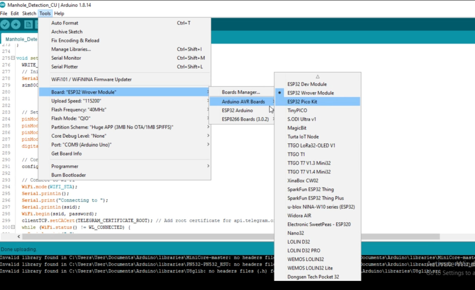
The source code is pretty simple and has comment lines to explain what each line of code does. On ce you copy and paste the code above, go to tools, select your board under ESP32 Arduino, select ESP32 Wrover Module, compile and upload the code after that.
Creating the Telegram Chat Bot For the Project
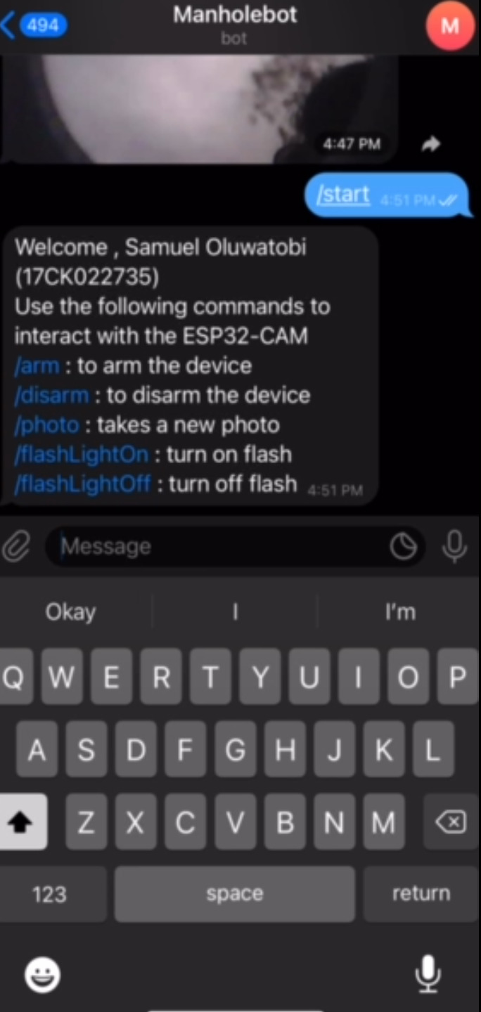
The Telegram bot was created using Botfather. Read more on how to create such bot for IoT purpose here. Once the bot is created, we can send specific commands to it to get a remote control and response. As shown above, when we send “start” the bot replies with specific commands of what next to do. You can arm, disarm, take a picture, turn on the light when it is dark or turn it off.
Conclusion
We have designed, programmed and constructed an IoT based manhole lid detection with surveillance camera project that work with Telegram bot. When armed, it has the capacity to auto-detect intrusion at the manhole and notify the admin with a call or SMS that illegal entry was made. And when the admin, opens his app, he can see the pictures of the person who gained illegal entry.
FAQs
IoT Based Manhole Lid Detection PPT
An IoT-based manhole lid detection PPT would typically cover the following topics:
- Introduction to IoT and its applications in smart cities
- Problem statement: Manhole lid theft and its consequences
- Proposed solution: IoT-based manhole lid detection system
- System architecture and components: Sensors, microcontrollers, communication modules, cloud platform
- Working principle: Sensor detects lid removal, microcontroller triggers alarm and sends notification to cloud platform
- Benefits of IoT-based manhole lid detection: Improved safety, reduced maintenance costs, enhanced data collection and analysis
- Applications beyond manhole lid detection: Smart streetlights, waste management, environmental monitoring
Iot Based Manhole Lid Detection PDF
An IoT-based manhole lid detection PDF would provide more in-depth information on the topic, including:
- Detailed technical specifications of the system components
- Implementation details, including software development and hardware integration
- Case studies of successful IoT-based manhole lid detection deployments
- Cost analysis and economic benefits
- Future directions and research opportunities
Iot based manhole lid detection cost
The cost of an IoT-based manhole lid detection system varies depending on the specific components, features, and scale of deployment. However, a typical system for a small municipality might cost around $50-$100 per manhole lid.
IoT Based Manhole Lid Detection Advantages
The advantages of IoT-based manhole lid detection include:
- Real-time monitoring and theft prevention
- Reduced maintenance costs and improved safety
- Enhanced data collection and analysis for city planning
- Improved communication and coordination among city departments
- Potential for integration with other smart city solutions
IoT Based Smart Energy Meter Monitoring With Theft Detection
IoT-based smart energy meter monitoring with theft detection can help utilities address energy theft and optimize energy consumption. Smart meters can collect real-time data on energy usage, identify anomalies, and detect tampering. This data can be used to identify potential theft cases and alert authorities. Additionally, smart meters can enable dynamic pricing and demand response programs to encourage energy conservation.
Manhole Monitoring System IEEE
The IEEE has published various papers on manhole monitoring systems, including:
- “A Wireless Sensor Network for Manhole Monitoring and Fault Detection” by H. Li et al. (2010)
- “Design and Implementation of an IoT-based Manhole Lid Monitoring System” by J. Liu et al. (2017)
- “A Smart Manhole Monitoring System for Urban Infrastructure Management” by Y. Zhang et al. (2018)
What is Automatic Manhole Cover
Automatic manhole covers are designed to open and close automatically in response to traffic conditions or sensor readings. This can help to improve safety and reduce maintenance costs.
IoT Based Projects
There are many other IoT-based projects that can be implemented in smart cities, such as:
- Smart parking systems
- Intelligent traffic management systems
- Environmental monitoring systems
- Waste management systems
- Public safety and surveillance systems

