In a world where renewable energy and smart technology are taking center stage, combining these two innovations into a DIY project is both fascinating and practical. Imagine a streetlight powered by footsteps – harnessing human energy to light up the night while sending data to an IoT platform for real-time monitoring. Sounds exciting? Let’s dive into how you can build this cutting-edge project, a DIY Smart Streetlight Powered by Footstep Energy.
What Is a Smart Streetlight Powered by Footstep Energy?

A smart streetlight powered by footstep energy is a sustainable lighting system that uses energy generated from footfalls to charge a battery, which powers the streetlight. It combines motion detection, light-sensing capabilities, and IoT integration to create a highly efficient and futuristic lighting solution.
How Does It Work?

This project relies on three main components:
- Footstep Energy Generator: Converts kinetic energy from footsteps into electrical energy.
- Arduino Microcontroller: Acts as the brain of the system, controlling the motion sensor, LDR, and ESP-01 module.
- ESP-01 Module: Sends real-time data about the battery voltage and charging status to an IoT platform.
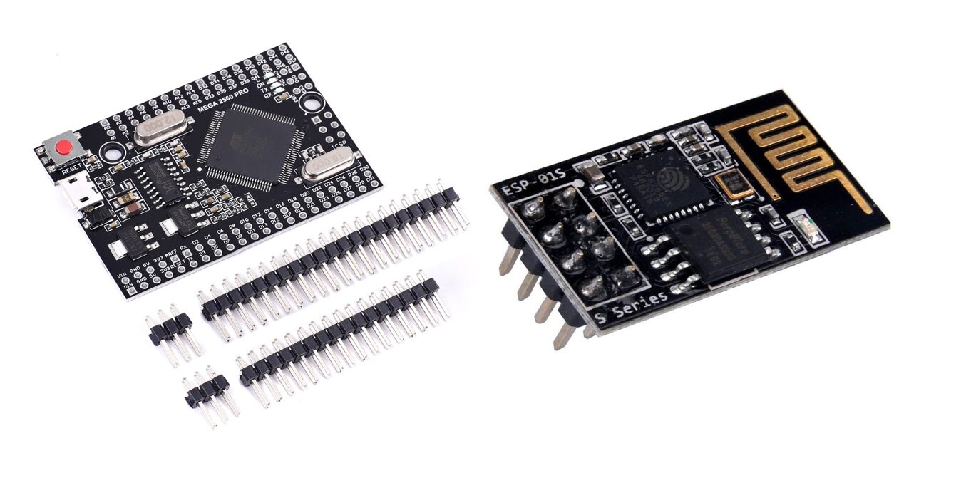
These components are very vital for the project design itself. We used the ESP-01 module to give the design an internet access to communicate with the IoT platform.
Key Features of the DIY Smart Streetlight
- Motion-Activated Brightness: A motion sensor ensures the light only brightens when someone is nearby, conserving energy.
- Day/Night Detection: An LDR (Light Dependent Resistor) detects ambient light levels, activating the streetlight only at night.
- IoT Monitoring: The ESP-01 module uploads battery voltage and charging status to an IoT platform for remote monitoring.
- Renewable Energy Source: A footstep energy generator charges the battery, reducing dependency on traditional power sources.
Components Required
Before you start building, gather the following components:
Core Electronics
- Arduino Mega (or any compatible microcontroller)
- ESP-01 Wi-Fi Module
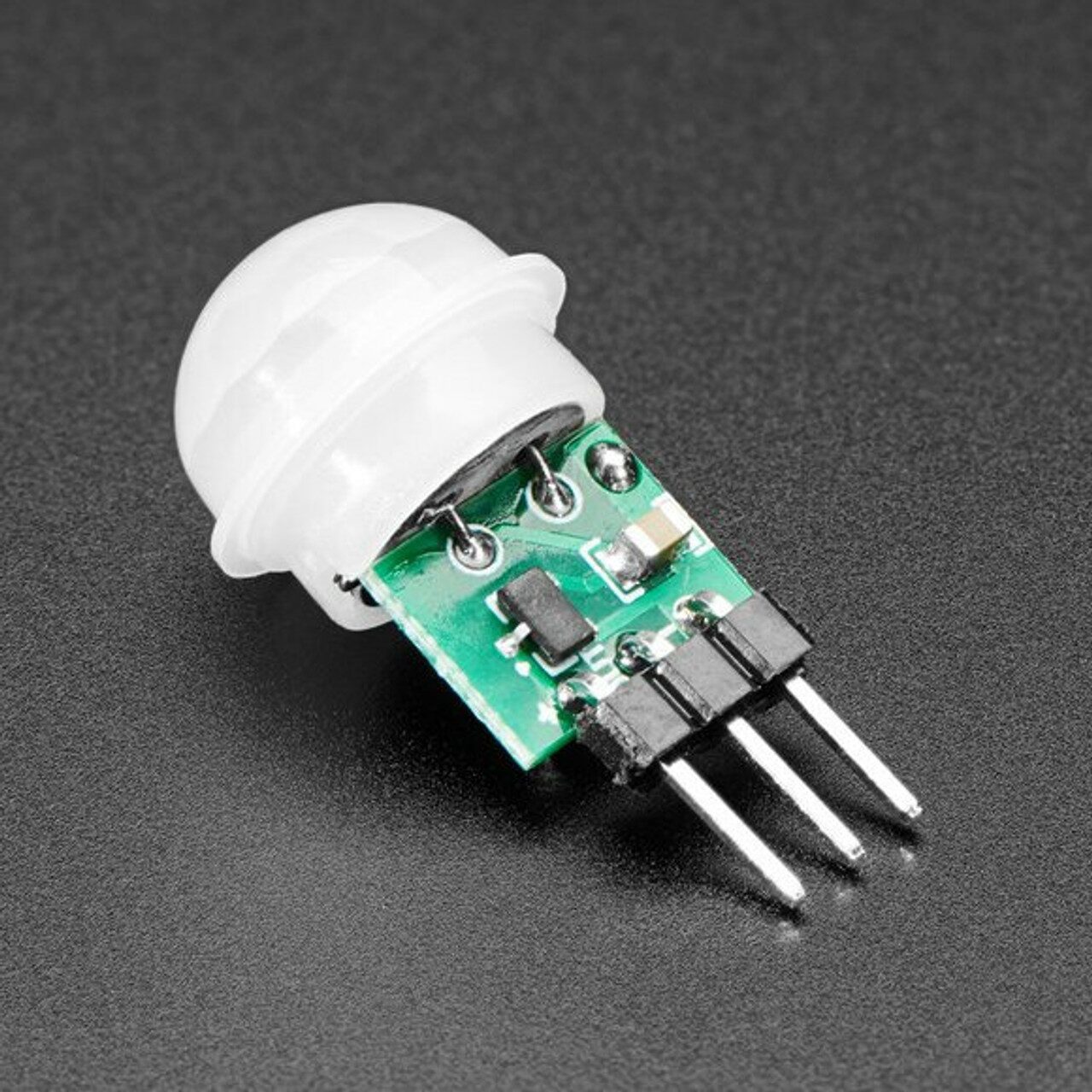
- PIR Motion Sensor
- LDR (Light Dependent Resistor)
- Rechargeable Battery (12V recommended)
- Battery Charging Circuit
- Footstep Energy Generator
Additional Components
- Resistors (1kΩ, 10kΩ)
- Capacitors
- Diodes (1N4007 or similar)
- Voltage Regulator (e.g., LM7805)
- LED red and green
- Connecting Wires
- Veroboard or PCB
Read Also: How to Cope with Breakups: Moving On After a Relationship Ends
Step-by-Step Guide to Building the Smart Streetlight
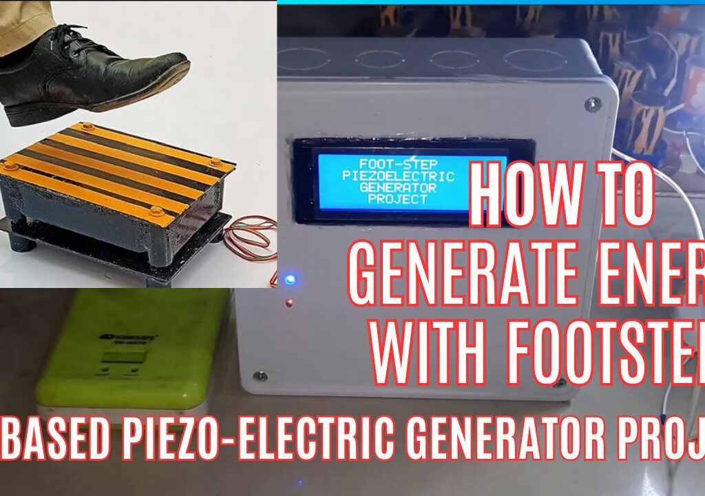
Step 1: Setting Up the Footstep Energy Generator
The footstep energy generator is a piezoelectric system that generates electricity when pressure is applied. The first thing we do is to assemble and align the PZT materials on a flat wood, this is done judiciously. After carefully placing these transducers on the flat board, we can move onto the next step. While in the process of laying down the PZT sensors, we have to align them in a way it will be most convenient to connect them in a series connection as shown in the schematic diagram. Once we have achieved this structural outline, we can then start joining the polarities of the PZT in both serial and parallel connect following the circuit diagram. To ensure that the connection is firm and tight, we had to solder the PZTs together where their polarities of their terminals were join. However before this soldering process, we used a glue gun to glue the PZT sensors onto the flat board so that it can be helping in place for the terminal joint and soldering.
Follow these steps:
- Arrange multiple piezoelectric discs under a durable platform.
- Connect the discs in parallel to a rectifier circuit.
- Use a capacitor to smooth out the voltage output.
- Connect the output to a rechargeable battery through a charging circuit.
Step 2: Assembling the Arduino Circuit for the DIY smart streetlight
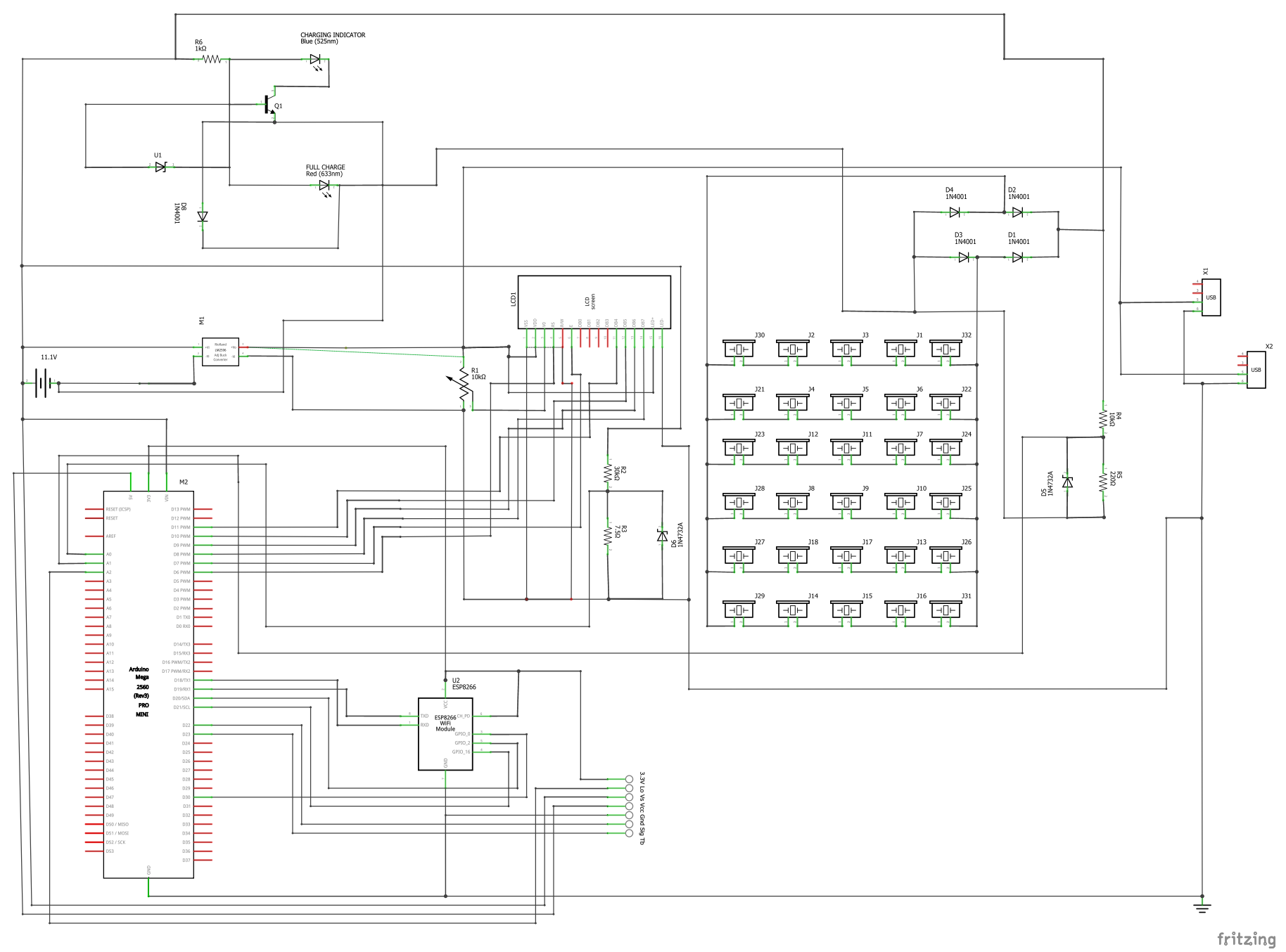
- Connect the PIR motion sensor to the Arduino. The sensor’s output pin goes to one of the Arduino’s digital input pins, D9.
- Connect the LDR to an analog input pin using a voltage divider circuit.
- Attach the LED light module to a digital output pin, using a transistor if needed for higher current loads.
- Integrate the ESP-01 module with the Arduino through UART communication (TX and RX pins).
Step 3: Programming the Arduino
Here is the Arduino code
// include the library code:
#include <LiquidCrystal.h>
#include <EEPROM.h>
#include <BigCrystal.h>
#include <BigFont.h>
#include <SoftwareSerial.h>

// initialize the library with the numbers of the interface pins
LiquidCrystal lcd(9, 13, 22, 25, 27, 29);
BigCrystal bigCrystal(&lcd);

int volt;
float voltage1;

float low = 3.2;
float full = 10.0;
//for the ESP-01
#define gpio0 18  //used for software serial
#define gpio1 28
#define gpio2 20  //used for software serial
#define gpio3 30
//the serial comm.
SoftwareSerial arduino(gpio2, gpio0);
//for LDR
#define ldrPin A2
//for pirSensor
#define pirSensorPin 7
//for the transistor
#define transistorBase 11

// Define analog input for battery
#define ANALOG_IN_PIN A1
// Floats for ADC voltage & Input voltage
float adc_voltage = 0.0;
float in_voltage = 0.0;
// Floats for resistor values in divider (in ohms)
float R1 = 32380.0;
float R2 = 11760.0;
// Float for Reference Voltage
float ref_voltage = 5.0;
// Integer for ADC value
int adc_value = 0;

//define parameters for piezo generator
float R3 = 30000.0;
float R4 = 7500.0;
#define ANALOG_IN_PIN1 A0
// Floats for ADC voltage & Input voltage
float adc_voltage1 = 0.0;
float in_voltage1 = 0.0;
// Float for Reference Voltage
float ref_voltage1 = 5.0;
// Integer for ADC value
int adc_value1 = 0;
int readButton;


void setup() {
  // set up the LCD's number of columns and rows:
  lcd.begin(20, 4);
  Serial.begin(9600);
  arduino.begin(115200);
  //declare the inputs and outputs
  pinMode(transistorBase, OUTPUT);
  pinMode(pirSensorPin, INPUT);
  pinMode(ldrPin, INPUT);
  pinMode(gpio1, INPUT);
  pinMode(gpio3, INPUT);
  //write a welcome msg on lcd
  lcd.setCursor(2, 0);
  lcd.print("...WELCOME...");
  lcd.setCursor(3, 1);
  lcd.print("MR. BUKOLA ");
  delay(3000);
  lcd.clear();
  lcd.setCursor(4, 0);
  lcd.print("FOOT-STEP");
  lcd.setCursor(2, 1);
  lcd.print("PIEZOELECTRIC");
  lcd.setCursor(3, 2);
  lcd.print(" GENERATOR");
  lcd.setCursor(3, 30);
  lcd.print("  PROJECT");
  delay(3000);
  lcd.clear();
  for (int x = 0; x < 16; x++) {
    lcd.setCursor(0, 0);
    lcd.print("Checking Battery  ");
    lcd.setCursor(x, 1);
    lcd.print("*");
    delay(200);
  }
  lcd.clear();
}

float readBatteryVoltage() {
  // Read the Analog Input
  adc_value = analogRead(ANALOG_IN_PIN);

  // Determine voltage at ADC input
  adc_voltage = (adc_value * ref_voltage) / 1024.0;

  // Calculate voltage at divider input
  in_voltage = adc_voltage * (R1 + R2) / R2;

  // Print results to Serial Monitor to 2 decimal places
  // Serial.print("Input Voltage = ");
  // Serial.println(in_voltage, 2);
  return in_voltage;
}

float readPiezoGenVoltage() {
  // Read the Analog Input
  adc_value1 = analogRead(ANALOG_IN_PIN1);

  // Determine voltage at ADC input
  adc_voltage1 = (adc_value1 * ref_voltage1) / 1024.0;

  // Calculate voltage at divider input
  in_voltage1 = adc_voltage1 * (R3 + R4) / R4;

  // Print results to Serial Monitor to 2 decimal places
  // Serial.print("Input Voltage = ");
  // Serial.println(in_voltage1, 2);
  return in_voltage1;
}

int readOnlineStreetlightButton() {
  readButton = digitalRead(gpio1);
  Serial.print("Online Control Button: ");
  Serial.println(readButton);
  return readButton;
}

int checkNightTime() {
  readOnlineStreetlightButton();
  int checkLDR = analogRead(ldrPin);
  int checkPir = digitalRead(pirSensorPin);
  if (readButton == 1) {
    if (checkLDR < 200) {
      analogWrite(transistorBase, 25);
      if (checkPir == 1) {
        analogWrite(transistorBase, 255);
      }
    } else {
      digitalWrite(transistorBase, LOW);
    }
  }

  else {
  Serial.println("remote control disabled");
  }

  Serial.print("LDR reading: ");
  Serial.print(checkLDR);
  Serial.print(" PIR reading: ");
  Serial.println(checkPir);
}

void displayBattVoltage() {
  readBatteryVoltage();
  float batPercent = map(in_voltage, 0.11, 4.2, 0.0, 100.0);
  // Serial.print(batPercent);
  // Serial.println();
  batPercent = constrain(batPercent, 0, 99);
  // buffer to hold the converted variable having a length that is +1 of the variable lentgh
  char buffer[5];
  itoa(batPercent, buffer, 10);
  //dtostrf (floatVar, minStringWidthIncDecimalPoint, numVarsAfterDecimal, charBuf)
  // char buffer[5];
  //  dtostrf (batPercent, 0, 1, buffer);
  bigCrystal.printBig(buffer, 0, 0);
  bigCrystal.print("%");
  int number_count = 1;
  int number_temp = int(batPercent);
  while (number_temp != 0) {
    number_count++;
    number_temp /= 10;
  }
  number_count -= 1;
  if (batPercent < 1) { number_count = 1; }
  lcd.setCursor(0 + (number_count * 4), 0);
  bigCrystal.print(in_voltage);
  bigCrystal.print("V  ");
  lcd.setCursor(1 + (number_count * 4), 1);
  lcd.print(" BAT   ");


  Serial.print("Bat3 Percent:  ");
  Serial.print(batPercent);
  Serial.print("%");

  Serial.print(" Batt Voltage: ");
  Serial.print(in_voltage);  //print the voltge
  Serial.print("V");

  Serial.print(" Batt analogRead: ");
  Serial.println(adc_value);
}


void displayPiezoGen() {
  readPiezoGenVoltage();
  int readPiezoPin = analogRead(A0);
  // buffer to hold the converted variable having a length that is +1 of the variable lentgh
  char buffer[5];
  itoa(in_voltage1, buffer, 10);
  bigCrystal.printBig(buffer, 0, 2);
  bigCrystal.print("V");
  int number_count = 1;
  int number_temp = int(in_voltage1);
  while (number_temp != 0) {
    number_count++;
    number_temp /= 10;
  }
  number_count -= 1;
  if (in_voltage1 < 1) { number_count = 1; }
  lcd.setCursor(0 + (number_count * 4), 2);
  bigCrystal.print("  Piezo    ");
  lcd.setCursor(1 + (number_count * 4), 3);
  lcd.print(" Gen     ");
  Serial.print("Piezo Pin: ");
  Serial.print(readPiezoPin);
  Serial.print(" Piezo Voltage: ");
  Serial.print(in_voltage1);  //print the voltge
  Serial.println("V");
}


void loop() {
  checkNightTime();
  displayBattVoltage();
  displayPiezoGen();
  //send to the ESP01 dev board via serial comm.
  arduino.print(in_voltage);
  arduino.print("A");
  arduino.print(in_voltage1);
  arduino.print("B");
  arduino.print("\n");

  delay(1000);
  Serial.println("\n");
}
Explanation of Arduino Code
- The Arduino code reads motion data from the PIR sensor.
- Checks ambient light levels using the LDR.
- Activates the LED when motion is detected and it’s dark.
- Sends battery voltage and charging status data to the ESP-01 module.
Step 4: Configuring the ESP-01 Module
- Flash the ESP-01 with firmware compatible with your IoT platform (e.g., Blynk or ThingSpeak).
- Use AT commands to connect the module to your Wi-Fi network.
- Configure the ESP-01 to upload battery data and charging voltage to your chosen IoT platform.
Step 5: Testing and Troubleshooting
- Walk over the footstep generator to charge the battery.
- Ensure the streetlight turns on only when motion is detected and it’s dark.
- Check if the ESP-01 uploads real-time data accurately.
Applications of the Smart Streetlight
- Public Pathways: Illuminate walkways using human energy.
- Campus Lighting: Use the system in schools and universities to promote sustainability.
- Remote Areas: Implement in areas without access to the power grid.
- Sports Arenas: Install in stadiums to harness the energy of large crowds.
Benefits of the Project
- Cost Efficiency: Reduces electricity bills.
- Environmentally Friendly: Promotes renewable energy.
- IoT Integration: Provides data for monitoring and optimization.
- Scalability: Can be adapted for larger systems.
Potential Improvements
- Enhanced Energy Storage: Use higher-capacity batteries.
- Advanced Sensors: Integrate ultrasonic sensors for better motion detection.
- Solar Backup: Combine footstep energy with solar panels for continuous power.
- Advanced Analytics: Use AI to analyze energy usage and optimize performance.
Conclusion
Building a DIY smart streetlight powered by footstep energy is not only a fun and educational project but also a meaningful step toward sustainability. With its combination of renewable energy, smart technology, and IoT integration, this project has the potential to revolutionize how we think about public lighting.
So why wait? Gather your components, follow the steps, and start building your own smart streetlight today!
FAQs
1. Can I use a different microcontroller instead of Arduino?
Yes, you can use other microcontrollers like ESP32 or Raspberry Pi, but you’ll need to adapt the code and connections accordingly.
2. How much energy can the footstep generator produce?
The energy output depends on the number and type of piezoelectric discs used. Typically, it’s enough to charge small batteries for low-power devices.
3. What IoT platforms can I use for this project?
Popular options include Blynk, ThingSpeak, and Adafruit IO.
4. Is the system weatherproof?
You’ll need to encase the components in waterproof housing for outdoor use.
5. Can I add more sensors to the system?
Absolutely! You can add temperature, humidity, or air quality sensors for additional functionality.

