If you’ve ever experienced the frustration of power interruptions, you know how essential it is to have a reliable backup power system. This project, the IoT-Based Automatic Changeover with Auto Generator Start/Stop, is a game-changer. It ensures seamless power transfer between a public utility grid and a generator, all while keeping you informed and in control via IoT. Sounds cool, right? Let’s dive into how this project was built but first, a brief summary…
Summary of IoT Based Automatic Changeover With Auto Gen Start/Stop Project Design

This project focuses on an IoT-based automatic changeover system that seamlessly transitions power supply between the public utility grid and a generator. The system utilizes a smart sensor (PZEM module) to monitor grid parameters (voltage, current, power factor, etc.). When grid conditions are safe, it switches to grid power and turns off the generator. Upon grid interruption, the system attempts to start the generator four times. If unsuccessful, it notifies the owner via SMS and displays an error on an LCD. Successful generator starts and grid restoration are also communicated to the owner via SMS. The IoT component, implemented with Blynk, allows for remote control of the generator and real-time monitoring of grid and generator parameters, enabling manual switching even during unsafe grid conditions at owner’s will.
Read Also: Arduino Magnetic Field Detector With Magnetic Sensor
What Is an IoT-Based Automatic Changeover System?

An IoT-based automatic changeover system automates the process of switching power sources. It transitions from grid power to a generator (and vice versa) without manual intervention. Add the IoT magic, and you get real-time monitoring, notifications, and remote control at your fingertips.
Why Build an Automatic Changeover System?
Think about it: no more rushing to start your generator during a blackout or fretting over whether the grid supply is back. This system handles it all—it even alerts you if something goes wrong. Plus, it’s perfect for homes, small businesses, and remote setups where consistent power is a must.
Key Features of the Design

- Automatic Switching: Seamless transition between grid and generator power.
- Smart Sensors: Voltage, current, power factor, and energy monitoring via the PZEM module.
- Fault Detection: Displays and notifies you if the generator fails to start.
- IoT Integration: Remote control and monitoring through the Blynk app.
- SMS Notifications: Alerts for power changes and faults.
- Backup Power: A 12V rechargeable battery keeps the system alive during blackouts.
Components Used in the Project

Here’s a breakdown of the components you’ll need:
Hardware
- Microcontroller: Smartech project board, you can order one here.
- PZEM Module: For monitoring voltage, current, power, and energy.
- Relay Module: A 2-channel relay module for switching between grid and generator.
- 12V Battery: A lead-acid rechargeable battery for backup.
- LCD Display: To show system status and parameters.
- Ignition Circuit: For starting the generator.
- LED Indicators: To display the current power source.
- Miscellaneous: Jumper wires, resistors, and a casing for safety.

The PZEM module was used to measure the voltage, current, power factor, power and energy of both the utility supply (grid) and the generator source before actually switching to that source. It also makes these measured parameters available to be displayed on the LCD screen and the IoT dashboard

This is a 30A 2-channel relay module for switching between grid and generator.
Software
- Arduino IDE: For programming the microcontroller.
- Blynk App: For IoT monitoring and control.
- SMS API: For sending alerts to the user.
How Does It Work?
This system operates in a loop, constantly monitoring the grid’s status. Here’s a step-by-step breakdown:
1. Grid Monitoring

The PZEM module keeps an eye on voltage, current, and power factor. If the grid supply is stable and within safe limits, the system switches to grid power.
2. Generator Activation
When the grid fails, the system tries to start the generator. It makes up to four attempts. If the generator starts, the system switches to generator power and notifies the user.
3. Fault Handling
If the generator fails after four attempts, the system displays a fault message on the LCD and sends an SMS to the user.
4. Switch Back to Grid
When the grid is restored and stable, the system switches back to grid power and turns off the generator. An SMS notification confirms the transition.
5. IoT Monitoring and Control

Through the Blynk app, you can:
- Monitor grid and generator parameters.
- Manually switch power sources.
- Receive notifications for transitions and faults.
Advantages of IoT Integration
Why add IoT to an automatic changeover system? Here’s why:
- Real-Time Alerts: Get instant updates on power source changes or generator faults.
- Remote Control: Switch the generator on/off from anywhere.
- Enhanced Monitoring: Keep tabs on voltage, current, and energy consumption.
- User-Friendly Dashboard: View all data in an organized format on your smartphone.
The Schematic Diagram
The schematic diagram of this project design is proprietary but I will release some part of it that, if you need it. You can contact us here on WhatsApp or Telegram to get a copy of it. Or you can simply shoot us an email here.

Explanation of The schematic diagram
The PCB board was designed around the ATmega328P. This is the brain that controls the whole circuitry. If you know how to build an Arduino Standalone board you can pass on getting this Smartech PCB because a bigger portion of it is built off the Arduino Standalone board.
There are two 30A relays that are controlled by an octo-coupler. The 2 indicator are wired in such a way that the Red LED would signify power where the blue (or green) LED would show that the system design is running.
We can program this board using the FTDI programmer USB cable. This has 6 pinouts that is connected as shown in the circuit diagram above. The Smartech PCB board has an option for extra 3 5V-relays and we used 2 of these to control the turning on and turn off of the generator as at when needed.
Since we needed the project to be IoT based, we connected an ESP-01 module that would communicate with the Atmega328P MCU. Also we connected a SIM800L to send SMS alert to the user when some set conditions are met.
Arduino Source Code
The Arduino source code for this project is divided into two part namely: The Arduino code that runs on the Atmel chip and the Arduino code that runs on the ESP-01 module. Below is the code that run on the Atmel chip
//include the libraries used for the program
#include <PZEM004Tv30.h>        //include the PZEM lib
#include <Wire.h>               //include the I2C lib
#include <LiquidCrystal_I2C.h>  //include the I2C LCD lib
#include <SoftwareSerial.h>
#include "RTClib.h"

//define the pins that control the live and neutral lines
#define houseLiveWire 11
#define houseNeutralWire 12
#define kickStartRelay 8
#define GenStateRelay 7
#define GenSupplyPin A2
#define onlineGenButton A1
const int lampPin1 = A3  ;

int ledPin = 13; // Pin connected to the LED
int blinkCount = 0; // Variable to track the number of blinks
String nullMessage = "is UNSUCCESSFUL";

bool GenMode, NepaMode, onUtility, onGen;
// Variables will change:
int ledState = LOW;
unsigned long previousMillis = 0;  // will store last time LED was updated

// constants won't change:
const long interval = 1000;

char checkStatus;
String number = "+2348103131467";  //-> change with your number
String textMessage, showMessage;
char mode = 'r';

String message1 = "Generator turned on";
String message2 = "Generator turned off";
String message3 = "Utility power restored, Generator turned off";
String message4 = "Utility power interrupted, Generator started";
String message5 = "Utility power too low, Generator turned on";

//define the serial comm. pins for the PZEM and MCU
PZEM004Tv30 pzem(4, 5);  // Software Serial pin 4 (RX) & 5 (TX)
SoftwareSerial arduino(2, 3);

// set the LCD address to 0x3F for a 16 chars and 2 line display
LiquidCrystal_I2C lcd(0x27, 16, 4);
//define variables
float currentRead, voltageRead, pfRead,frequencyRead, powerRead, energyRead;
// Floats for resistor values in divider (in ohms)
float R3 = 10000.0;
float R4 = 15000.0;
float adc_Genvoltage = 0.0;
float in_Genvoltage, in_GenCurrent, in_GenFrequency, in_GenPower, in_GenEnergy, in_GenPf;
// Float for Reference Voltage
float ref_voltage = 5.0;
int adc_Genvalue = 0;
int readGenSensor;
bool sendOnce = true;
bool reset = 0;

RTC_Millis rtc;

void setup() {
  Serial.begin(115200);
  arduino.begin(115200);
  pinMode(onlineGenButton, INPUT);
  lcd.init();       //begin the I2C lcd
  lcd.clear();      //clear the LCD
  lcd.backlight();  // Make sure backlight is on
  //state the inputs and putputs
  pinMode(houseLiveWire, OUTPUT);
  pinMode(houseNeutralWire, OUTPUT);
  pinMode(kickStartRelay, OUTPUT);
  pinMode(GenStateRelay, OUTPUT);
  pinMode(GenSupplyPin, INPUT);
  pinMode(lampPin1, OUTPUT);
  // By default the LED is off
  digitalWrite(lampPin1, LOW);

  // Print a message on both lines of the LCD.
  lcd.setCursor(2, 0);  //Set cursor to character 2 on line 0
  lcd.print("Hello world!");

  lcd.setCursor(0, 1);  //Move cursor to character 2 on line 1
  lcd.print("Welcome Emmanuel");
  delay(3000);
  lcd.clear();  //clear the LCD

  #ifndef ESP8266
    while (!Serial); // wait for serial port to connect. Needed for native USB
#endif

    // following line sets the RTC to the date & time this sketch was compiled
  rtc.begin(DateTime(F(__DATE__), F(__TIME__)));
    // This line sets the RTC with an explicit date & time, for example to set
    // January 21, 2014 at 3am you would call:
    // rtc.adjust(DateTime(2014, 1, 21, 3, 0, 0));
}
////WHEN TURNING ON THE GENERATOR IGNITION, THE "ON" STATE IS WHEN  PINS 1 & 6 IS DISCONNECTED////
///PINs 2 & 5 is ALSO DISCONNECTED.////
////THE OFF STATE IS WHEN THESE ABOVE PINS ARE CONNECTED////
////HOWEVER, TO START, PINS 3 & 4 MUST BE CONNECTED WHILE THE FIRST 4 PINS ABOVE WILL DISCONNECT////
////TO TURN OFF GENERATOR, PINS 1 & 6 CONNECTED, PINS 2 & 5 CONNECTED and  PINS 3 & 4 DISCONNECTED////
void startGen(){
  // if (trialTimes == true) {
    // blinkCount = 0;
if (blinkCount < 4) { // Check if the number of blinks is less than 5
    digitalWrite(ledPin, HIGH); // Turn the LED on
    turnOnGen();
    delay(300); // Wait for 100 milliseconds
    startIgna();
    delay(3000);
    GenVoltageLevel(); //check the supply voltage of Gen
    if (in_Genvoltage >= 80.00) {
    Serial.println("Gen started successfully");
    blinkCount = 5;
    }
    digitalWrite(ledPin, LOW); // Turn the LED off
    Serial.println("Couldn't start Gen");
    delay(2000); // Wait for 2000 milliseconds
    turnOnGen();
    blinkCount++; // Increment the blink count
  }
    else {
    // If the number of blinks is 5, do nothing
    Serial.println("Max. number of trials reached");
      }
      Serial.print("Trial Times = ");
      Serial.println(blinkCount);
  }


void startIgna() {
  digitalWrite(kickStartRelay, HIGH);
  digitalWrite(GenStateRelay, LOW);
}
void turnOnGen() {
  digitalWrite(kickStartRelay, LOW);
  digitalWrite(GenStateRelay, LOW);
}
void turnOffGen() {
  digitalWrite(kickStartRelay, LOW);
  digitalWrite(GenStateRelay, HIGH);
}

float GenVoltageLevel(){
   readGenSensor = analogRead(GenSupplyPin);
  // Determine voltage at ADC input
   adc_Genvoltage  = (readGenSensor * ref_voltage) / 1024.0;
   // Calculate voltage at divider input
   in_Genvoltage = adc_Genvoltage / (R4/(R3+R4)) ;
   in_Genvoltage = map(in_Genvoltage, 0.01, 7.90, 12.00, 240.00);
   in_Genvoltage = constrain(in_Genvoltage, 12.00, 240.00);
   if(in_Genvoltage >= 70){
      in_GenCurrent = 0.429;
      in_GenFrequency = 46.0;
      in_GenPf = 1.3;
      in_GenPower = in_GenCurrent * in_Genvoltage;
      in_GenEnergy = in_GenPower * 0.1;
   }
   if(in_Genvoltage <= 30){
      in_GenCurrent = 0.0;
      in_GenFrequency= 0.0;
      in_GenPf = 0.0;
      in_GenPower = in_GenCurrent * in_Genvoltage;
      in_GenEnergy = in_GenPower * 0.1;
   }
  // Serial.print("Gen Voltage Level: ");
  // Serial.println(in_Genvoltage);
  return in_Genvoltage, in_GenCurrent, in_GenEnergy, in_GenFrequency, in_GenPf, in_GenPower;
}

float pzemEnergyReadings() {
  float voltage = pzem.voltage();
  if (voltage != NAN) {
    // Serial.print("Voltage: ");
    // Serial.print(voltage);
    // Serial.println("V");
  } else {
    Serial.println("Error reading voltage");
  }

  float current = pzem.current();
  if (current != NAN) {
    // Serial.print("Current: ");
    // Serial.print(current, 2);
    // Serial.println("A");
  } else {
    Serial.println("Error reading current");
  }

  float power = pzem.power();
  if (current != NAN) {
    // Serial.print("Power: ");
    // Serial.print(power);
    // Serial.println("W");
  } else {
    Serial.println("Error reading power");
  }

  float energy = pzem.energy();
  if (current != NAN) {
    // Serial.print("Energy: ");
    // Serial.print(energy, 2);
    // Serial.println("kWh");

  } else {
    Serial.println("Error reading energy");
  }

  float frequency = pzem.frequency();
  if (current != NAN) {
    // Serial.print("Frequency: ");
    // Serial.print(frequency, 0);
    // Serial.println("Hz");
  } else {
    Serial.println("Error reading frequency");
  }

  float pf = pzem.pf();
  if (current != NAN) {
    // Serial.print("PF: ");
    // Serial.println(pf);
  } else {
    Serial.println("Error reading power factor");
  }
  voltageRead = voltage;
  currentRead = current;
  powerRead = power;
  energyRead = energy;
  frequencyRead = frequency;
  pfRead = pf;
  return currentRead, voltageRead, powerRead, energyRead, frequencyRead, pfRead;
}


bool checkGenParameters(){
  GenVoltageLevel();
  if(in_Genvoltage <= 50){
    GenMode = false;
  }
   if(in_Genvoltage >= 60){
    GenMode = true;
  }
  return GenMode;
}

bool checkNepaParameters(){
pzemEnergyReadings();
//check if there Utility voltage and if it is within safe range and turn on to switch to NEPA
  if ((voltageRead >= 160) && (voltageRead <= 241)) {
    digitalWrite(houseLiveWire, HIGH);
    digitalWrite(houseNeutralWire, HIGH);
    Serial.println("NEPA TURNED ON");
    turnOffGen();
    checkGenParameters();
    if (GenMode == false) {
    checkStatus = 'y';
    if (sendOnce == true) {
    SendMessage();
    }
    sendOnce = false;
    }
    NepaMode = true;
  }
  //if however it is low voltage or high voltage turn off utility
  if (((voltageRead >= 30) && (voltageRead <= 89)) || (voltageRead >= 281)) {
    digitalWrite(houseLiveWire, LOW);
    digitalWrite(houseNeutralWire, LOW);
    //Serial.println("NEPA TURNED OFF");
    NepaMode = false;
    startGen();
    checkGenParameters();
    if (GenMode == true) {
    checkStatus = 'x';
    if (sendOnce == true) {
    SendMessage();
    }
    sendOnce = false;
    }
    //Serial.println("GEN TURNED ON DUE TO LOW OR HIGH VOLTAGE");
  }
  //if there is no utility voltage, switch back to Generator
  if ((isnan(voltageRead)) || ((voltageRead >= 1) && (voltageRead <= 29))) {
    lcd.clear();
    digitalWrite(houseLiveWire, LOW);
    digitalWrite(houseNeutralWire, LOW);
    //Serial.println("NEPA TURNED OFF");
    NepaMode = false;
    startGen();
    checkGenParameters();
    if (GenMode == true) {
    checkStatus = 'k';
    if (reset == 0) {
    SendMessage();
    }
     reset = 1;
   }
    //Serial.println("GEN TURNED ON DUE TO NO UTILITY SUPPLY");
  }
  return NepaMode;
}

void lcdDisplayGenValues(){
  GenVoltageLevel();
    //send to the ESP01 dev board via serial comm.
  arduino.print(in_Genvoltage);     arduino.print("A");
  arduino.print(in_GenCurrent);     arduino.print("B");
  arduino.print(in_GenPower);       arduino.print("C");
  arduino.print(in_GenEnergy);      arduino.print("D");
  arduino.print(in_GenFrequency);   arduino.print("E");
  arduino.print(in_GenPf);          arduino.print("F");
  arduino.print("\n");
//print the energy parameters on the LCD
  lcd.setCursor(1, 0);  //print current
  lcd.print("Cur ");
  lcd.setCursor(0, 1);
  lcd.print(in_GenCurrent);
  lcd.print("A");
  //print voltage
  lcd.setCursor(6, 0);
  lcd.print("Volt ");
  lcd.setCursor(6, 1);
  lcd.print(in_Genvoltage, 0);
  lcd.print("V");
  //print the frequency
  lcd.setCursor(12, 0);
  lcd.print("FRQ ");
  lcd.setCursor(12, 1);
  lcd.print(in_GenFrequency, 0);
  lcd.print("Hz");
  //print the power
  lcd.setCursor(-3, 2);  //Move cursor to character 1 on line 3
  lcd.print("PWR ");
  lcd.setCursor(-4, 3);
  lcd.print(in_GenPower, 0);
  lcd.print("W");
  //print energy
  lcd.setCursor(2, 2);
  lcd.print("ENGY ");
  lcd.setCursor(1, 3);
  lcd.print(in_GenEnergy, 2);
  lcd.print("kWH");
  //print the power factor
  lcd.setCursor(9, 2);
  lcd.print("P.F ");
  lcd.setCursor(9, 3);
  lcd.print(in_GenPf, 1);
    //print out the values read on the S. monitor
  Serial.print("Voltage: ");
  Serial.print(voltageRead);
  Serial.print("V");
  Serial.print(" Current: ");
  Serial.print(currentRead, 4);
  Serial.print("A");
  Serial.print(" Power: ");
  Serial.print(powerRead);
  Serial.print("W\n");
  Serial.print(" Energy: ");
  Serial.print(energyRead, 2);
  Serial.print("kWh");
  Serial.print(" Frequency: ");
  Serial.print(frequencyRead, 0);
  Serial.print("Hz");
  Serial.print(" Power Factor: ");
  Serial.println(pfRead);
}


void lcdDisplayNepaValues() {
    //send to the ESP01 dev board via serial comm.
  arduino.print(voltageRead);     arduino.print("A");
  arduino.print(currentRead);     arduino.print("B");
  arduino.print(powerRead);       arduino.print("C");
  arduino.print(energyRead);      arduino.print("D");
  arduino.print(frequencyRead);   arduino.print("E");
  arduino.print(pfRead);          arduino.print("F");
  arduino.print("\n");
  //print the energy parameters on the LCD
  lcd.setCursor(1, 0);  //print current
  lcd.print("Cur ");
  lcd.setCursor(0, 1);
  lcd.print(currentRead);
  lcd.print("A");
  //print voltage
  lcd.setCursor(6, 0);
  lcd.print("Volt ");
  lcd.setCursor(6, 1);
  lcd.print(voltageRead, 0);
  lcd.print("V");
  //print the frequency
  lcd.setCursor(12, 0);
  lcd.print("FRQ ");
  lcd.setCursor(12, 1);
  lcd.print(frequencyRead, 0);
  lcd.print("Hz");
  //print the power
  lcd.setCursor(-3, 2);  //Move cursor to character 1 on line 3
  lcd.print("PWR ");
  lcd.setCursor(-4, 3);
  lcd.print(powerRead, 0);
  lcd.print("W");
  //print energy
  lcd.setCursor(2, 2);
  lcd.print("ENGY ");
  lcd.setCursor(1, 3);
  lcd.print(energyRead, 2);
  lcd.print("kWH");
  //print the power factor
  lcd.setCursor(9, 2);
  lcd.print("P.F ");
  lcd.setCursor(9, 3);
  lcd.print(pfRead, 1);
}

bool displayOnWhichSource(){
  checkGenParameters();
  checkNepaParameters();

  // Serial.print("Gen Parametrs is:");
  // Serial.print(checkGenParameters());
  // Serial.print(" ");
  // Serial.print("NEPA parameters is: ");
  // Serial.println(checkNepaParameters());
  if((checkGenParameters() == false)&&(checkNepaParameters() == false)){
      onUtility = false;
      onGen = true;
      lcd.clear();
      lcd.setCursor(1, 0);
      lcd.print("  DEVICE ON");
      lcd.setCursor(0, 1);
      lcd.print("GENERATOR SOURCE");
      lcd.setCursor(-3, 2);
      lcd.print("SEE VALUES IN...");
     for (int i=4; i>=1; i--) {
        lcd.setCursor(2, 3);
      lcd.print(i);
      delay(500);
      }
  }

  if((checkGenParameters() == true)&&(checkNepaParameters() == false)){
      onUtility = false;
      onGen = true;
      lcd.clear();
      lcd.setCursor(1, 0);
      lcd.print("  DEVICE ON");
      lcd.setCursor(0, 1);
      lcd.print("GENERATOR SOURCE");
      lcd.setCursor(-3, 2);
      lcd.print("SEE VALUES IN...");
      for (int i=4; i>=1; i--) {
        lcd.setCursor(2, 3);
      lcd.print(i);
      delay(500);
      }
  }

  if((checkGenParameters() == false)&&(checkNepaParameters() == true)){
      onUtility = true;
      onGen = false;
      lcd.clear();
      lcd.setCursor(1, 0);
      lcd.print("  DEVICE ON");
      lcd.setCursor(0, 1);
      lcd.print("  UTILITY GRID");
      lcd.setCursor(-3, 2);
      lcd.print("SEE VALUES IN...");
    for (int i=4; i>=1; i--) {
        lcd.setCursor(2, 3);
      lcd.print(i);
      delay(500);
      }
      }

  if((checkGenParameters() == true)&&(checkNepaParameters() == true)){
  onUtility = true;
  onGen = false;
  lcd.clear();
      lcd.setCursor(1, 0);
      lcd.print("  DEVICE ON");
      lcd.setCursor(0, 1);
      lcd.print("  UTILITY GRID");
      lcd.setCursor(-3, 2);
      lcd.print("SEE VALUES IN...");
    for (int i=4; i>=1; i--) {
        lcd.setCursor(1, 3);
      lcd.print(i);
      delay(500);
    }
  }
  return onUtility, onGen;
}

void displaySourceParameters(){
  displayOnWhichSource();
  if(onUtility){
    lcd.clear();
    lcdDisplayNepaValues();
  }
  if(onGen){
    lcdDisplayGenValues();
  }
}

int checkGenOnlineButton(){
   checkGenParameters();
  checkNepaParameters();
  int readOnlineButton = digitalRead(onlineGenButton);
  if (readOnlineButton == HIGH) {
  if ((GenMode == false) || (NepaMode == false)) {
    blinkCount = 0;
       startGen();
    if (sendOnce == true) {
    SendMessage();
    }
    sendOnce = false;
  }
  }
  else if (readOnlineButton == LOW) {
       Serial.print(" Blink Count: ");
        Serial.println(blinkCount);
        }
    Serial.print("readOnlineButton: ");
  Serial.println(readOnlineButton);
}

void loop() {
  RecieveMessage();
    checkGenOnlineButton();
  DateTime now = rtc.now();
  if(((now.second() >= 0) && (now.second() <= 3)) || ((now.second() >= 9) && (now.second() <= 11)) || ((now.second() >= 17) && (now.second() <= 19)) || ((now.second() >= 26) && (now.second() <= 28)) || ((now.second() >= 34) && (now.second() <= 36)) || ((now.second() >= 42) && (now.second() <= 44)) || ((now.second() >= 50) && (now.second() <= 52))){
       displayOnWhichSource();
      //  Serial.print("\nHello there?");
   //
  }
  if(((now.second() >= 4) && (now.second() <= 8)) || ((now.second() >= 12) && (now.second() <= 16)) || ((now.second() >= 20) && (now.second() <= 25)) || ((now.second() >= 29) && (now.second() <= 33)) || ((now.second() >= 37) && (now.second() <= 41)) || ((now.second() >= 45) && (now.second() <= 49)) || ((now.second() >= 53) && (now.second() <= 59))){
    displaySourceParameters();
    // Serial.print("\nYes, I read You, How can I help?");
  }
     delay(1000);

}

char RecieveMessage() {
  // AT command to set SIM900 to SMS mode
  Serial.println(" Now ready to receive SMS");
  Serial.print("AT+CMGF=1\r");
  delay(100);
  // Set module to send SMS data to serial out upon receipt
  Serial.print("AT+CNMI=2,2,0,0,0\r");
  delay(100);
  if (Serial.available() > 0) {
    textMessage = Serial.readString();
    Serial.print(textMessage);
    delay(10);
    //Control the LAMP 1
    if (textMessage.indexOf("Start gen") >= 0) {
      digitalWrite(lampPin1, HIGH);
      blinkCount = 0;
      startGen();
      checkGenParameters();
      if(GenMode == true){
          checkStatus = 'a';
          SendMessage();
      }
    }

    if (textMessage.indexOf("Turn gen off") >= 0) {
      digitalWrite(lampPin1, LOW);
      turnOffGen();
      checkGenParameters();
      if (GenMode == false) {
      checkStatus = 'b';
      SendMessage();
      }

    }
  }
}

void dummy() {
  Serial.println("AT+CMGF=1");  //Sets the GSM Module in Text Mode
  delay(200);
  Serial.println("AT+CMGS=\"" + number + "\"\r");  //Mobile phone number to send message
  delay(200);
}

void SendMessage() {
  Serial.println(checkStatus);
  switch (checkStatus) {
    case 'a':
      dummy();
      Serial.println("Hello," + message1);
      break;
    case 'b':
      dummy();
      Serial.println("Hello," + message2);
      break;
    case 'y':
      dummy();
      Serial.println("Hello," + message3);
      break;
    case 'x':
      dummy();
      Serial.println("Hello," + message5);
      break;
    case 'k':
      dummy();
      Serial.println("Hello," + message4);
      break;
      //      default:
      //        dummy();
      //        sim.println("Hello," + nullMessage);
  }
  updateSerial();
  delay(100);
  Serial.println((char)26);  // ASCII code of CTRL+Z
  delay(200);
  checkStatus = 'z';
}

void updateSerial() {
  delay(5);
  while (Serial.available()) {
    Serial.write(Serial.read());  //Forward what Serial received to Software Serial Port
  }
  while (Serial.available()) {
    Serial.write(Serial.read());  //Forward what Software Serial received to Serial Port
  }
}
Step-by-Step Implementation
1. Set Up the Hardware

- Connect the PZEM module to monitor the grid.
- Wire the relay module to switch between grid and generator.
- Attach the LCD for displaying status updates.
2. Program the Microcontroller

Use the Arduino IDE to write the control logic:
- Monitor grid parameters.
- Attempt generator ignition if grid fails.
- Manage relay switching.
- Communicate with the Blynk app and SMS API.
3. Integrate IoT Features

- Set up the Blynk app. Or you can use the Zafron IoT platform as shown above.
- Add widgets for monitoring and control.
- Link the microcontroller to the app via WiFi.

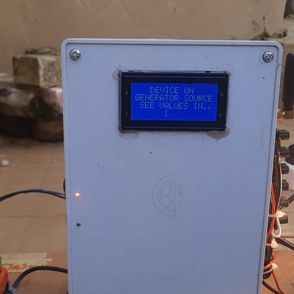
Also when it is on generator mode as shown in the image below. We can see the energy parameters displayed on both the LCD and the IoT platform on Zafron.

4. Test and Troubleshoot

- Simulate power interruptions and verify system behavior.
- Check SMS notifications and IoT dashboard updates.
- Fine-tune relay timing and ignition retries.
Practical Applications
- Homes: Reliable backup power management.
- Businesses: Maintain operations during blackouts.
- Remote Locations: Monitor and control power systems from afar.
Challenges and Solutions
- Voltage Fluctuations: The PZEM module ensures only safe grid parameters are used.
- Generator Failures: Fault notifications help users address issues promptly.
- IoT Connectivity: A strong WiFi signal is essential for seamless updates.
Future Improvements
- Battery Monitoring: Add a feature to monitor the 12V battery’s charge level.
- Advanced IoT Features: Include predictive maintenance alerts for the generator.
- Solar Integration: Allow switching to a solar power source.
Conclusion
The IoT-Based Automatic Changeover with Auto Gen Start/Stop system is a lifesaver for anyone dealing with frequent power outages. It’s smart, reliable, and easy to use. With real-time alerts, remote control, and seamless switching, you’ll never have to worry about power disruptions again. Why not give it a try and enjoy uninterrupted power?
FAQs
1. Can I use this system for three-phase power?
Yes, with additional components and modifications, you can adapt this design for three-phase systems.
2. What happens if the WiFi connection is lost?
The system continues to function locally. IoT features will resume once WiFi is restored.
3. Can I add solar power to this setup?
Absolutely! You can integrate solar panels and an inverter to create a hybrid system.
4. How do I ensure the generator starts reliably?
Regular maintenance and using a good-quality generator are key. The system will notify you if issues arise.
5. What if I want to expand the system?
You can add more sensors, relays, or IoT features as needed. The design is flexible and scalable.

