Blog

  • A robot designed after lizards that will explore Mars’ surface.

    A robot designed after lizards that will explore Mars’ surface.

    robot designed after lizards
    robot designed after lizards

    Technological developments have created fascinating opportunities for space research that may eventually yield fresh insights about the celestial objects in our galaxy. Robots have shown to be incredibly effective tools for exploring other worlds, especially Mars, a terrestrial planet in the solar system that is believed to contain some components that are comparable to those on Earth.

    It would be exciting to explore Mars and its surface in search of evidence of past or contemporary extraterrestrial life. These investigations may reveal different types of prehistoric microbial life as well as resources that are not found on Earth, opening the door for future manned expeditions to Mars.

    A new four-legged robot that was recently created by Nanjing University of Aeronautics and Astronautics in inspiration from lizards may help with surface exploration on Mars. Their robot, which was published in MDPI’s Biomimetics magazine, features a flexible body structure that can mimic the motions and mode of locomotion of a desert lizard.

    “To assist ambitious uncrewed missions to Mars, specific types of planetary rovers have been developed for performing tasks on Mars’ surface,” Guangming Chen, Long Qiao, Zhenwen Zhou, Lutz Richter and Aihong Ji wrote in their paper. “Due to the fact that the surface is composed of granular soils and rocks of various sizes, contemporary rovers can have difficulties in moving on soft soils and climbing over rocks. To overcome such difficulties, this research develops a quadruped creeping robot inspired by the locomotion characteristics of the desert lizard.”

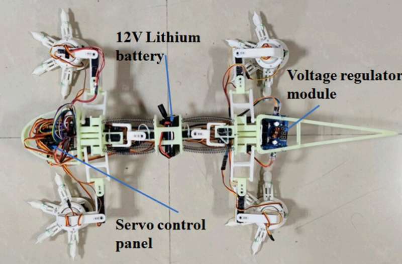
    The biomimetic robot created by Chen and his colleagues is comprised of a flexible spine-like structure and four legs. To replicate the “creeping” motion typical of lizards, every leg features two hinges and a gear that elicits a swinging movement.

    The robot can lift without losing equilibrium thanks to the four-linkage system and two servos that are used in each hip joint that connects the spinal structure to the legs. The four flexible “toes” of the robot’s “feet” are made up of two hinges and a claw.

    The researchers wrote in their study, “The leg structure incorporates a four-linkage mechanism, which assures a stable lifting motion. The foot is made up of a flexible circular pad with four toes that are good at grabbing soil and pebbles and an active ankle.

    The researchers developed a number of kinematics models for each of the parts of their robot in order to simulate lizard motions. They then planned the movements of the robot using these models and numerical calculations.

    In their research, Chen and his colleagues stated that “kinematic models relating to foot, leg, and spine are constructed” to predict robot motions. Furthermore, numerical proof is provided for the coordinated leg and trunk movements.

    To test if their robot could accurately mimic lizard movements, the researchers first put it through a series of simulations. They discovered that their robot could carry out the specified motions and walking style, which gave them highly encouraging results.

    With the use of 3D-printed resin materials, a servo control panel, a lithium battery, and other electronic components, Chen and his colleagues have already built a prototype of their robot. The movements of their prototype robot were then assessed using a testbed simulation of rocky terrain similar to those seen on Mars.

    Scientists discovered that the robot could maneuver well in difficult terrain, indicating its potential for future expeditions to Mars. The researchers will need to work on it more before it can be used and tested outside of the lab, such as by adding a sealing mechanism to keep out dirt or airborne dust and strengthening the body with more durable materials.

    Working on machine learning models will enable Chen and his team’s robot to adjust its motions to various terrains. They also intend to implement a mechanism that will supply the robot with constant electricity.

    Read More

  • Researchers have created a smart eco mode in a car driving system that can “see into the future.”

    Researchers have created a smart eco mode in a car driving system that can “see into the future.”

    driving system
    driving system

    Driving system Eco-friendly driving can help you save money and the environment by consuming less fuel. In reality, though, it frequently aggravates drivers to the point where they swiftly turn off the feature. The mode stops motorists from accelerating when they actually need to, such when turning onto a highway. Based on future forecasts, Delft robot engineers created the Proactive Eco Mode, a novel mechanism that helps drivers attain the required speed more quickly. The system has been successfully tested on French roadways.

    Aggressive eco mode

    Instead of using complicated models while creating the Proactive Eco Mode, researchers Timo Melman and Niek Beckers first concentrated on the driver and data collecting. They gathered information on a driver’s driving habits during a test at the Renault Technocentre in France. The Proactive Eco Mode was able to successfully anticipate outcomes using a straightforward algorithm after just one round of testing. When it became necessary, the driver could easily and quickly accelerate with the aid of this device while also driving more efficiently. In response, Groupe Renault responded warmly and expressed interest in using the patented technology in next automobiles.

    driving system

    Timo Melman, a researcher at the TU Delft’s Human-Robot Interaction, stated: “Our technology enables your automobile to glance ahead while you are driving. We can forecast when a driver will need a lot of power and when they won’t, and we can adjust the engine settings of the automobile accordingly. Simple algorithms are all that are needed to do this; all we have to do is gather information on the driver’s and other drivers’ driving habits. The car “knows” when you desire to accelerate as a result of this information. Staying in eco mode is now considerably more enjoyable for the driver while maintaining energy efficiency. As far as we are concerned, a win-win circumstance.”

    Partnership

    The Proactive Eco Mode was created by researchers Niek Beckers and Timo Melman in collaboration with Groupe Renault’s Xavier Mouton and professor of human-robot interaction David Abbink. The partnership between Renault and TU Delft is overseen by Professor David Abbink, who says, “This is a good illustration of how our group’s foundational research into human-robot interaction develops real-world applications.”

    These experiments relate to both AiTech, whose scientific director is Abbink, and the research field of “Meaningful human control of autonomous intelligent systems.” The mission of this institute is to create intelligent systems that are human-transparent and comprehensible.

    Read More

  • The Easiest Way For Humans to get used to Robot.

    The Easiest Way For Humans to get used to Robot.

    get use to Robot
    get use to Robot

    Researchers that study human-robot interaction frequently concentrate on comprehending human goals from the viewpoint of the robot so that the robot can learn to work with people more successfully. The human must also learn how the robot behaves since human-robot contact is a two-way street.

    Thanks to decades of cognitive science and educational psychology research, scientists have a pretty good handle on how humans learn new concepts. So, researchers at MIT and Harvard University collaborated to apply well-established theories of human concept learning to challenges in human-robot interaction.

    They examined past studies that focused on humans trying to teach robots new behaviors. The researchers identified opportunities where these studies could have incorporated elements from two complementary cognitive science theories into their methodologies. They used examples from these works to show how the theories can help humans form conceptual models of robots more quickly, accurately, and flexibly, which could improve their understanding of a robot’s behavior.

    According to Serena Booth, a graduate student in the Interactive Robotics Group of the Computer Science and Artificial Intelligence Laboratory (CSAIL) and the paper’s lead author, humans who create more accurate mental models of a robot are frequently better collaborators. This is crucial when humans and robots collaborate in high-stakes settings like manufacturing and healthcare.

    “Whether or not we make an effort to assist people in creating conceptual models of robots, they will do it nonetheless. Also, those conceptual models can be inaccurate. People may be seriously endangered as a result. We must do everything in our power to provide that person with the most accurate mental model possible “asserts Booth.

    Booth and her advisor, Julie Shah, an MIT professor of aeronautics and astronautics and the director of the Interactive Robotics Group, co-authored this paper in collaboration with researchers from Harvard. Elena Glassman ’08, MNG ’11, Ph.D. ’16, an assistant professor of computer science at Harvard’s John A. Paulson School of Engineering and Applied Sciences, with expertise in theories of learning and human-computer interaction, was the primary advisor on the project. Harvard co-authors also include graduate student Sanjana Sharma and research assistant Sarah Chung. The research will be presented at the IEEE Conference on Human-Robot Interaction.

    a theoretical strategy
    Using two major hypotheses, the researchers examined 35 studies on human-robot teaching. According to the “analogical transfer theory,” people learn by making analogies. Humans implicitly search for anything familiar they can use to grasp a new topic or notion when they deal with it.

    According to the “variation theory of learning,” deliberate variation can make concepts clear that might otherwise be challenging to understand. It contends that while dealing with a novel idea, people go through four stages: repetition, contrast, generalization, and variety.

    Although many research publications only included a portion of one theory, this was most likely accidental, according to Booth. The experiments might have been more potent if the researchers had consulted these hypotheses at the commencement of their study.

    For instance, researchers frequently show individuals numerous examples of the robot performing the same action while instructing humans to engage with a robot. But, according to variation theory, in order for people to construct an accurate mental model of that robot, they must be exposed to a variety of examples of the robot executing the task in various settings, as well as examples of the robot making mistakes.

    According to Booth, “It is exceedingly uncommon in the literature on human-robot interaction since it defies logic, but people also need to see depressing examples to realize what the robot is not.”

    The development of physical robots might benefit from these cognitive science theories. People will find it difficult to create accurate mental models of a robotic arm if it looks like a human arm but moves differently from how humans move, according to Booth. According to the analogical transfer theory, because people compare the robotic arm to the human arm they are used with, it can be confusing for them and make it harder for them to learn how to engage with the robot.

    improving the explanations

    Booth and her collaborators also studied how theories of human-concept learning could improve the explanations that seek to help people build trust in unfamiliar, new robots.

    “In explainability, we have a really big problem of confirmation bias. There are not usually standards around what an explanation is and how a person should use it. As researchers, we often design an explanation method, it looks good to us, and we ship it,” she says.

    Instead, they suggest that researchers use theories from human concept learning to think about how people will use explanations, which are often generated by robots to clearly communicate the policies they use to make decisions. By providing a curriculum that helps the user understand what an explanation method means and when to use it, but also where it does not apply, they will develop a stronger understanding of a robot’s behavior, Booth says.

    They offer some suggestions for how research on human-robot teaching can be improved in light of their results. They recommend, among other things, that researchers take into account analogical transfer theory by assisting individuals in drawing relevant similarities when they are learning to work with a new robot. According to Booth, providing direction can ensure that humans draw the appropriate comparisons so they are not taken aback or perplexed by the robot’s activities.

    Additionally, they contend that exposing users to both good and bad examples of robot behavior as well as how strategically altering a robot’s “policy” settings affects the behavior of the robot over time and in a variety of strategically advantageous environments might aid human learning. The mathematical function that makes up the robot’s policy gives probabilities to each possible course of action.

    “While we have been conducting user studies for years, we have always relied on our own instincts to determine what would or would not be beneficial to demonstrate to a human. The next step would be to be more strict about establishing the theoretical underpinnings of this work in human cognition, “says Glassman.

    Booth wants to investigate if the ideas genuinely help people learn by re-creating some of the studies she researched after she has finished her initial examination of the literature using cognitive science theories.

    Read More

  • This is a Robotic Hand With an Adjustable Grip With The Feature.

    This is a Robotic Hand With an Adjustable Grip With The Feature.

    This is a Robotic Hand With an Adjustable Grip With The Feature
    Robotic Hand

    We frequently move objects around when picking them up in an effort to achieve the best grip. A robotic hand that performs a similar function has now been created by a research team, a development that could improve the development of assistive robots.

    The group developed a robotic hand that can fully rotate a variety of objects in the lab of Aaron Dollar, professor of mechanical engineering, materials science, and computer science. This is true even when the grippers of the robotic hand occasionally lose touch with the object. In the most current issue of IEEE Robotics and Automation Letters, the findings were published.

    Lead author of the study and Ph.D. student in Dollar’s lab Andrew Morgan explained that the goal of the project was to develop a tool “where the fingers are always expanding and shutting, altering their placement on the actual object.”

    A previous Ph.D. student, Raymond Ma, developed the original concept for the hand. For the newer version, Morgan modified the design to enable more advanced in-hand capabilities. These includes new fingertip designs and an adaptation of the internal wrist rotation.

    One potential application, he said, is for assembly purposes. For instance, the device could pick up an object and reorient it so that it can insert it into a slot or place it down in a certain way.

    The researchers set out to make the hand relatively simple, with as little sensor technology as possible. The point is to make a practical device that’s not too expensive or requires too much maintenance. “It required us to make a more robust system than what has traditionally been required,” Morgan said.

    o make the gripper move, the team uses a tendon-driven, underactuated transmission, which Morgan said is “more forgiving” due to its inherent passive adaptive nature. That is, there are fewer motors than there are joints in the hand, which makes the hand move in such a way that it better “wraps” to its environment.”We don’t need to know as much about the environment as you normally would,” he said.

    One notable advance in the design is that the device also has a camera that tracks in real time the position of the object that it’s manipulating.

    “By coupling the adaptive nature of the hand and this external feedback, we were able to control the hand purely from vision, and without touch sensors,” Morgan said. “We use the feedback from this camera, so that it’s always saying ‘Hey you just took an action—how good was that action, and how can we make sure that the next action will be better?’”

    The tool was effective at manipulating variously shaped items, such as a sphere, a toy automobile, a plastic rabbit, and a plastic duck.

    In-hand manipulation tasks that have historically been very challenging for a robot to realize were “completed” by the team, according to Morgan.

    Expanding on the experiment, Morgan stated that they would like to use a wider range of things to test the device’s capabilities.

    Testing in-home chores would be interesting and important since, in the end, we’re attempting to produce more capable service robots, he said. He said that this might entail picking up plates or handling and putting a brush in a holder.

    Read More

  • Creating a robotic wheelchairs that is user-friendly for crowds

    Creating a robotic wheelchairs that is user-friendly for crowds

    robotic wheelchair
    robotic wheelchair

    In the near future, crowds may be easily and safely navigated by robotic wheelchairs. Researchers from EPFL are investigating the technical, ethical, and safety challenges associated with this type of technology as part of CrowdBot, an EU-funded project. The project’s ultimate goal is to make it easier for people with disabilities to move around.

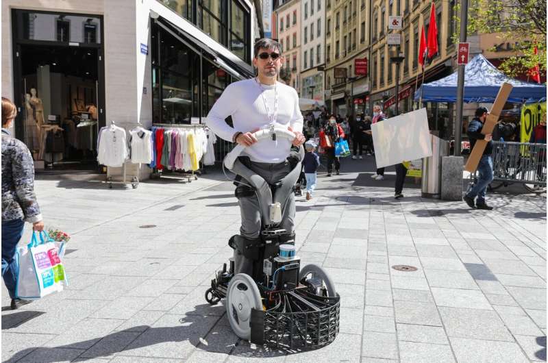
    Shoppers at Lausanne’s weekly outdoor market may have come across one of EPFL’s inventions in the past few weeks—a newfangled device that’s part wheelchair, part robot. It’s being used by researchers at EPFL’s Learning Algorithms and Systems Laboratory (LASA) to test technology they’re developing under CrowdBot, a project led by INRIA and involving a consortium of seven research organizations, including EPFL.

    The project has received funding from the EU’s Horizon 2020 program in the Information and Communication Technology (ICT) section. CrowdBot aims to test the technical and ethical feasibility of having robots move through crowded areas. These robots could be humanoids, service robots or assistive robots. “You hear a lot about self-driving cars, but not about robots that could be moving around among pedestrians,” says Aude Billard, the head of LASA. “However, robotics technology is clearly going in that direction, so we have to start thinking now about all that will imply.”

    Many potential outcomes

    The safety of robot users and those around them is the most evident issue among the many being researched. The lack of legislation that addresses this was discovered by LASA researchers, who then started to examine all the potential risks, including the possibility of colliding with a person.

    For their risk analysis, the researchers used a robot they named Qolo, which stands for Quality of Life with Locomotion. Qolo is a standing wheelchair for individuals with disabilities that was first created at the University of Tsukuba in Japan. The wearer can effortlessly transition from a seated to a standing posture thanks to the device’s two powered wheels and passive exoskeleton.

    In Bern, the LASA team tested the Qolo’s crashworthiness. Diego Paez, a postdoc at LASA, explains that “we conducted the tests with two types of dummies, as the effect of a collision can differ depending on how tall the person is.” For instance, the head is most vulnerable in youngsters, but the belly is most sensitive in pregnant women. The researchers found that even at low robot speeds, like < 6 km/h, collisions can result in severe injuries. Hence, avoiding these collisions is even more crucial.

    The use of active navigation

    Modifying Qolo to enable environment analysis and response was the first stage. The robot was outfitted by the scientists with a variety of sensors, including front-facing cameras and a Lidar system with lasers. “The robot must be able to see everything around it in 360 degrees in order to avoid obstructions in front of and behind it. Also, it needs to be aware of what is behind it in case it wants to fast reverse to avoid a collision “Paez says. “The cameras tell the robot whether the obstructions are pedestrians, and the Lidar system detects all kinds of impediments.”

    Also, the team added bumpers on Qolo’s front. According to Paez, the bumpers alert the robot when it makes touch with something and quantify the force at which it makes contact, allowing the maximum force to be kept to a minimum while the robot is still in motion. In other words, Qolo is designed to avoid obstacles rather than stopping if it encounters one. For humans nearby the robot, a sudden stop in the middle of a crowd “may be even more deadly,” the expert warns.

    To determine how many people are nearby and what directions they are travelling in, Qolo’s sensors data is merged with people detection and tracking algorithms. In order for Qolo to react fast in crowded areas, LASA researchers created a sophisticated navigation algorithm that enables it to determine the optimum course to take in only a few milliseconds.

    predicting the unforeseen

    Despite the inventors’ technological prowess, their robot is unable (yet) to anticipate abrupt actions such quick direction changes. “Since everyone responds to situations differently, it is difficult to predict what people will behave in various circumstances. We must therefore evaluate Qolo in practical settings “Paez explains. Thus the testing in the open market of Lausanne.

    There, the engineers may gather important feedback on the user experience as well as all of the robot’s systems, including its hardware and algorithms. The early results are encouraging; it is very helpful for data collecting that pedestrians appear to act normally around the device. According to Paez, “We still need to examine the data, but it looks that the robot’s semi-autonomous dimension works effectively. Billard furthers: “By shifting their torsos, users instruct Qolo in which direction to go. The robot will react quickly to avoid an obstruction if it suddenly appears. For people with disabilities, that kind of guided navigation can be really helpful.”

    Risk consciousness

    With advancements in robotics taking place at a rapid pace, we could start seeing more and more such devices on our roads and sidewalks—like delivery robots, for example. The LASA team nevertheless stresses one crucial point: it will be essential to develop effective ways for minimizing the probability of collisions and other accidents. “Crash tests have shown that the risk of injury could be high and sometimes exceeds what’s permissible for automobiles,” says Paez.

    “Now we need to work on a control system for mitigating this risk, whether by lowering the robot’s speed or improving its shock absorption capacity,” says Billard. “And it’s crucial for these findings to be taken into account in future legislation. These laws could include setting a speed limit for assistive robots like Qolo or restricting the ability of some kinds of vehicles, like delivery robots, to operate in highly frequented areas.”

    Read More

  • Open hardware and software Autonomous quadrotor maneuvers around obstacles quickly.

    Open hardware and software Autonomous quadrotor maneuvers around obstacles quickly.

    Open hardware and software Autonomous quadrotor maneuvers around obstacles quickly.
    software Autonomous

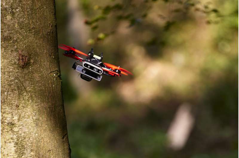
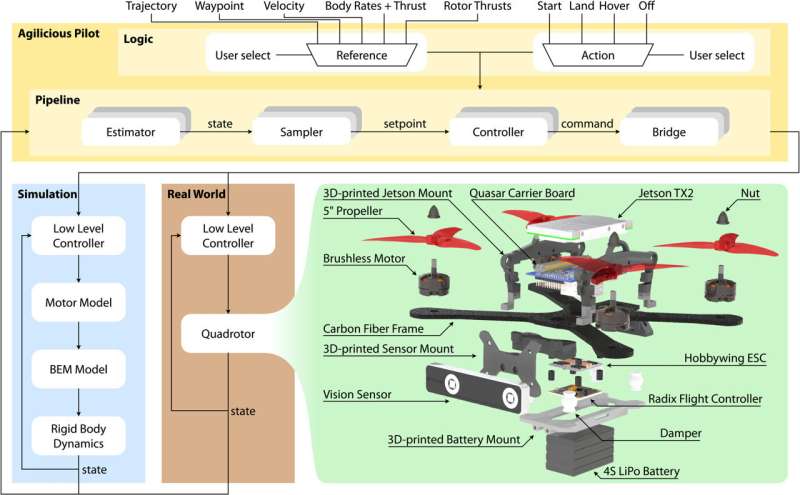
    A highly maneuverable quadrotor drone with trajectory tracking capabilities has been created by a team of researchers from the University of Zurich. The crew details how they created their drone, the components they used, and how well it performed during testing in their research that was published in the journal Science Robotics software Autonomous.

    Quadrotor drones are capable of maneuvering with great agility, especially when a human pilot is controlling them. On the other side, autonomous quadrotors have experienced problems with agility, especially when moving quickly. With their innovative design created utilizing a range of technologies, the Swiss team has increased the maneuverability of a quadrotor drone in this new endeavor.

    Open hardware and software Autonomous quadrotor maneuvers around obstacles quickly.

    The new design involved adding onboard vision sensors, monitoring systems for flight control and a host of other components meant to improve the ability of the drone to receive and process flight information in real time. They also added an advanced AI module, NVIDIA Jetson TX2—one that is able to carry out complex tasks supporting the drone’s hardware quickly enough to allow for smooth agile flight.

    The researchers tested their drone under a wide range of flights, from slow and steady, to full speed to obstacle avoidance. They found their drone capable of maintaining agility at speeds ranging from 50 to 70 kph. They also found it could conduct motion-capture trajectory tracking, where the drone continuously observes its position in the air and adds time instances to show where it is and when. They also tested its use in virtual reality simulations. And they also noted, that the system was able to learn as it went and because of that its performance improved over time.

    The researchers’ drone surpassed rival systems in terms of agility as well as obstacle tracking and avoidance, according to the testing results. They claim that because to its improved performance, it might be utilized for time-sensitive real-world tasks including delivery of commodities and search and rescue operations. To enable anyone to adopt their idea, the team has also made both the software and hardware open source.

    Read More

  • Robotic Mayflower ship arrives at Plymouth Rock without crew.

    Robotic Mayflower ship arrives at Plymouth Rock without crew.

    Robotic Mayflower ship arrives at Plymouth Rock without crew.
    Robotic Mayflower ship

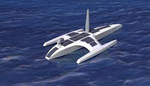
    A robotic Mayflower ship without a crew that is retracing the Mayflower’s 1620 maritime trip has docked close to Plymouth Rock.

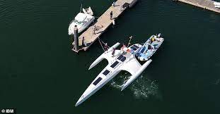
    More than 400 years after the historic voyage of its namesake from England, the svelte Mayflower Autonomous Ship greeted an escort boat as it approached the Massachusetts coastline on Thursday.

    In accordance with U.S. Coast Guard regulations for crewless vessels, it was pulled into Plymouth Harbor and moored close to a replica of the original Mayflower that carried the Pilgrims to America.

    The 50-foot (15-meter) trimaran was being driven by artificial intelligence software; there was no human captain, navigator, or crew members present.

    Technical issues prevented the solar-powered ship from making its intended transatlantic crossing in 2021, forcing it to return to Plymouth, England—the same town from which the Pilgrim colony embarked in 1620.

    In April, it departed once more from the southwest coast of England, but technical issues forced a detour to the Azores Islands in Portugal, then to Canada.

    Rob High, a software executive at IBM who is working on the project, stated that it is evident that you cannot make the necessary mechanical and physical improvements without anyone on board. That is a component of learning as well.

    Robotic Mayflower ship arrives at Plymouth Rock without crew.

    The ship was constructed by IBM and nonprofit maritime research organization ProMare, which has been using it to gather information about whales, microplastic pollution, and other scientific studies. Although there have been a few small autonomous experimental vessels that have crossed the Atlantic, this is the first ship of its size, according to researchers.

    The conclusion of the expedition “means we can start evaluating data from the ship’s journey” and investigate the effectiveness of the AI system, High said. It will be simpler to gather “all the kinds of things that marine biologists care about,” according to him, if crewless vessels of this type are expected to navigate the waters on a regular basis.

    Read More

  • Robots are guided by humans in the loop.

    Robots are guided by humans in the loop.

    Robots are guided by humans in the loop.
    Robots are guided by humans in the loop.

    Robots are guided by humans. Robots cannot see past barriers, much like humans. To reach where they’re going, they occasionally require a little assistance.

    Rice University engineers have created a technique that enables people to assist robots in “seeing” their surrounds and performing jobs.

    A unique approach to the age-old issue of motion planning for robots operating in surroundings where not everything is always clearly visible is the Bayesian Learning IN the Dark (BLIND) concept.

    Late in May, the George R. Brown School of Engineering at Rice presented the research led by computer scientists Vaibhav Unhelkar and Lydia Kavraki, as well as co-lead authors Carlos Quintero-Pea and Constantinos Chamzas, at the International Conference on Robotics and Automation of the Institute of Electrical and Electronics Engineers.

    According to the report, the program, which was principally created by graduate students Quintero-Pea and Chamzas who collaborated with Kavraki, keeps a human in the loop to “augment robot perception and, significantly, prevent the execution of unsafe motion.”

    In order to help robots that have “large degrees of freedom,” or numerous moving parts, they did this by combining Bayesian inverse reinforcement learning—a method through which a system learns from continuously updated information and experience—with tried-and-true motion planning approaches.

    The Rice lab used a Fetch robot, an articulated arm with seven joints, to test BLIND by instructing it to move across a barrier while grabbing a small cylinder from one table and moving it to another.

    According to Quintero-Pea, “instructions to the robot get complicated if you have more joints.” You only need to say, “Lift up your hand,” when directing a person.

    But when barriers obstruct the machine’s “view” of its target, a robot’s programmers must be precise about the movement of each joint at every point in its trajectory.

    BLIND inserts a human mid-process to modify the choreographic options—or best guesses—suggested by the robot’s algorithm rather than programming a trajectory in advance. In this high-degree-of-freedom space, “BLIND allows us to take information in the human head and compute our trajectories,” Quintero-Pea explained.

    We employ a particular technique of feedback called critique, which is essentially a binary form of feedback in which the human is given labels on segments of the trajectory.

    These labels appear as a series of interconnected green dots that show potential routes. The human accepts or rejects each step that BLIND takes as it moves from dot to dot in order to fine-tune the course and effectively avoid obstructions.

    Robots are guided by humans in the loop.2

    According to Chamzas, because we can tell the robot, “I like this,” or “I don’t like that,” the interface is simple for people to utilize. The robot can complete its mission after it receives approval for a set of moves, he said.

    “One of the most important things here is that human preferences are hard to describe with a mathematical formula,” Quintero-Peña said. “Our work simplifies human-robot relationships by incorporating human preferences. That’s how I think applications will get the most benefit from this work.”

    “This work wonderfully exemplifies how a little, but targeted, human intervention can significantly enhance the capabilities of robots to execute complex tasks in environments where some parts are completely unknown to the robot but known to the human,” said Kavraki, a robotics pioneer whose resume includes advanced programming for NASA’s humanoid Robonaut aboard the International Space Station.

    “It shows how methods for human-robot interaction, the topic of research of my colleague Professor Unhelkar, and automated planning pioneered for years at my laboratory can blend to deliver reliable solutions that also respect human preferences.”

    Read More

  • How to Design Smart Walking Stick with GPS, GSM and Arduino

    How to Design Smart Walking Stick with GPS, GSM and Arduino

    In today’s project tutorial, we will be discussing how to design and construct a smart walking stick with GPS capability, GSM call and SMS using Arduino. The design was made to assist blind people or people with sight defects, giving them directions as they go. In summary,

    • It uses utrasonic sensor to tell the user or blind person the direction he or she is heading to.
    • It also gives real time location to the medical personnel’s or guardians of this person about their whereabout at any particular time.
    • An emergency button is incorporated into the design such that the person can press this button whenever he or she is in distress. This would make an emergency call to the guardian or medical doctor and also send an SMS to them with he exact location of where such distress originated from.
    • The smart walking stick project has also incorporated a DC charging unit that uses 5V LiPo Battery to power the project.
    • A solar panel was used to charge the design when the battery is down.

    Read More

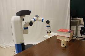
    This is a stick-based robot

    The True Prices of Delivery drones

    The Schematic Diagram

    smart waking stick

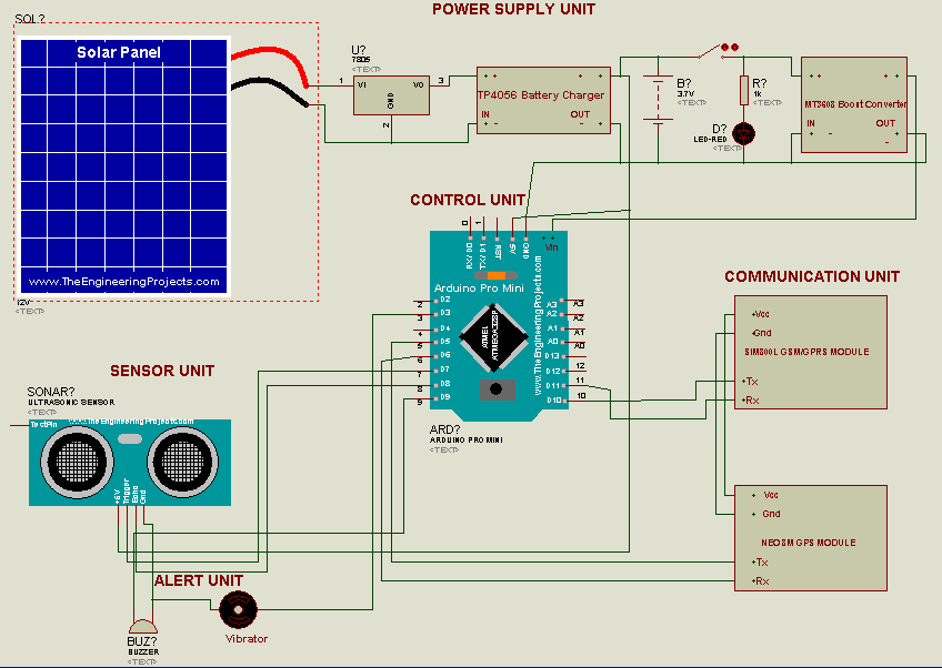
    The circuit diagram above shows the connection of the Arduino Pro-Mini board to the the rest of the peripheral components used in this project’s design.

    Smart Walking Stick Circuit Diagram Explanation

    The schematic diagram shows that the GSM module works with serial communication protocol It uses two digital wires to communicate with the Arduino Nano board, these pins on the Arduino are the digital pin 10 and 11 respectively (D10 and D11).

    The transmitter pin (Tx) of the Neo-8M GPS module is connected to digital pin 5 (D5) on the Arduino, while the receiver pin (Rx) is connected to digital pin 6 (D6) on the Arduino, respectively. Both the GPS and the GSM module are powered by 3.7V power supply.

    The sonar or ultrasonic sensor uses 2 digital pins on the Arduino too, the trig pin and the echo pins are connected to the digital pin7 and digital pin 8 on the Arduino board. While the Vcc and the GND pins are connected to the 5V power supply rails.

    Two digital pins were used to take care of the activation of the buzzers and the vibrator actuators. These actuators are activated when a digital pin on the Arduino is made HIGH. The buzzer would be to alert the user of possible obstacle in the path that is above 50cm while the vibrator warns the user about obstacle that is less than 50cm in his or her path.

    Fabricating the Arduino based Smart Walking Stick with GPS and GSM capability.

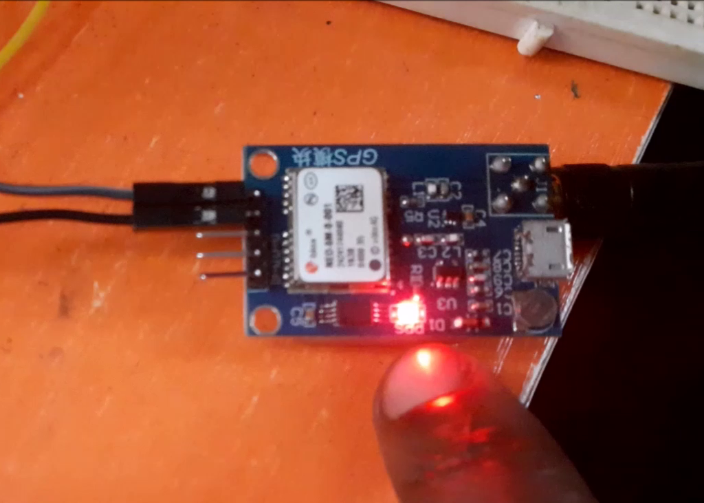
    smart walking stick: the GPS module

    The system is assembled as shown in the circuit diagram. It is then soldered and powered on. As shown above we can see the GPS module blinking every second to show that it is connected to the satellite.

    The GSM module also blinks twice every second once it has cellular reception and this was very important. Using the SIM800L as the GSM module makes it a little difficult since this module is sometimes very stubborn to get the cellular network signal required but once powered appropriately with the right voltage, it is quick to respond.

    Arduino Source Code

    #define TINY_GSM_MODEM_SIM800
    #include <TinyGPS.h>
    #define SerialMon Serial
    #include <SoftwareSerial.h>
    SoftwareSerial SerialAT(10,11); // RX, TX
    SoftwareSerial mySerial(10, 11); // RX, TX
    //#define DUMP_AT_COMMANDS
    #define TINY_GSM_DEBUG SerialMon
    
    #define SMS_TARGET  "+2348125663555" //client's number
    #define CALL_TARGET "+2348125663555"
    
    #include <TinyGsmClient.h>
    #ifdef DUMP_AT_COMMANDS
    #include <StreamDebugger.h>
    StreamDebugger debugger(SerialAT, SerialMon);
    TinyGsm modem(debugger);
    #else
    TinyGsm modem(SerialAT);
    #endif
    
    #include <Sim800l.h>
    Sim800l Sim800l;  
    
    uint8_t index;
    bool error;
    
    char* charLocation;
    String text;
    String location;
    
    #define trigPin 7
    #define echoPin 8
    #define buzzerPin 9
    #define vibratorPin 3
    
    long duration, distance;
    
    SoftwareSerial gpsModule(6,5); //GPS Module TX to Arduino PIN 10, GPS Module RX to Arduino PIN 11
    TinyGPS gps;
    void(* resetFunc) (void) = 0;  // declare reset fuction at address 0
    int pwr = 5;
    void gpsdump(TinyGPS &gps);
    void printFloat(double f, int digits = 2);
    String latitudeValue;
    String longitudeValue;
    
    void setup() 
    {
      Sim800l.begin();
      SerialAT.begin(9600);
      SerialMon.begin(9600);
      pinMode(trigPin, OUTPUT);
      pinMode(echoPin, INPUT);
      pinMode(buzzerPin, OUTPUT);
      pinMode(vibratorPin, OUTPUT);
      mySerial.begin(115200);
      gpsModule.begin(9600);
      delay(500);
    }
    
    void loop() 
    {
      checkObstacle();
    
      if(distance>30)
      {
        digitalWrite(buzzerPin,LOW);  
        digitalWrite(vibratorPin,LOW);  
      }
    
      else if(distance>20&&distance<30)
      {
        digitalWrite(vibratorPin,HIGH); 
        digitalWrite(buzzerPin,HIGH);  
        delay(500);
        digitalWrite(buzzerPin,LOW); 
        delay(500);
    
        digitalWrite(buzzerPin,HIGH);  
        delay(500);
        digitalWrite(buzzerPin,LOW); 
        delay(500);
    
        digitalWrite(buzzerPin,HIGH);  
        delay(500);
        digitalWrite(buzzerPin,LOW); 
        delay(1000);
        
      }
    
      else if(distance>10&&distance<20)
      {
        digitalWrite(vibratorPin,HIGH); 
        digitalWrite(buzzerPin,HIGH);  
        delay(500);
        digitalWrite(buzzerPin,LOW); 
        delay(500);
    
        digitalWrite(buzzerPin,HIGH);  
        delay(500);
        digitalWrite(buzzerPin,LOW); 
        delay(1000); 
      }
    
      else if(distance<10)
      {
        digitalWrite(buzzerPin,HIGH); 
        digitalWrite(vibratorPin,HIGH); 
        call();
        sendSMS();
      }
    
      else
      {
        digitalWrite(buzzerPin,LOW);  
        digitalWrite(vibratorPin,LOW); 
      }
    }
    
    double checkObstacle()
    {
      digitalWrite(trigPin, LOW);
      delayMicroseconds(2);
      digitalWrite(trigPin, HIGH);
      delayMicroseconds(10);
      digitalWrite(trigPin, LOW);
      duration = pulseIn(echoPin, HIGH);
      distance = (duration/2) / 29.1;
    }
    
    void call()
    {
      boolean res1 = modem.callNumber(CALL_TARGET);
      
      if (res1) 
      {
        delay(1000L);
        // Play DTMF A, duration 1000ms
        modem.dtmfSend('A', 1000);
    
        // Play DTMF 0...4, default duration (100ms)
        for (char tone='0'; tone<='4'; tone++) 
        {
          modem.dtmfSend(tone);
        }
        
        delay(30000);
        res1 = modem.callHangup();
      }                                                                                                                                                                                                                                                                                                                                                                                                                                                                   
    }
    
    void sendSMS()
    {
      #if defined(SMS_TARGET)  
      // This is only supported on SIMxxx series
      boolean res = modem.sendSMS_UTF16(SMS_TARGET, u"ALERT! The visually impaired person has possibly hit an obstacle. Please, call him IMMEDIATELY!", 95);
      #endif
    }
    
    void loop() // run over and over
    {
      mySerial.println("AT+CMGF=1"); //Read SIM information to confirm whether the SIM is plugged
      updateSerial();
      mySerial.println("AT+CNMI=1,2,0,0,0"); //Read SIM information to confirm whether the SIM is plugged
      updateSerial();
    }
    
    void initModule(String cmd, char *res, int t) 
    {
      while (1)
      {
        Serial.println(cmd);
        mySerial.println(cmd);
        delay(1000);
        while (mySerial.available() > 0)
        {
          if (mySerial.find(res))
          {
            mySerial.println(res);
            delay(t);
            return;
          }
    
          else
          {
            mySerial.println("Error");
          }
        }
        delay(t);
      }
    }
    
    void gpsdump(TinyGPS &gps)
    {
      long lat, lon;
      float flat, flon;
      unsigned long age;
    
      gps.f_get_position(&flat, &flon, &age);
      //
      latitudeValue = String(flat, 5);
      longitudeValue = String(flon, 5);
      //
      Serial.println("Latitude: " + latitudeValue + ", Longitude: " + longitudeValue);
      //
    }
    
    
    void sms()
    {
      mySerial.println("AT"); //Once the handshake test is successful, it will back to OK
      //  updateSerial();
       //mySerial.println("AT+CSQ"); //Signal quality test, value range is 0-31 , 31 is the best
      updateSerial();
      mySerial.println("AT+CMGF=1"); //Signal quality test, value range is 0-31 , 31 is the best
      updateSerial();
      mySerial.println("AT+CNMI=2,1,0,0,0"); //Read SIM information to confirm whether the SIM is plugged
      updateSerial();
      mySerial.println("AT+CMGS=\"08125663555\"\r\n"); //Check whether it has registered in the network
      updateSerial();
      mySerial.println("http://www.google.com/maps/place/" + latitudeValue + "," + longitudeValue );
        mySerial.write(26); 
      mySerial.println("AT+CMGDA=\"DEL ALL\"\r\n");
                                          // Ctrl-Z indicates end of SMS    
      delay(100);  
    //   resetFunc(); // wait for a 500ms delay
    }
    
      void updateSerial()
      {  
        while (Serial.available()) 
        {
          mySerial.write(Serial.read());//Forward what Serial received to Software Serial Port
        }
        while(mySerial.available()) 
        {
          Serial.write(mySerial.read());//Forward what Software Serial received to Serial Port
        }
      }
      
     void LOC()
     {  
      bool newdata = false;
      unsigned long start = millis();
      // Every 5 seconds we print an update
      while (millis() - start < 5000) 
      {
        if (gpsModule.available()) 
        {
          char c = gpsModule.read();
          //Serial.print(c);  // uncomment to see raw GPS data
          if (gps.encode(c)) 
          {
            newdata = true;
            break;  // uncomment to print new data immediately!
          }
        }
        } 
      if (newdata) 
      {
        //New GPS Data Received
        gpsdump(gps); 
        sms();
      }
      else
      {
        //No New GPS Data Received
        Serial.println("Latitude: " + latitudeValue + ", Longitude: " + longitudeValue);
        //
      }
    }


    The Result

    smart walking stick project
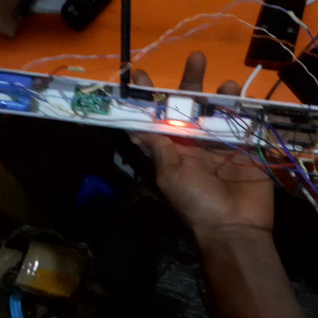
    encasing the whole design and wiring in a PVC pipe

    The system design in all encases in a PVC pipe used for insulating or conduit wiring. It was strong and durable and provided what was needed for the smart walking stick project.

    Conclusion

    The Smart walking stick project with GPS, call and SMS capabilities to be charged and later use, this means that the project is rechargeable. It can alert the user’s guardian’s about the user real-time whereabout, also notify the user how far and obstacle is from him or her. Let us know if the project was able to assist you.

  • educating a robot to identify and pour water

    educating a robot to identify and pour water

    educating a robot to identify and pour water
    educating a robot to identify and pour water

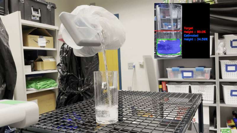
    Researchers at Carnegie Mellon University were able to teach a robot to recognize water and pour it into a glass with the help of a horse, a zebra, and artificial intelligence.

    Robots face a difficult issue since water is transparent. Robots have previously learned to pour water, but earlier methods like heating the water and using a thermal camera or setting the glass in front of a checkerboard background don’t work well in real-world situations. Robot waitresses might refill water glasses, robot pharmacists could measure and mix medications, and robot gardeners could water plants as part of a simpler approach.

    In the Robots Perceiving and Doing Lab of the Robotics Institute, Gautham Narasimhan collaborated with a group to apply AI and image translation to resolve the issue. Gautham Narasimhan graduated from the Robotics Institute in 2020 with a master’s degree.

    To educate artificial intelligence to change images from one style to another, such as turning a photograph into a Monet-style painting or changing an image of a horse into a zebra, mage translation algorithms use libraries of images. Contrastive learning for unpaired image-to-image translation was the technique employed by the team for this study (CUT, for short).

    David Held, an assistant professor of the Robotics Institute who counseled Narasimhan, noted that during the training phase of learning, “You need some method of notifying the algorithm what the right and wrong answers are.” However, labeling data can be a laborious procedure, particularly when training a robot to pour water, for which a person may need to name specific water droplets in an image.

    “Just like we can train a model to translate an image of a horse to look like a zebra, we can similarly train a model to translate an image of colored liquid into an image of transparent liquid,” Held said. “We used this model to enable the robot to understand transparent liquids.”

    A transparent liquid like water is hard for a robot to see because the way it reflects, refracts and absorbs light varies depending on the background. To teach the computer how to see different backgrounds through a glass of water, the team played YouTube videos behind a transparent glass full of water. Training the system this way will allow the robot to pour water against varied backgrounds in the real world, regardless of where the robot is located.

    Even for humans, Narasimhan noted, “there are moments when it can be challenging to accurately define the boundary between water and air.”

    Their technique allowed the robot to fill a glass with water to a specific height. The experiment was then carried out once more using glasses of various sizes and shapes.

    Future study could improve upon this approach, according to Narasimhan, by incorporating varying lighting conditions, having the robot attempt to pour water from one container to another, or assessing both the height and amount of the water.

    The study was presented last month in Philadelphia at the IEEE International Conference on Robotics and Automation. Reaction to the work has been positive, Narasimhan said.

    “People in the robotics community really appreciate it when research works in the real world and not only in simulation,” said Narasimhan, who is currently employed by Path Robotics in Columbus, Ohio, as a computer vision engineer. “We wanted to do something that was straightforward yet still had impact.

    Read More