In today’s project tutorial, we will be discussing how to design and construct a smart walking stick with GPS capability, GSM call and SMS using Arduino. The design was made to assist blind people or people with sight defects, giving them directions as they go. In summary,
- It uses utrasonic sensor to tell the user or blind person the direction he or she is heading to.
- It also gives real time location to the medical personnel’s or guardians of this person about their whereabout at any particular time.
- An emergency button is incorporated into the design such that the person can press this button whenever he or she is in distress. This would make an emergency call to the guardian or medical doctor and also send an SMS to them with he exact location of where such distress originated from.
- The smart walking stick project has also incorporated a DC charging unit that uses 5V LiPo Battery to power the project.
- A solar panel was used to charge the design when the battery is down.
Read More
The True Prices of Delivery drones
The Schematic Diagram
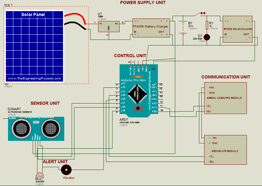
The circuit diagram above shows the connection of the Arduino Pro-Mini board to the the rest of the peripheral components used in this project’s design.
Smart Walking Stick Circuit Diagram Explanation
The schematic diagram shows that the GSM module works with serial communication protocol It uses two digital wires to communicate with the Arduino Nano board, these pins on the Arduino are the digital pin 10 and 11 respectively (D10 and D11).
The transmitter pin (Tx) of the Neo-8M GPS module is connected to digital pin 5 (D5) on the Arduino, while the receiver pin (Rx) is connected to digital pin 6 (D6) on the Arduino, respectively. Both the GPS and the GSM module are powered by 3.7V power supply.
The sonar or ultrasonic sensor uses 2 digital pins on the Arduino too, the trig pin and the echo pins are connected to the digital pin7 and digital pin 8 on the Arduino board. While the Vcc and the GND pins are connected to the 5V power supply rails.
Two digital pins were used to take care of the activation of the buzzers and the vibrator actuators. These actuators are activated when a digital pin on the Arduino is made HIGH. The buzzer would be to alert the user of possible obstacle in the path that is above 50cm while the vibrator warns the user about obstacle that is less than 50cm in his or her path.
Fabricating the Arduino based Smart Walking Stick with GPS and GSM capability.
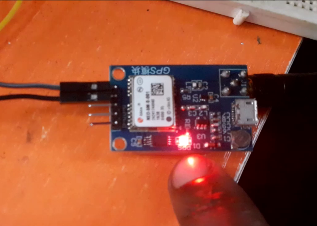
The system is assembled as shown in the circuit diagram. It is then soldered and powered on. As shown above we can see the GPS module blinking every second to show that it is connected to the satellite.
The GSM module also blinks twice every second once it has cellular reception and this was very important. Using the SIM800L as the GSM module makes it a little difficult since this module is sometimes very stubborn to get the cellular network signal required but once powered appropriately with the right voltage, it is quick to respond.
Arduino Source Code
#define TINY_GSM_MODEM_SIM800
#include <TinyGPS.h>
#define SerialMon Serial
#include <SoftwareSerial.h>
SoftwareSerial SerialAT(10,11); // RX, TX
SoftwareSerial mySerial(10, 11); // RX, TX
//#define DUMP_AT_COMMANDS
#define TINY_GSM_DEBUG SerialMon

#define SMS_TARGET  "+2348125663555" //client's number
#define CALL_TARGET "+2348125663555"

#include <TinyGsmClient.h>
#ifdef DUMP_AT_COMMANDS
#include <StreamDebugger.h>
StreamDebugger debugger(SerialAT, SerialMon);
TinyGsm modem(debugger);
#else
TinyGsm modem(SerialAT);
#endif

#include <Sim800l.h>
Sim800l Sim800l;

uint8_t index;
bool error;

char* charLocation;
String text;
String location;

#define trigPin 7
#define echoPin 8
#define buzzerPin 9
#define vibratorPin 3

long duration, distance;

SoftwareSerial gpsModule(6,5); //GPS Module TX to Arduino PIN 10, GPS Module RX to Arduino PIN 11
TinyGPS gps;
void(* resetFunc) (void) = 0;  // declare reset fuction at address 0
int pwr = 5;
void gpsdump(TinyGPS &gps);
void printFloat(double f, int digits = 2);
String latitudeValue;
String longitudeValue;

void setup()
{
  Sim800l.begin();
  SerialAT.begin(9600);
  SerialMon.begin(9600);
  pinMode(trigPin, OUTPUT);
  pinMode(echoPin, INPUT);
  pinMode(buzzerPin, OUTPUT);
  pinMode(vibratorPin, OUTPUT);
  mySerial.begin(115200);
  gpsModule.begin(9600);
  delay(500);
}

void loop()
{
  checkObstacle();

  if(distance>30)
  {
    digitalWrite(buzzerPin,LOW);
    digitalWrite(vibratorPin,LOW);
  }

  else if(distance>20&&distance<30)
  {
    digitalWrite(vibratorPin,HIGH);
    digitalWrite(buzzerPin,HIGH);
    delay(500);
    digitalWrite(buzzerPin,LOW);
    delay(500);

    digitalWrite(buzzerPin,HIGH);
    delay(500);
    digitalWrite(buzzerPin,LOW);
    delay(500);

    digitalWrite(buzzerPin,HIGH);
    delay(500);
    digitalWrite(buzzerPin,LOW);
    delay(1000);

  }

  else if(distance>10&&distance<20)
  {
    digitalWrite(vibratorPin,HIGH);
    digitalWrite(buzzerPin,HIGH);
    delay(500);
    digitalWrite(buzzerPin,LOW);
    delay(500);

    digitalWrite(buzzerPin,HIGH);
    delay(500);
    digitalWrite(buzzerPin,LOW);
    delay(1000);
  }

  else if(distance<10)
  {
    digitalWrite(buzzerPin,HIGH);
    digitalWrite(vibratorPin,HIGH);
    call();
    sendSMS();
  }

  else
  {
    digitalWrite(buzzerPin,LOW);
    digitalWrite(vibratorPin,LOW);
  }
}

double checkObstacle()
{
  digitalWrite(trigPin, LOW);
  delayMicroseconds(2);
  digitalWrite(trigPin, HIGH);
  delayMicroseconds(10);
  digitalWrite(trigPin, LOW);
  duration = pulseIn(echoPin, HIGH);
  distance = (duration/2) / 29.1;
}

void call()
{
  boolean res1 = modem.callNumber(CALL_TARGET);

  if (res1)
  {
    delay(1000L);
    // Play DTMF A, duration 1000ms
    modem.dtmfSend('A', 1000);

    // Play DTMF 0...4, default duration (100ms)
    for (char tone='0'; tone<='4'; tone++)
    {
      modem.dtmfSend(tone);
    }

    delay(30000);
    res1 = modem.callHangup();
  }
}

void sendSMS()
{
  #if defined(SMS_TARGET)
  // This is only supported on SIMxxx series
  boolean res = modem.sendSMS_UTF16(SMS_TARGET, u"ALERT! The visually impaired person has possibly hit an obstacle. Please, call him IMMEDIATELY!", 95);
  #endif
}

void loop() // run over and over
{
  mySerial.println("AT+CMGF=1"); //Read SIM information to confirm whether the SIM is plugged
  updateSerial();
  mySerial.println("AT+CNMI=1,2,0,0,0"); //Read SIM information to confirm whether the SIM is plugged
  updateSerial();
}

void initModule(String cmd, char *res, int t)
{
  while (1)
  {
    Serial.println(cmd);
    mySerial.println(cmd);
    delay(1000);
    while (mySerial.available() > 0)
    {
      if (mySerial.find(res))
      {
        mySerial.println(res);
        delay(t);
        return;
      }

      else
      {
        mySerial.println("Error");
      }
    }
    delay(t);
  }
}

void gpsdump(TinyGPS &gps)
{
  long lat, lon;
  float flat, flon;
  unsigned long age;

  gps.f_get_position(&flat, &flon, &age);
  //
  latitudeValue = String(flat, 5);
  longitudeValue = String(flon, 5);
  //
  Serial.println("Latitude: " + latitudeValue + ", Longitude: " + longitudeValue);
  //
}


void sms()
{
  mySerial.println("AT"); //Once the handshake test is successful, it will back to OK
  //  updateSerial();
   //mySerial.println("AT+CSQ"); //Signal quality test, value range is 0-31 , 31 is the best
  updateSerial();
  mySerial.println("AT+CMGF=1"); //Signal quality test, value range is 0-31 , 31 is the best
  updateSerial();
  mySerial.println("AT+CNMI=2,1,0,0,0"); //Read SIM information to confirm whether the SIM is plugged
  updateSerial();
  mySerial.println("AT+CMGS=\"08125663555\"\r\n"); //Check whether it has registered in the network
  updateSerial();
  mySerial.println("http://www.google.com/maps/place/" + latitudeValue + "," + longitudeValue );
    mySerial.write(26);
  mySerial.println("AT+CMGDA=\"DEL ALL\"\r\n");
                                      // Ctrl-Z indicates end of SMS
  delay(100);
//   resetFunc(); // wait for a 500ms delay
}

  void updateSerial()
  {
    while (Serial.available())
    {
      mySerial.write(Serial.read());//Forward what Serial received to Software Serial Port
    }
    while(mySerial.available())
    {
      Serial.write(mySerial.read());//Forward what Software Serial received to Serial Port
    }
  }

 void LOC()
 {
  bool newdata = false;
  unsigned long start = millis();
  // Every 5 seconds we print an update
  while (millis() - start < 5000)
  {
    if (gpsModule.available())
    {
      char c = gpsModule.read();
      //Serial.print(c);  // uncomment to see raw GPS data
      if (gps.encode(c))
      {
        newdata = true;
        break;  // uncomment to print new data immediately!
      }
    }
    }
  if (newdata)
  {
    //New GPS Data Received
    gpsdump(gps);
    sms();
  }
  else
  {
    //No New GPS Data Received
    Serial.println("Latitude: " + latitudeValue + ", Longitude: " + longitudeValue);
    //
  }
}
The Result
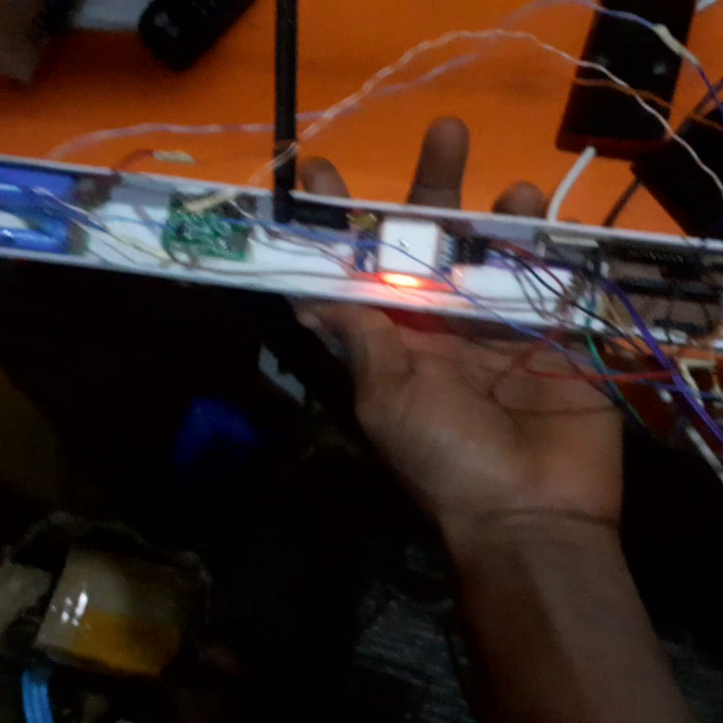
The system design in all encases in a PVC pipe used for insulating or conduit wiring. It was strong and durable and provided what was needed for the smart walking stick project.
Conclusion
The Smart walking stick project with GPS, call and SMS capabilities to be charged and later use, this means that the project is rechargeable. It can alert the user’s guardian’s about the user real-time whereabout, also notify the user how far and obstacle is from him or her. Let us know if the project was able to assist you.