In this project, we will measure the direct current (DC) voltage in our power supply using the software and hardware serial connections with the ESP8266-01 and Arduino, as well as monitor it on the Blynk IoT platform. This project is mainly called the IOT (Internet of Things) process.
The following materials are used in this project:
- Arduino Unno
- ESP8266-01
- Blynk Application.
- Voltage Sensors
- Power Supply(3.3v, 5v, 12v and 23v)
You can buy the complete kit of this tutorial on our online store. If any of the components or kits is not complete, you can chat us and request for it.
What is ESP8266-01?

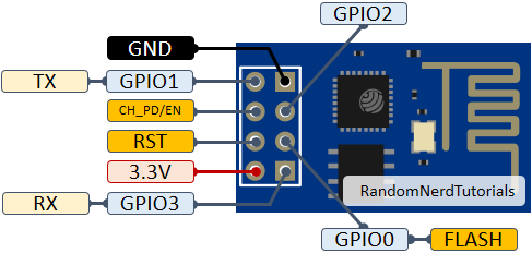
The ESP8266-01 (ESP-01) is a Wi-Fi module that allows microcontrollers access to a Wi-Fi network. This ESP8266-01 helped in the IoT monitoring of our project. It has 8 pins, which consist of RXD, TXD, GND, VCC, RST, GPIO0, GPIO1, and EN, respectively. In which RXD – is the Receiver, TXD – is the Transmitter. The maximum voltage expected for the ESP8266-01 is 3.3V.
HOW TO CONNECT ESP8266-01 TO ARDUINO UNO.
There are different connections when connecting the Arduino with the ESP8266-01, These are:
- Hardware Serial Connection
- Software Serial Connection
Hardware Serial Connection
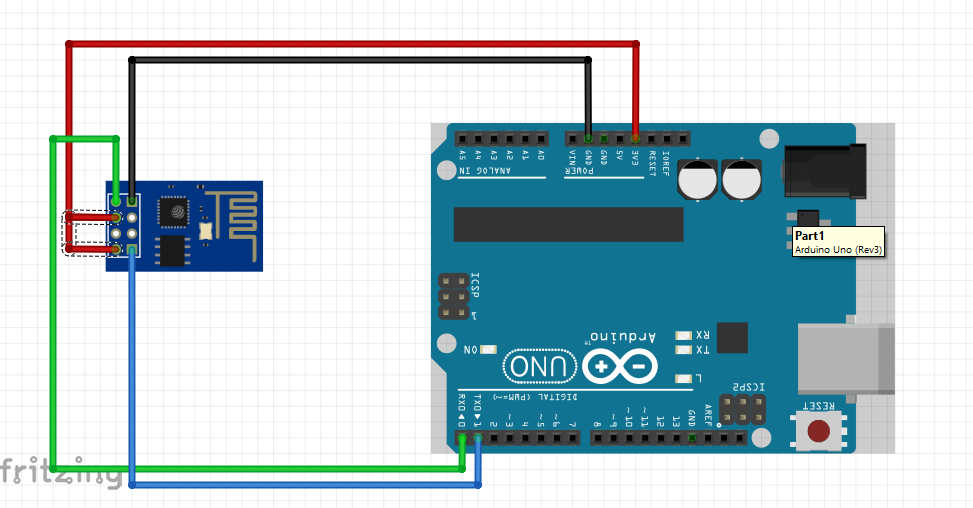
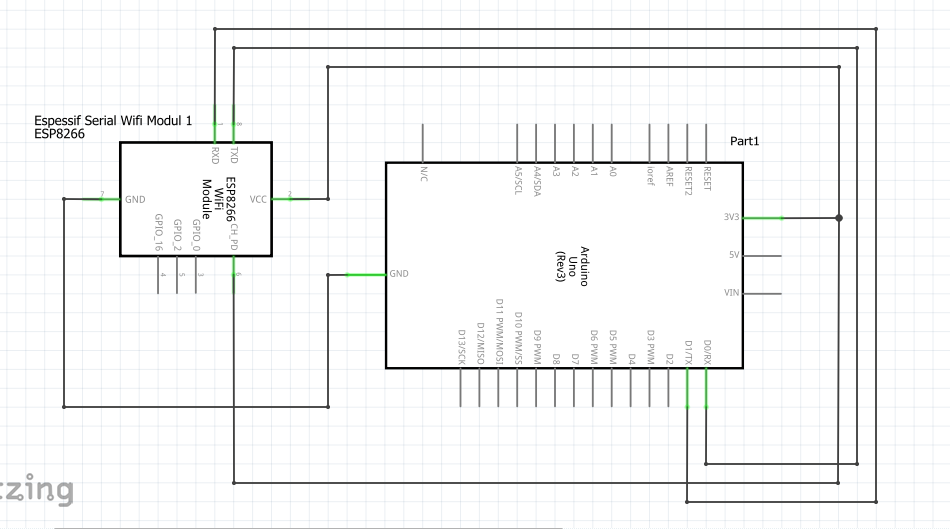
This involves connecting the RX and TX of the ESP-01 with the TX and RX of the Arduino Uno respectively.
CONNECTION FORMAT BETWEEN ESP8266-01 AND ARDUINO UNO
| ESP 8266 -01 | ARDUINO UNO |
| RX | TX |
| TX | RX |
Software Serial Connection
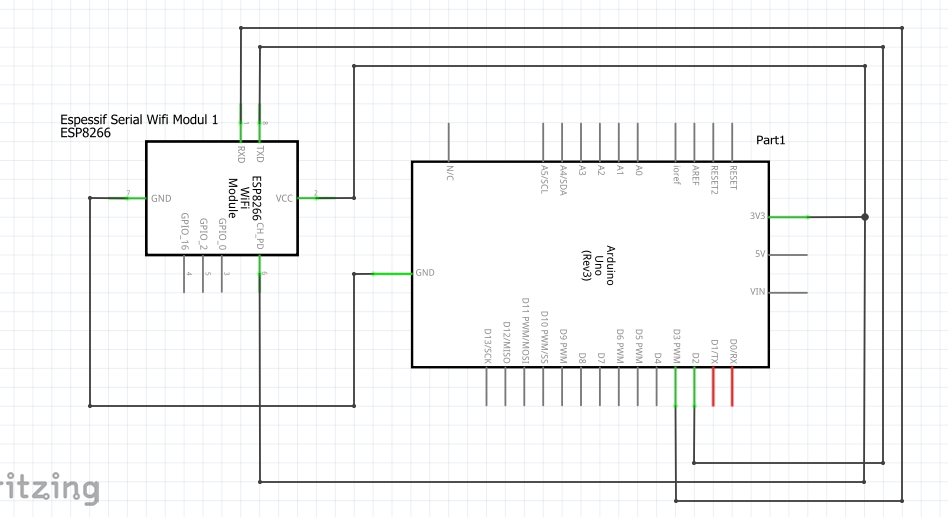
This Involves connecting the RX and TX of the ESP-01 to any Digital Pins on the Arduino respectively. For my connection, I will be working with Digital Pin 2 and 3 that is D2 and D3 respectively.
CONNECTION FORMAT BETWEEN ESP8266-01 AND ARDUINO UNO
| ESP 8266 -01 | ARDUINO UNO |
| RX | D2 |
| TX | D3 |
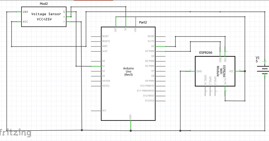
As stated above, on the ESP8266-01 which has 8 pins, The Vcc and EN of ESP-01 is connected to Arduino’s 3.3V. And the RX and TX can be connected using either Hardware Serial connection or Software Serial Connection. And the ESP-01 GND which is connected to the GND of the Arduino.
How to Measure Power Supply voltage with Arduino
HOW TO CONNECT POWER SUPPLY WITH VOLTAGE SENSOR WITH ARDUINO AND ESP8266-01.
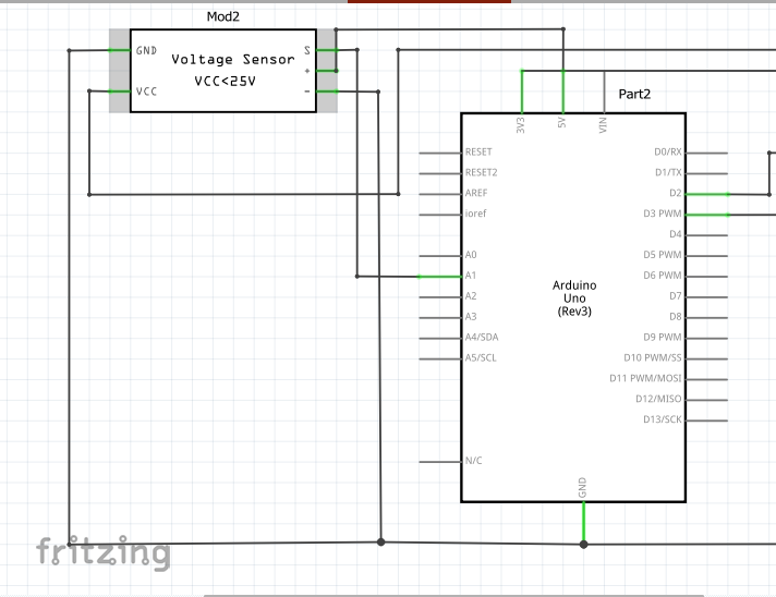
We can measure the voltage on Our DC Power Supply (3V, 5V, 9V and 12V) using the Voltage Sensor with Arduino Uno and ESP8266-01. The power supply Positive and Negative terminal is connected to the Output of the Voltage Sensor.
The Arduino Sketch
float PVr1 = 30000.0;
float PVr2 = 7500.0;
float batteryVoltSensor, vinBattery;
const int voltagePinBattery = A0;
void setup() {
Serial.begin(9600);
}
void loop(){
//now doing calculations
batteryVoltSensor = analogRead(voltagePinBattery);
batteryVoltSensor = (batteryVoltSensor * 5.0)/1023.0;
vinBattery = batteryVoltSensor/(PVr2/(PVr1+PVr2));
Serial.print("Dc Measured Voltage : ");
Serial.println(vinBattery);
delay(1000);
}
float PVr1 = 30000.0;
float PVr2 = 7500.0;
float batteryVoltSensor, vinBattery;
const int voltagePinBattery = A1;
void setup() {
Serial.begin(9600);
}
void loop(){
//now doing calculations
batteryVoltSensor = analogRead(voltagePinBattery);
batteryVoltSensor = (batteryVoltSensor * 5.0)/1023.0;
vinBattery = batteryVoltSensor/(PVr2/(PVr1+PVr2));
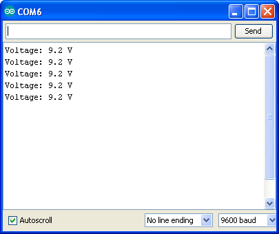
Serial.print("Voltage : ");
Serial.println(vinBattery);
delay(1000);
}
The reading of the voltage measure can be shown on the Serial Monitor of the Arduino IDE.
Then the 3 pins on the Voltage Sensors are connected to the 5V(VCC), GND and an Analog pin 1 (A1) of the Arduino respectively while the ESP8266-01 pins are expected to have a common ground in the Arduino, the Vcc is connected to 3.3V of the Arduino and the RX and TX pins are connected either via Hardware serial connection or Software serial connection.
IOT MEASURING/MONITORING OF THE POWER SUPPLY VOLTAGE
In this phase of the project, we will be using the Blynk application.
What is Blynk Application?
Blynk is an IoT platform for iOS or Android smartphones that is used to control Arduino, Raspberry Pi and NodeMCU via the Internet. This application is used to create a graphical interface or human machine interface (HMI) by compiling and providing the appropriate address on the available widgets. We used the Blynk 2.0 version here.

Monitoring Power Supply Remotely
For us to display the DC voltage that was measured or displayed from our serial monitor via IoT, we need to sign up for an account with Blynk.
Sign Up on Blynk IoT Platform
Add a new Template on Blynk
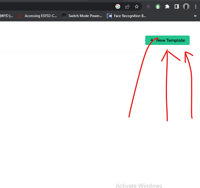
Once the sign up is successful and we are inside the dashboard, we locate the template tab and click on “add template”.
It will open an input where you can out the name of the project. Select ESP8266 and select WiFi as the connection type.
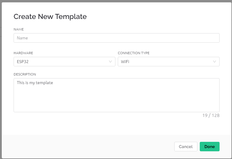
Configure Your Blynk Template
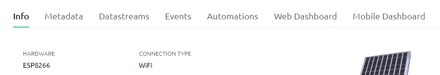
You can put in the description or just proceed to click done. Once this is done, the template would open up more tabs, this would be the Info, Metadata, DataStreams, Events, Automation, Web Dashboard and Mobile Dashboard. You can also add an image to the template if you so wishes to.
Under the Metadata, we have various infomation about the project as shown below.
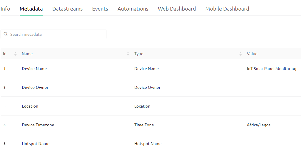
However the focus is the Datastreams
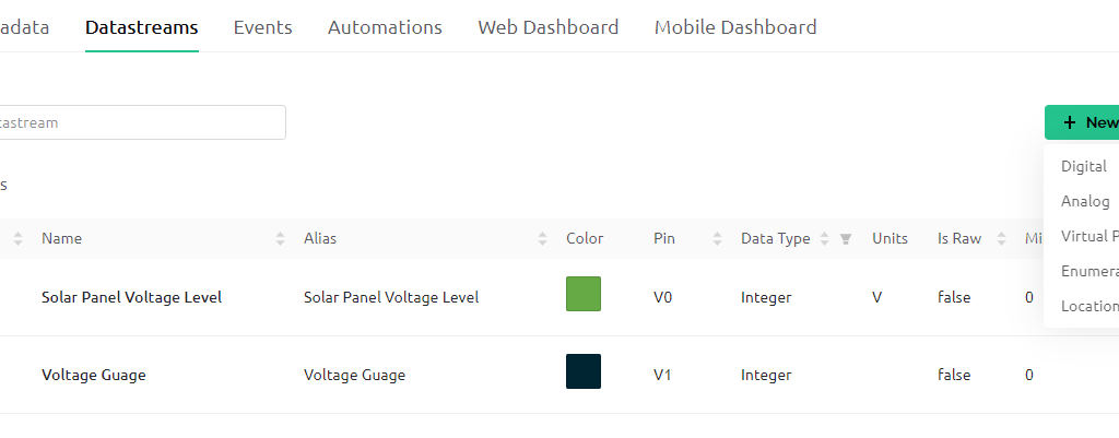
we can add a new datastreams which could measure analog, digital, virtual or enumerate as well as tell location.
Next we jump to Web Dashboard and in there we can select and set our widgets that we want to use. Fo r the purpose of this project, we just use the Guage. On the left hand side is the widget selection pane. Alternatively, one can scroll down and select the the widget Guage.
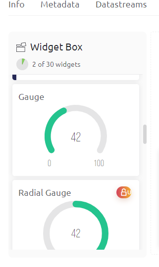
You can enlarge this guage by clicking on the expansion drag and move on the guage. You ca also chage the name from gauge to anything other name you want. Just hover over it, click on the settings that loos like a cog gear on it.
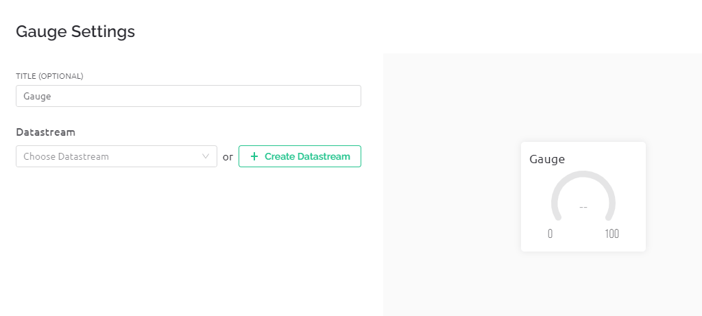
Click on the dropdown of datastream and select the project you are working with. After this, click save and leave. You are done with the Web based side. You can then download the Blynk app and set up the mobile version.
Create A Device on Blynk
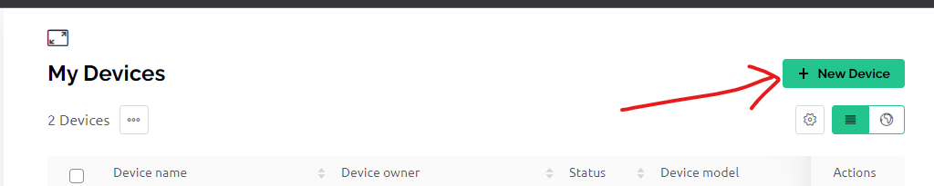
Click on the search icon and under My Devices, click on New Device. Name your device and connect it to the template. Once this is done, copy the firmware configuration code, and keep it handy.
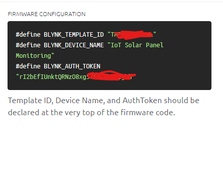
Arduino Code (Arduino Sketch)
// Template ID, Device Name and Auth Token are provided by the Blynk.Cloud
// See the Device Info tab, or Template settings
#define BLYNK_TEMPLATE_ID "TMPLqDo2lSeL"
#define BLYNK_DEVICE_NAME "IoT Solar Panel Monitoring"
#define BLYNK_AUTH_TOKEN "rI2bEfIUnktQRNzO8xg5Ti9swbEWUjhh"


// Comment this out to disable prints and save space
#define BLYNK_PRINT Serial

float PVr1 = 30000.0;
float PVr2 = 7500.0;
float batteryVoltSensor, vinBattery;
const int voltagePinBattery = A1;

#include <ESP8266_Lib.h>
#include <BlynkSimpleShieldEsp8266.h>

char auth[] = BLYNK_AUTH_TOKEN;

// Your WiFi credentials.
// Set password to "" for open networks.
char ssid[] = "AncII";
char pass[] = "helloworld@23";

// Hardware Serial on Mega, Leonardo, Micro...
//#define EspSerial Serial1

// or Software Serial on Uno, Nano...
#include <SoftwareSerial.h>
SoftwareSerial EspSerial(2, 3); // RX, TX

// Your ESP8266 baud rate:
#define ESP8266_BAUD 115200  //9600 //115200

ESP8266 wifi(&EspSerial);

BlynkTimer timer;

// This function sends Arduino's up time every second to Virtual Pin (5).
// In the app, Widget's reading frequency should be set to PUSH. This means
// that you define how often to send data to Blynk App.
void myTimerEvent(){
 //now doing calculations
  batteryVoltSensor = analogRead(voltagePinBattery);
 batteryVoltSensor = (batteryVoltSensor * 5.0)/1023.0;
 vinBattery = batteryVoltSensor/(PVr2/(PVr1+PVr2));
Serial.print("DC Measured Voltage : ");
Serial.println(vinBattery);
 delay(1000);
  Blynk.virtualWrite(V0, vinBattery);
  Serial.println(millis() / 1000);
}

void setup()
{
  // Debug console
  Serial.begin(115200);

  // Set ESP8266 baud rate
  EspSerial.begin(ESP8266_BAUD);
  delay(10);

  Blynk.begin(auth, wifi, ssid, pass);
  // You can also specify server:
  //Blynk.begin(auth, wifi, ssid, pass, "blynk.cloud", 80);
  //Blynk.begin(auth, wifi, ssid, pass, IPAddress(192,168,1,100), 8080);

  // Setup a function to be called every second
  timer.setInterval(1000L, myTimerEvent);
}

void loop(){
  Blynk.run();
  timer.run(); // Initiates BlynkTimer
}
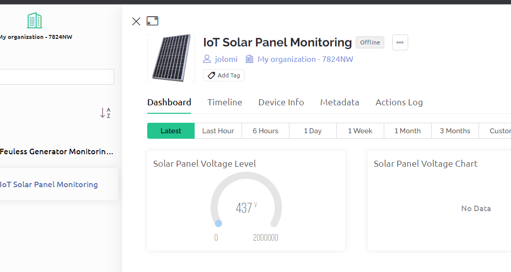
Results
Conclusion
We have been able to measure the various voltage levels of power supply ranging from 3.3V to 23V using the voltage sensor module, Arduino with EPS8266-01; and that has given us the capability to display on an IoT dashboard that can monitored and viewed from anywhere around the globe.
Let us know what you think by leaving us a comment in the comment section below. Were you able to recreate the same project following these steps?
Read More:
IoT Light Bulb – Remote Control Light Bulb Blynk App
New Discovery Drugs Could Block Protein that Ensures Bowel Cancer Growth

