The aim of this RFID home security system is to build an RFID-automated home control system using RFID technology. RFID utilizes a little radio-frequency transponder called a RF tag. The tag is electronically customized with unique data, which can be read wirelessly from a short distance. This provides a secure and peaceful environment to the people. The design will use RFID tags, RF readers with inbuilt antennas, microcontrollers, and added smart display properties to identify and track home appliances. Such that, with the use of these readers, the system is able to successfully accommodate users with approved access to preset conditions and create a secure environment which also provides convenience to the users and a significant cut down to energy waste due to the inactions of users over the home appliances. So let us go through together how to build an RFID automated home control system.
RFID (Radio Frequency Identification) technology has revolutionized various industries, and home automation is no exception. By integrating RFID into your home control system, you can create a convenient, secure, and efficient living environment. Let us understand RFID technology a little bit more than the surface.
Importance of RFID in Home Automation
RFID technology offers several advantages in home automation systems:
- Non-contact operation: RFID tags can be read without physical contact, making them ideal for remote control and automation applications.
- Durability: RFID tags are durable and can withstand harsh environmental conditions, ensuring reliable operation over time.
- Security: RFID systems can be designed with robust security measures to prevent unauthorized access and tampering.
- Versatility: RFID tags can be used to identify and track a wide range of objects, from keys and access cards to appliances and personal belongings.
Why RFID is Needed in Control Systems
RFID technology provides several key benefits in home control systems:
- Access control: RFID tags can be used to grant or deny access to specific areas of your home, such as doors, gates, and security systems.
- Automation: RFID tags can trigger automated actions, such as turning on lights, adjusting temperature, or activating appliances.
- Inventory management: RFID can be used to track the location and status of items within your home, such as appliances, tools, or valuables.
- Personalization: RFID tags can be used to personalize your home environment based on individual preferences and needs.
Security of RFID Technology
While RFID technology is generally secure, it is essential to implement appropriate measures to protect against potential vulnerabilities:
- Encryption: Use encryption algorithms to protect sensitive data transmitted between RFID tags and readers.
- Authentication: Implement authentication protocols to verify the identity of RFID tags and readers.
- Physical security: Protect RFID readers and tags from physical tampering or unauthorized access.
- Regular updates: Keep your RFID system software and firmware up-to-date to address security vulnerabilities.
Materials for the Project Design
- power supply of rating 5V, ≥2A or learn how to build your own linear PS here…1pcs
- perforated boards(line version)…..2pcs
- Light Emitting Diodes(LEDs)…….5pcs
- Light Emitting Diode (LEDs) various colors……………6pcs
- Current limiting resistor (5 color bands preferably):
- 10kΩ……5pcs
- 20 kΩ ……2pcs
- 56OΩ precision resistor
- 10KΩ potentiometer (trimmer)
- Atmega328p-pu Microcontroller…………….2pcs
- 16 MHz Crystal Oscillator……………………………2pcs
- Reset Push button………………………..1pcs
- RFID- RC522 Module……………………………………….1pcs
- RC522 cards and tags……………………….4pcs
- 5V 4-channel relay module……………………………1pcs
- 16×2 Liquid Crystal Display (LCD)…….1pcs
- LCD connector wires’
- Header pins
- Solder………..1pcs
- Soldering Iron (30W preferably)…..1pcs
- Solder sucker
How to Build an RFID Automated Home Control System: The circuit diagram:

We are assuming you already have your 5V, ≥2A power supply. Then solder the circuit diagram as shown above.
Explanation of the circuit diagram.
The circuit diagram shown above for how to build an RFID automated home control system consists of the microcontroller unit( MCU), the LCD, RFID module( with tags and rings). It has a 5V linear power supply.
The Microcontroller Unit (MCU):
This unit is comprised mainly of;
- Atmeg168microcontroller
- 16MHz
crystal oscillator (Newark part number 16C8140) - 22nF
capacitors - A
10KΩ pull-up resistor - A
reset push button.
Atmega328p-pu Microcontroller:
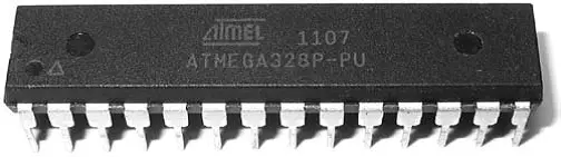
The Atmel 8-bit AVR RISC –based microcontroller combines 32 kB ISP flash memory with read-while-write capabilities, 1 kB EEPROM , 2 kB SRAM, 23 general purpose I/O lines, 32 general purpose working registers , three flexible timer/counters with compare modes, internal and external interrupts, serial programmable USART , a byte-oriented 2-wire serial interface, SPI serial port, 6-channel 10- bit A/D converter (8-channels in TQFP and QFN /MLF packages), programmable watchdog timer with internal oscillator , and five software selectable power saving modes. The device operates between 1.8-5.5 volts. The device achieves throughput approaching 1 MIPS per MHz.
16 MHz Crystal Oscillator

More commonly known as a crystal, the crystal oscillator creates an electrical signal with a very accurate frequency. In this case, the frequency is 16 MHz Crystals are not polarized. The schematic symbol is shown in Figure 3.11. The crystal determines the microcontroller’s speed of operation. For example, the microcontroller circuit we’ll be assembling runs at 16 MHz, which means it can execute 16 million processor instructions per second. That doesn’t mean it can execute a line of sketch or a function that rapidly, however, since it takes many processor instructions to interpret a single line of code.
Reset push button

This is a momentarily switching device that is used to ground the current flowing into the reset pin of the Microcontroller. The reset pin is kept high by a 10k resistor but when the push button is depressed the current flowing into this pin is grounded forcing the microcontroller to restart or reset.
RFID- RC522 Module

This is a simple but yet very effective radio frequency module that is used for scanning RFID cards. It uses electromagnetic fields to transfer data between cards and reader. And doesn’t need to be in the line of sight to work, placing the card on the designed area would do the trick. Our module Serial Peripheral Interface (SPI) protocol, making it to have a separate clock and data lines along which we can select our microcontroller we wish to talk to.
The interface of the Microcontroller to the RFID-RC522 Module is thus:
- Pin 10 of the Microcontroller is connected to the SDA Pin of RFID-RC522.
- Pin 13 of the Microcontroller is connected to the SCK Pin of RFID-RC522.
- Pin 11 of the Microcontroller is connected to the MOSI Pin of RFID-RC522.
- Pin 12 of the Microcontroller is connected to the MISO Pin of RFID-RC522.
- Pin NC of the Microcontroller is connected to the IRQ Pin of RFID-RC522.
- GND Pin of the Microcontroller is connected to the GND Pin of RFID-RC522.
- Pin 9 of the Microcontroller is connected to the RST Pin of RFID-RC522.
- 3.3V Pin of the Microcontroller is connected to the 3.3V Pin of RFID-RC522.
THE RELAY MODULE UNIT

This consist of a LOW Level 5V 4-channel relay interface board, and each channel needs a 15-20mA driver current. It can be used to control various appliances and equipment with large current. It is equipped with high-current relays that work under AC250V 10A or DC30V 10A. It has a standard interface that can be controlled directly by microcontroller. This module is optically isolated from high voltage side for safety requirement and also prevent ground loop when interface to microcontroller.
- Relay Maximum output: DC 30V/10A, AC 250V/10A.
- • 4 Channel Relay Module with Opto-coupler. LOW Level Trigger expansion board, which is compatible with Arduino control board.
- • Standard interface that can be controlled directly by microcontroller (8051, AVR, *PIC, DSP, ARM, ARM, MSP430, TTL logic).
- • Relay of high quality low noise relays SPDT. A common terminal, a normally open, one normally closed terminal.
- • Opto-Coupler isolation, for high voltage safety and prevent ground loop with microcontroller.
LCD Connector Wires and header socket pins:

This is a 16 in-line wires configured according to the number of the LCD inputs and output pins.
It reads and writes data communication from and to the MCU. In handling the LCD connector wires, care must be taken to ensure that each of the connector is matched according to its assigned pin hole.
The header socket pins is a male-female wire socket to the LCD connector wire. It makes it very simple to connect to the LCD and the MCU
Techniques
Thinning
Thinning involves the smooth scrapping of terminal components either by knife or sand paper before soldering.
Assembling of Components
The number of components determined the size of the VERO board used and in dimensioning the size of board, allowance is given for the arrangement if the need arises.
- Begin by placing the components that require a specific location first.
- Leave at least 10 centimeters between components and the VERO Board edge.
- Attempt to space out your components evenly horizontally and vertically and orient the circuit components the same direction whenever possible for consistency.
- Insure that the orientation of polarized parts is the same.
- Avoid placing your components at angles other than 0 or 90 degrees
- When it is necessary to have components on both sides, keep sensitive, heavy, or through hole components on the primary side. Also, any components that need special attention should be kept on the primary side of the printed circuit board as well.
- When deciding where to place components, trace lengths were minimized
Casing
In the selection of a suitable casing for the RFID controlled home appliances system, the components on the board will be taken into consideration; vents will be created around the cover. For cooling of the device and holes for the transformer and the voltage regulators.
Having completed mounting, soldering and interfacing all the components, this is followed by checking and confirming that the system is performing as per specification. It is necessary to carry out the short circuit, open circuit, load and no- load tests to confirm the integrity of the MCU, and RFID control unit. Before carrying out these tests we made sure that all connections to a power source are isolated.
To determine the effectiveness of the project, How to Build an RFID Automated Home Control System; two major tests namely Load and No-load tests were carried out (by connecting a LED to the output of the Microcontroller unit (MCU)).
These steps are very necessary for the project: How to Build an RFID Automated Home Control System
The Source-code
Since each tag and card has a unique ID, it is very important to know their identities and map their IDs to a specific set of functions. To do this on the Arduino platform, go to the Arduino IDE, open it and install the following MFRC RFID library.
After successful installation, open the IDE and click on File, scroll down to Examples and select MFRC and under the available options, open the ReadNUID and you will see something like this:
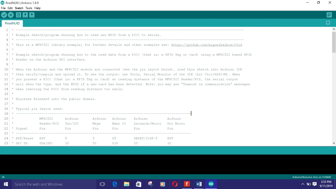
Verify your connection and click on verify on the IDE and after verification, upload the sketch. Open the Serial monitor, ensure that your baud rate is at 9600 and bring your tag closer to the MFRC reader to see each ID as shown on the Serial monitor. Copy the content.substring shown on the screen. Keep this safe and use it in the sketch below. By replacing ours with your very own content.substring ID codes.
To control only one socket switch and one AC light bulb; the following source code is used.
/*  Program  to use RFID CARDS TO CONTROL
 *   TWO HOME APPLIANCES
 */

//include the LCD lib
#include <LiquidCrystal.h>

 //include the RFID libs
#include <SPI.h>
#include <MFRC522.h>

 //declear the reset and SDA pins of RFID
#define SS_PIN 10
#define RST_PIN 9
MFRC522 mfrc522(SS_PIN, RST_PIN);   // Create MFRC522 instance.
//state the output pins for appliaces
#define LED1 A1
#define LED2 A2
int ledState1 = 0;
int ledState2 = 0;
LiquidCrystal lcd(7, 6, 5, 4, 3, 2);

void setup()
{
   // Initiate a serial communication
  Serial.begin(9600);
  // Initiate  SPI bus
  SPI.begin();
  // Initiate MFRC522
  mfrc522.PCD_Init();
  //begin the LCD
  lcd.begin(16, 2);
  Serial.println("Approximate your card to the reader...");
  Serial.println();
  pinMode(LED1, OUTPUT);
  pinMode(LED2, OUTPUT);
//display a welcome note
  lcd.setCursor(0, 0);
  lcd.print("WELCOME DAVID");
  delay(2000);
  lcd.setCursor(0, 0);
  lcd.print("RFID CONTROLLED ");
  lcd.setCursor(0, 1);
  lcd.print("HOME APPLIANCES");
  delay(3500);
  lcd.clear();

}
void ledOne()
{
   // Look for new cards
  if ( ! mfrc522.PICC_IsNewCardPresent())
  {
    return;
  }
  // Select one of the cards
  if ( ! mfrc522.PICC_ReadCardSerial())
  {
    return;
  }
  //Show UID on serial monitor
  Serial.print("UID tag :");
  String content= "";
  byte letter;
  for (byte i = 0; i < mfrc522.uid.size; i++)
  {
     Serial.print(mfrc522.uid.uidByte[i] < 0x10 ? " 0" : " ");
     Serial.print(mfrc522.uid.uidByte[i], HEX);
     content.concat(String(mfrc522.uid.uidByte[i] < 0x10 ? " 0" : " "));
     content.concat(String(mfrc522.uid.uidByte[i], HEX));
  }
  Serial.println();
  Serial.print("Message : ");
  content.toUpperCase();
  if (content.substring(1) == "0A DB D9 06") //change here the UID of the card/cards that you want to give access
  {
        // if the LED is off turn it on and vice-versa:
    if (ledState1 == 0) {
      ledState1 = 255;
      lcd.setCursor(2, 1);
      lcd.print("ON ");
    } else {
      ledState1 = 0;
      lcd.setCursor(2, 1);
      lcd.print("OFF ");
    }

    // set the LED with the ledState of the variable:
    analogWrite(LED1, ledState1);
  }
delay(500);
}
void ledTwo() {
   // Look for new cards
  if ( ! mfrc522.PICC_IsNewCardPresent())
  {
    return;
  }
  // Select one of the cards
  if ( ! mfrc522.PICC_ReadCardSerial())
  {
    return;
  }
  //Show UID on serial monitor
  Serial.print("UID tag :");
  String content= "";
  byte letter;
  for (byte i = 0; i < mfrc522.uid.size; i++)
  {
     Serial.print(mfrc522.uid.uidByte[i] < 0x10 ? " 0" : " ");
     Serial.print(mfrc522.uid.uidByte[i], HEX);
     content.concat(String(mfrc522.uid.uidByte[i] < 0x10 ? " 0" : " "));
     content.concat(String(mfrc522.uid.uidByte[i], HEX));
  }
  Serial.println();
  Serial.print("Message : ");
  content.toUpperCase();
  if (content.substring(1) == "35 F7 F0 D1") //change here the UID of the card/cards that you want to give access
  {
       // if the LED is off turn it on and vice-versa:
    if (ledState2 == 0) {
      ledState2 = 255;
      lcd.setCursor(12, 1);
      lcd.print("ON ");
    } else {
      ledState2 = 0;
      lcd.setCursor(12, 1);
      lcd.print("OFF ");
    }

    // set the LED with the ledState of the variable:
    analogWrite(LED2, ledState2);
  }
   delay(500);
}

void loop()
{
  lcd.setCursor(0, 0);
lcd.print("Light:   Socket:");
ledOne();
ledTwo();
}
Explantion of Code
Although the sketch contains comment lines to explain some of the sketch… But from the beginning line of code; we imported libraries for the Serial peripheral interface SPI, which is necessary since it is the type of communication the RFID RC522 uses. Then the lib for the LCD and the MFRC522 lib were also imported at line 6 through line 10.
At line 13 and 14, we define where connected out Slave Select pin and our Reset pin(which is pin 10 and 9 respectively). After creating the RC522 instance, we declare which of the MCU pins we are connecting the AC light bulb and the socket (line 17 and 18).
Since we are using an Active LOW relay module unit, We declared and put the relay state to be ON, at line 19 and 20. Next we declared where we are connecting the LCD data signal pins. Since we are using 4-bits, not 8-bits. We state it there.
In the void setup function, we kick started the SPI protocol and initialized the type of RFID at line 29 and 30 respectively. The same with the LCD at line 32 as we make our two outputs known.
After this, we print a welcome message, Since this project was inspired by Mr. David from Landmark varsity; we display his name. We would want the message displayed to stay for a while before disappearing; hence, we put a delay of 3.5 seconds. And we cleared the LCD to received more instructions from the MCU after that.
We created two functions: ledOne() and ledTwo() (at line 49 and 93 respectively) to handle the states of the AC light bulb and the Socket load point. Basically what these functions does is to check if there is the presence of the ring or tag that has been mapped to them and if there is; it would change the state on the MCU pins stated earlier from 0 to 255 and if it notice the tag or ring presence again it would change to the previous state and vice versa. This will create a kind of changeState effect any time it senses the RFID tag or card mapped to it.
The youtube video below shows How to Build an RFID Automated Home Control System. Click below to watch the video.
If you want to leanHow to Build an RFID Automated Home Control System that would control two AC light bulbs and two sockets switches, we use the following circuit diagram:

The Final Sketch below was used
/*  Program  to use RFID CARDS TO CONTROL
 *   FOUR HOME APPLIANCES
 */

//include the RFID libs
#include <SPI.h>
#include <MFRC522.h>

//include the LCD lib
#include <LiquidCrystal.h>

 //declear the reset and SDA pins of RFID
#define SS_PIN 10
#define RST_PIN 9
// Create MFRC522 instance.
MFRC522 mfrc522(SS_PIN, RST_PIN);   // Create MFRC522 instance.
//declear what LCD pins u are sending data
LiquidCrystal lcd(8, 7, 6, 4, 3, 2);

#define BULB1 A1
#define BULB2 A2
#define SOCKET1 A3
#define SOCKET2 A4
int bulbState1 = 0;
int bulbState2 = 0;
int socketState1 = 0;
int socketState2 = 0;

void setup() {
 pinMode(BULB1, OUTPUT);
 pinMode(BULB2, OUTPUT);
 pinMode(SOCKET1, OUTPUT);
 pinMode(SOCKET2, OUTPUT);
 //turn all the relays off
 digitalWrite(BULB1, 255);
 digitalWrite(BULB2, 255);
 digitalWrite(SOCKET1, 255);
 digitalWrite(SOCKET2, 255);
   // Initiate a serial communication
  Serial.begin(9600);
  // Initiate  SPI bus
  SPI.begin();
  // Initiate MFRC522
  mfrc522.PCD_Init();
  //begin the LCD
  lcd.begin(16, 2);
//display a welcome note
  lcd.setCursor(0, 0);
  lcd.print("WELCOME UCHE");
  delay(2000);
  lcd.setCursor(0, 0);
  lcd.print("RFID CONTROLLED ");
  lcd.setCursor(0, 1);
  lcd.print("HOME APPLIANCES");
  delay(3500);
  lcd.clear();
}

  void bulbOne() {
     // Look for new cards
  if ( ! mfrc522.PICC_IsNewCardPresent())
  {
    return;
  }
  // Select one of the cards
  if ( ! mfrc522.PICC_ReadCardSerial())
  {
    return;
  }
  //Show UID on serial monitor
  Serial.print("UID tag :");
  String content= "";
  byte letter;
  for (byte i = 0; i < mfrc522.uid.size; i++)
  {
     Serial.print(mfrc522.uid.uidByte[i] < 0x10 ? " 0" : " ");
     Serial.print(mfrc522.uid.uidByte[i], HEX);
     content.concat(String(mfrc522.uid.uidByte[i] < 0x10 ? " 0" : " "));
     content.concat(String(mfrc522.uid.uidByte[i], HEX));
  }
  Serial.println();
  Serial.print("Message : ");
  content.toUpperCase();
  //this is where u put the UID of the card that you want to give access
  if (content.substring(1) == "55 E5 07 88")
 // previousMillis = currentMillis;
  { if (bulbState1 == 0) {
      bulbState1 = 255;
      lcd.setCursor(0, 1);
      lcd.print("OFF ");
      }
   else {
      bulbState1 = 0;
      lcd.setCursor(0, 1);
      lcd.print("ON ");
      }
    // set the bulb with the bulbState of the variable:
    analogWrite(BULB1, bulbState1);
  }
  delay(150);
}

void bulbTwo() {
     // Look for new cards
  if ( ! mfrc522.PICC_IsNewCardPresent())
  {
    return;
  }
  // Select one of the cards
  if ( ! mfrc522.PICC_ReadCardSerial())
  {
    return;
  }
  //Show UID on serial monitor
  Serial.print("UID tag :");
  String content= "";
  byte letter;
  for (byte i = 0; i < mfrc522.uid.size; i++)
  {
     Serial.print(mfrc522.uid.uidByte[i] < 0x10 ? " 0" : " ");
     Serial.print(mfrc522.uid.uidByte[i], HEX);
     content.concat(String(mfrc522.uid.uidByte[i] < 0x10 ? " 0" : " "));
     content.concat(String(mfrc522.uid.uidByte[i], HEX));
  }
  Serial.println();
  Serial.print("Message : ");
  content.toUpperCase();
  if (content.substring(1) == "22 80 F5 BA")
   {
    if (bulbState2 == 0) {
      bulbState2 = 255;
      lcd.setCursor(4, 1);
      lcd.print("OFF ");
      }
  else {
      bulbState2 = 0;
      lcd.setCursor(4, 1);
      lcd.print("ON ");
     }
    analogWrite(BULB2, bulbState2);
  }
   delay(150);
}

void socketOne() {
     // Look for new cards
  if ( ! mfrc522.PICC_IsNewCardPresent())
  {
    return;
  }
  // Select one of the cards
  if ( ! mfrc522.PICC_ReadCardSerial())
  {
    return;
  }
  //Show UID on serial monitor
  Serial.print("UID tag :");
  String content= "";
  byte letter;
  for (byte i = 0; i < mfrc522.uid.size; i++)
  {
     Serial.print(mfrc522.uid.uidByte[i] < 0x10 ? " 0" : " ");
     Serial.print(mfrc522.uid.uidByte[i], HEX);
     content.concat(String(mfrc522.uid.uidByte[i] < 0x10 ? " 0" : " "));
     content.concat(String(mfrc522.uid.uidByte[i], HEX));
  }
  Serial.println();
  Serial.print("Message : ");
  content.toUpperCase();
  if (content.substring(1) == "F3 0A 50 2D")
  {
    if (socketState1 == 0) {
      socketState1 = 255;
      lcd.setCursor(9, 1);
      lcd.print("OFF ");
      }
    else {
      socketState1 = 0;
      lcd.setCursor(9, 1);
      lcd.print("ON ");
      }
    analogWrite(SOCKET1, socketState1);
  }
   delay(150);
}

void socketTwo() {
   // Look for new cards
  if ( ! mfrc522.PICC_IsNewCardPresent())
  {
    return;
  }
  // Select one of the cards
  if ( ! mfrc522.PICC_ReadCardSerial())
  {
    return;
  }
  //Show UID on serial monitor
  Serial.print("UID tag :");
  String content= "";
  byte letter;
  for (byte i = 0; i < mfrc522.uid.size; i++)
  {
     Serial.print(mfrc522.uid.uidByte[i] < 0x10 ? " 0" : " ");
     Serial.print(mfrc522.uid.uidByte[i], HEX);
     content.concat(String(mfrc522.uid.uidByte[i] < 0x10 ? " 0" : " "));
     content.concat(String(mfrc522.uid.uidByte[i], HEX));
  }
  Serial.println();
  Serial.print("Message : ");
  content.toUpperCase();
  if (content.substring(1) == "8B 33 E9 A9")
  {
    if (socketState2 == 0) {
      socketState2 = 255;
      lcd.setCursor(13, 1);
      lcd.print("OFF ");
      }
  else {
      socketState2 = 0;
      lcd.setCursor(13, 1);
      lcd.print("ON ");
      }
  analogWrite(SOCKET2, socketState2);
  }
   delay(150);
}

void loop() {
  lcd.setCursor(0, 0);
  lcd.print("L1: L2:  S1: S2:");
  bulbOne();
  bulbTwo();
  socketOne();
  socketTwo();
Conclusion
We hope this helps and now you know how to build an RFID automated home control system. What do you think? Can you build similar a project design? Let us know in the comment section if you followed this guide to achieve a successful project. You can contact us and send us pictures and videos of your project design on WhatsApp, Twitter, Telegram, Instagram to and send us pictures or ask questions too.
Read More
- HOW TO GENERATE ELECTRICITY WITH FOOTSTEPS
- SOLAR POWERED IRRIGATION SYSTEM PROJECT
- ESP32 CAMERA FOR HOME AUTOMATION
- REMOVE JAPANESE HACK VIRUS FROM YOUR WEBSITE
Feel free to leave us a comment at any time. Thanks.
Frequently Asked Questions
- What type of RFID tags should I use for my home automation system?
- The choice of RFID tags depends on your specific requirements, such as read range, durability, and security. Common types of RFID tags include passive tags, active tags, and near-field communication (NFC) tags.
- How can I integrate RFID into my existing home automation system?
- You can integrate RFID into your existing home automation system by using RFID readers and controllers that are compatible with your system’s protocol.
- Can RFID technology be used for home security?
- Yes, RFID technology can be used for home security applications, such as access control, intrusion detection, and perimeter security.
- Are RFID tags expensive?
- The cost of RFID tags varies depending on the type of tag, read range, and quantity. However, RFID technology has become more affordable in recent years.
- What are the potential challenges of using RFID technology in home automation?
- Some potential challenges include interference from other electronic devices, battery life issues for active tags, and the need for proper installation and configuration.


