The metal detector DIY project with SMS is a project design that incorporates a metal detector sensor to detect metallic objects in close proximity. It comes with an SMS-enabled notification upgrade that would instantly send out an SMS to a predefined personnel’s phone number once a metal or electronic device(s) was detected. The design has features like its portable size and runs on rechargeable batteries. In designing this project, we had to calculate the feasibility of the needed materials’ cost in order to make sure that we were undertaking an exorbitant project. This SMS based metal detector project is about metal detector design with SMS notification. Below is a description of the components used for the implementation of the metal detector with SMS alert system design.
MATERIALS
- 3.7V 1800mAh Li-ion Rechargeable Battery
- 3.7V 1800mAh Casing
- 3.7 Lipo 1A Battery Charging Board Charger Module Mini USB Interface
- LM323T Voltage Regulator
- The 1k resistor
- 330-ohm resistor
- LED
- 1N4148 diode
- Perforated board (stripped line type)
- Connecting jumper wire
- 10nF capacitor
- GSM Module (SIM900L)
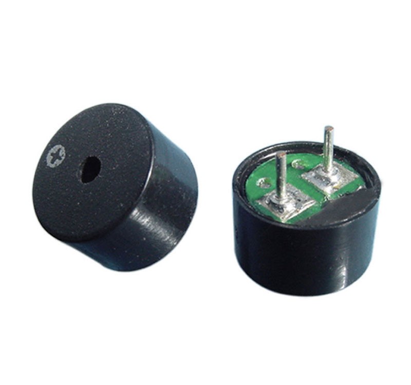
- 5V Passive Buzzer
3.7V 1800mAh Li-ion Rechargeable Battery:
The power unit for the design depended mainly on DC supply from rechargeable batteries, each rated 3.7V 1800mAh. And three pieces of 3.7V 1800mAh Li-ion batteries gave us the needed voltage for the GSM module. Also, these were rechargeable batteries, so we used a Lipo battery charging board.
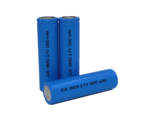
The 3.7-volt rechargeable battery can output a current of 1.8 A in one hour. It is durable and can be charged very fast. It is also portable, and as such, was ideal for using as a power source for the project design.
3.7V 1800mAh Casing:
The above pictured batteries needed a casing so we used One 3.6V-3.7V Battery Charging Discharging Control Holder Case Li-ion w/1S3P PCM.
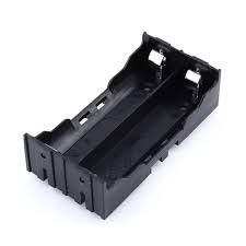
This is a plastic DIY Lithium battery box battery holder with pin suitable for 2×18650 (3.7V-7.4V) Lipo battery. The casing is of high quality and can withstand temperatures of about 95°C. It maintains firm hold with the batteries inside it and offers safety from short circuiting and wire burn out. A total of 3 battery were connected in series to give us a 12V approximately 5A output for the GSM module.
3.7 Lipo 1A Battery Charging Board Charger Module Mini USB Interface
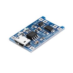
The Lipo charging board module uses the mature charging chip TP4056, simple peripheral circuits that has a good protection performance and high charging accuracy. It comes with full machinery automated processing and has high reliability. Its output charging current can be adjusted by just changing the circuit board fixed resistor values, this would in turn change the output current to the 100mA-1000mA. The input reverse connection has no effect on the chip, but the output (battery end) reverse connection will burn out the chip. When measuring with an Ampere meter, it is best in series connected to the 5V input end. The charging current is best to be 0.37 times of the battery capacity,
It is very convenient for portability and size conservation. Below is a summary of its datasheet.
Datasheet Specificatiuon:
- Item Name: Lipo battery charging board
- Item NO. : TP4056
- Charging Method: linear charge
- Charging Current: 1A Adjustable
- Charge Accuracy: 1.5 pct
- Input Voltage: 4.5V – 5.5V
- Full Charge Voltage: 4.2V
- Charging Indicator: Blue light lit charge,red light lit full charge
- Charging Input Interface: Mini USB
- Working Temperature: -10 Degree to +85 Degree
- Reverse: NO
- Usage: Used for single lipo or multi-section lipo parallel charging, can take power from the USB port.
- Current Regulation: Can auto regulate current charging.
LM323T Voltage Regulator
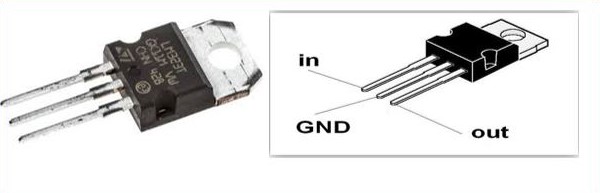
The voltage regulator IC, L232T is used to provide a regulated 5V DC output. Input voltage fed into the input pin (pin 1) was 2 volts more than the rated output voltage (in our own case 12V) for proper working of Integrated Circuit (IC). For better results, a filter ripple capacitor of 1uF was connected to the output of the IC L323T to eliminate the noise, produced by transient changes in voltage.
Datasheet Specifications:
- Output Voltage: +5V, up to 3A with peak current of 4.5A
- Current Output: up to 3.5A
- Input Voltage: 7V Minimum, 35V Maximum
- Package : TO-220
- Pin Spacing Pitch : 2.54mm (0.1in)
- Hole Diameter : 3.8mm (0.15in)
- STMicroelectronics Part Number: L323T
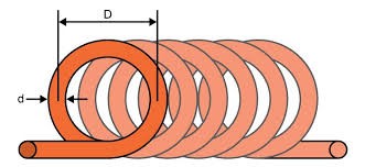
Metal Detector Unit
This unit is mainly composed of the resistor, the inductor, and the capacitor used for the EMF pulsating device. In our design of a resistor-inductor-capacitive (RLC) circuit, we made use of a hand-made 150 coil turns of size wire gauge 30 wound about a diameter of 6cm to form the EMF emitting part of our design.
The Metal Detector DIY Project with SMS depends on us building an LC high pass filter with the help of a coil and a capacitor. According to the equation of Mutual inductance;

Where,
L is Inductance in Henry
μo is permeability, its 4π*10-7 for Air
N is number of turns of wire coil
A is inner Core Area (πr2) in m2
L is length of the Coil in meters
Whenever a current passes through a coil, it generates a magnetic field around it. And the change in the magnetic field generates an electric field. Now according to Faraday’s law, because of this Electric field, a voltage develops across the coil which opposes the change in magnetic field and that’s how our coil develops the Inductance, means the generated voltage opposes the increase in the current.
When we place a metal near the coil then coil changes its inductance. This change in inductance depends upon the metal type. And for a ferromagnetic material like iron it increases. Although, it decreases for non-magnetic materials.
The medium of flow of magnetic field generated by the inductor is nothing or air. Depending on the core of the coil, the inductance value changes drastically.
The coil wound here is an air cored one, so when we bring a metal piece near the coil, the metal piece acts as a core for the air cored inductor. Hence, the inductance of the coil changes or increases considerably. With this sudden increase in inductance of coil the overall reactance or impedance of the LC circuit changes by a considerable amount when compared without the metal piece.
5cm diameter Coil:
10nF 100VDC Polyester Capacitor:
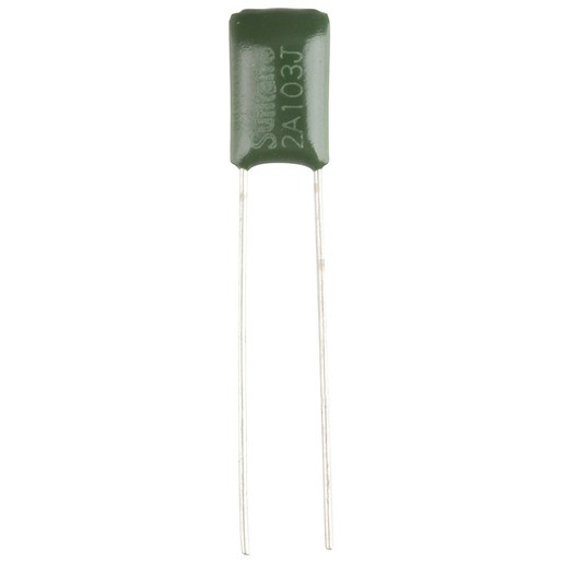
10nF polyester capacitor used in the design
Polyester capacitors offer good stability, a large range of values at low cost, and it is used for charging and discharging the inductor in the circuit.
330Ω RESISTOR
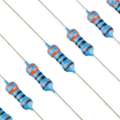
Specifications:
- Resistance: 330 Ohms
- Wattage Rating: 0.25 Watt
- Tolerance: 1%
- Metal Film
- Lead Free
- ROHS compliant
- Diameter of Leads: 0.43mm (0.02in)
- Length of Leads: ~28mm (1.1in)
IN4148 DIODE:
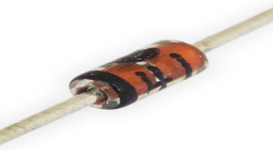
The 1N4148 is a standard silicon switching signal diode. This diode, 1N4148 can switch within applications of up to about 100 MHz with a reverse-recovery time of no more than 4 ns. It was fabricated in planar technology, and encapsulated in a hermetically sealed leaded glass DO-35 package.
SIM900L GSM module:
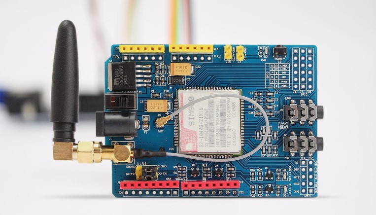
SIM900L GSM/GPRS shield is a GSM modem. It allows what a normal cell phone can do: Make or receive phone calls, connecting to internet through GPRS, TCP/IP, and more. It supports quad-band GSM/GPRS network, meaning it works pretty much anywhere in the world. The shield itself was designed to surround the SIM900L chip.
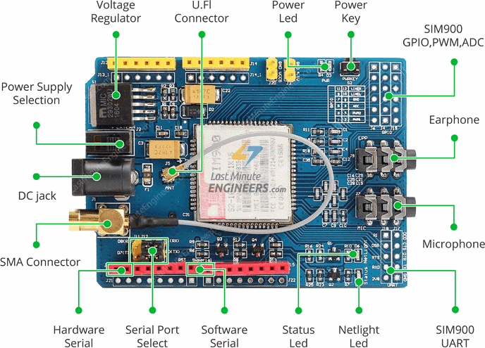
pin diagram of SIM900L from lastminuteengineers
SIM900L Shield LED Status Indicators
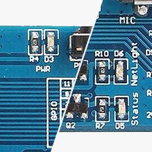
The LEDs blinking statuses on the SIM900L board has different interpretation. The LEDs on the board is two, namely:
PWR: This LED is connected to the shield’s power supply line. If this LED is on, the shield is receiving power.
Status: This LED indicates SIM900’s working status. If this LED is on, the chip is in working mode.
Netlight: This LED indicates the status of our cellular network. It blinks at various rates to show what state it’s in.
- off: The SIM900 chip is not running
- 64ms on, 800ms off: The SIM900L chip is running but not registered to the cellular network yet.
- 64ms on, 3 seconds off: The SIM900 chip is registered to the cellular network & can send/receive voice and SMS.
- 64ms on, 300ms off: The GPRS data connection we requested is active.
Powering the SIM900L
Depending on which state it’s in, the SIM900 can be a relatively power-hungry device. The maximum current draw of the chip is around 2A during transmission burst. It usually won’t pull that much, but may require around 216mA during phone calls or 80mA during network transmissions.
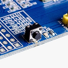
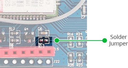
To use the SIM900L, we hard to turn on the chip. To do this we had to press and hold (for a few seconds) the ON button by the side as shown in the figure above. But we needed to turn on the GSM module every time we power on the design. To do this we had to use the software trigger version of turn on the GSM module. We first connected the D9 of the SIM900L to D9 of the MCU. Next we soldered the SMD jumper as shown in the figure below:
Interfacing GSM Module Sim900L with MCU
Using the UART Communication:
The SIM900 GSM/GPRS shield uses universal asynchronous receiver-transmitter (UART) protocol to communicate with the MCU. The chip supports baud rate from 1200bps to 115200bps with Auto-Baud detection.
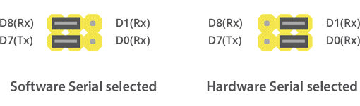
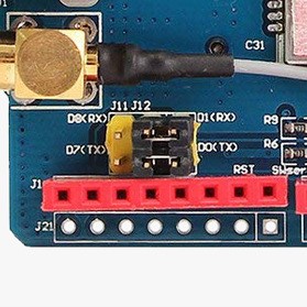
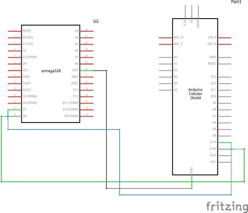
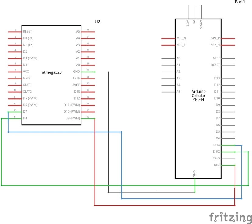
After ensuring that the jumper cap is placed on the software serial port select, we connected the MCU according to the circuit diagram shown in figure below.
Although the GSM module could also work on 5V DC but we connected the sim900L to an external power of source of not less than 7V 2A supply. The module adjustable voltage regulator makes it possible for it to handle the voltage at this level.
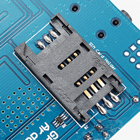
We used a 2G full sized SIM card and inserted it at the back of the module in its SIM socket. We were careful enough to unlock the latch, push the top part of the assembly, and then lift it up. We Placed the SIM card into the bottom part of the socket. Then fold the arm back into the body of the socket, and gently push it forward towards the LOCK position.
Hence, the new circuit diagram would be thus:
5V Passive Buzzer
Generating Pulse from the Microcontroller
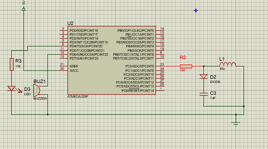
We send a pulse from our microcontroller for Metal Detector DIY Project with SMS to the RL high pass filter, as such, short spikes will be generated by the coil in every transition. The pulse length of the generated spikes is proportional to the inductance of the coil. So with the help of these spike pulses we can measure the inductance of Coil. But here it is difficult to measure inductance precisely with that spikes because that spikes are of very short duration. We used a capacitor to solve this problem which is charged by the rising pulse or spike. And it required few pulses to charge the capacitor to the point where its voltage can be read by analog pin ADC0. And the microcontroller reads the voltage of this capacitor by using ADC syntax. After reading voltage, capacitor quickly discharged since we made it an output and setting it to LOW. This whole process takes around 200 microseconds to complete. For better result, we repeat measurement and took an average of the results. That’s how we can measure the approximate inductance of Coil. After getting the result we transfer the results to the LED and buzzer to detect the presence of metal.
Program for Testing Software Trigger
In our program to be uploaded into the MCU, we created a function where we can turn on the sim900L using software trigger. The syntax for the program was:
Testing Attention (AT) Commands:
For sending AT commands void SIM900power()
{
  pinMode(9, OUTPUT);
  digitalWrite(9,LOW);
  delay(1000);
  digitalWrite(9,HIGH)
Testing Attention (AT) Commands:
For sending AT commands and communicating with the SIM900 shield, we will use the serial monitor. Below codes are the the syntax that will enable the MCU to communicate with the SIM900 shield on serial monitor window.
//since we were using the software serial, we added the library
#include <SoftwareSerial.h>

//Create software serial object to communicate with SIM900
//SIM900 Tx & Rx is connected to MCU #7 & #8
SoftwareSerial mySerial(7, 8);

void setup()
{
  //Begin serial communication
  Serial.begin(9600);

  //Begin serial communication with MCU and SIM900
  mySerial.begin(9600);

  Serial.println("Initializing...");
  delay(1000);

//Handshaking with SIM900
  mySerial.println("AT");
updateSerial();
//Signal quality test, value range is 0-31 , 31 is the best
  mySerial.println("AT+CSQ");
  updateSerial();
//Read SIM information to confirm whether the SIM is plugged
  mySerial.println("AT+CCID");
  updateSerial();
//Check whether it has registered in the network
  mySerial.println("AT+CREG?");
  updateSerial();
}


void loop()
{
  updateSerial();
}


void updateSerial()
{
  delay(500);
  while (Serial.available())
  {
//Forward what Serial received to Software Serial Port
    mySerial.write(Serial.read());
  }
  while(mySerial.available())
  {
//Forward what Software Serial received to Serial Port
    Serial.write(mySerial.read());
  }
}
Code explanation:
AT – It is the most basic AT command. It initializes Auto-baud’er. When this command worked, we saw its characters echo, telling us that it understood us correctly. This paved way for us to use some other commands to query the GSM module and get information like:
AT+CSQ – meaning check signal strength query; it checks the ‘signal strength’ – the first number is dB strength, it should be higher than around 5. For us, being higher is better. This our length and type of antenna and location played a very vital role in that.
AT+CCID – this command gets the SIM card number – it tests that the SIM card is found OK and using it we verified the number written on the card.
AT+CREG? This command checks if the SIM is on a registered network Check that you’re registered on the network. The second number should be 1 or 5. If 1, it showed that our SIM was on a registered home network and 5 indicates roaming network. Any other number than these two numbers showed our SIM was not registered to any network.
Internally Charging the LiPo Batteries:
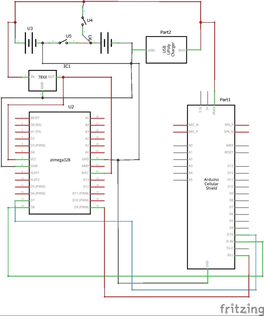
The Power Supply for the design consist of two LiPo 4.2V 3800mAH batteries connected in series. In order to recharge these batteries we had to use a single 4.2 1A charger and connected the outputs in parallel the batteries terminals. But the series connection posed a problem so we had to add two switches that would open the series connection when it is time for charging and close it when we are not charging the batteries as shown above.
The microcontroller uses 5V DC supply and the 8.4V formed by the series connection of the two batteries would only fry it. So we used a step-down converter of a 78xx series family viz; LM323T. It regulated the input voltage to a steady 5V output at 2A current for the Vcc of the MCU.
#include <SoftwareSerial.h>

SoftwareSerial mySerial(7, 8);

int Seven = 10;
#define capPin A1
#define buz 11
#define pulsePin A0
#define led 12
#define ledRead 6
#define led2 5

long sumExpect=0; //running sum of 64 sums
long ignor=0; //number of ignored sums
long diff=0; //difference between sum and avgsum
long pTime=0;
long buzPeriod=0;


void setup()
{
  mySerial.begin(9600);   // Setting the baud rate of GSM Module
  Serial.begin(9600);    // Setting the baud rate of Serial Monitor (Arduino)
  pinMode(Seven, INPUT);
  delay(100);
pinMode(pulsePin, OUTPUT);
digitalWrite(pulsePin, LOW);
pinMode(capPin, INPUT);
pinMode(buz, OUTPUT);
pinMode(ledRead, INPUT);
pinMode(led2, OUTPUT);
digitalWrite(buz, LOW);
pinMode(led, OUTPUT);

pinMode(9, OUTPUT);
//this turns on the sim900 automatcally
  digitalWrite(9,LOW);
  delay(1000);
  digitalWrite(9,HIGH);
  delay(2000);
  digitalWrite(9,LOW);
  //wait for 3sec
  delay(3000);
}

void SendMessage()
{
  mySerial.println("AT+CMGF=1");    //Sets the GSM Module in Text Mode
  delay(1000);  // Delay of 1000 milli seconds or 1 second
  mySerial.println("AT+CMGS="+2347062174135"r"); // Replace this with mobile number
  delay(1000);
  mySerial.println("A METAL HAS BEEN DETECTED,SEARCH VERY WELL ");// The SMS text we sent out
  delay(100);
   mySerial.println((char)26);// ASCII code of CTRL+Z
  delay(1000);
}


 void RecieveMessage()
{
  mySerial.println("AT+CNMI=2,2,0,0,0"); // AT Command to receive a live SMS
  delay(1000);
 }


void applyPulses()
{
for (int i=0;i<3;i++)
{
digitalWrite(pulsePin,HIGH); //take 3.5 uS
delayMicroseconds(3);
digitalWrite(pulsePin,LOW); //take 3.5 uS
delayMicroseconds(3);
}
}


void loop(){
int pinSeven = digitalRead(Seven);

if (Serial.available()>0)  {

    }

 if(pinSeven == HIGH){

  int minval=1023;
int maxval=0;
long unsigned int sum=0;

  for (int i=0; i<256; i++)
{
//reset the capacitor
pinMode(capPin,OUTPUT);
digitalWrite(capPin,LOW);
delayMicroseconds(20);
pinMode(capPin,INPUT);
applyPulses();
//read the charge of capacitor
int val = analogRead(capPin); //takes 13x8=104 microseconds
minval = min(val,minval);
maxval = max(val,maxval);
sum+=val;
long unsigned int cTime=millis();
char buzState=0;
if (cTime<pTime+10)
{
if (diff>0)
buzState=1;
else if(diff<0)
buzState=2;
}
if (cTime>pTime+buzPeriod)
{
if (diff>0)
buzState=1;
else if (diff<0)
buzState=2;
pTime=cTime;
}
if (buzPeriod>300)
buzState=0;
if (buzState==0)
{
digitalWrite(led, LOW);
noTone(buz);
}
else if (buzState==1)
{
tone(buz,2000);
digitalWrite(led, HIGH);

}
else if (buzState==2)
{
tone(buz,500);
digitalWrite(led, HIGH);

}

}
//subtract minimum and maximum value to remove spikes
sum-=minval;
sum-=maxval;
if (sumExpect==0)
sumExpect=sum<<6; //set sumExpect to expected value
long int avgsum=(sumExpect+32)>>6;
diff=sum-avgsum;
if (abs(diff)<avgsum>>10)
{
sumExpect=sumExpect+sum-avgsum;
ignor=0;
}
else
ignor++;
if (ignor>64)
{
sumExpect=sum<<6;
ignor=0;
}
if (diff==0)
buzPeriod=1000000;
else
buzPeriod=avgsum/(2*abs(diff));
}

if((digitalRead(ledRead) ==HIGH) && (pinSeven == HIGH)){
  SendMessage();

}


 else{

  }

  if (mySerial.available()>0)
   Serial.write(mySerial.read());

}
That is the final Arduino sketch for the Metal Detector DIY Project with SMS. And once uploaded, the Metal Detector DIY Project with SMS works according to specification.
Conclusion
Now you know how to design Metal Detector DIY Project with SMS from beginning to finish. Let us know in the comment section how your desing went. You can also send us videos and pictures of your project n any of the social media handles below.

