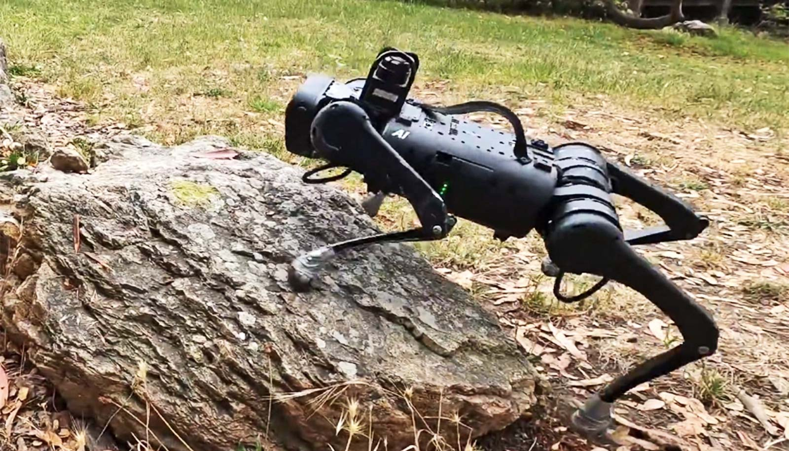
The UC San Diego-led team created an improved set of algorithms that allowed four-legged robots to navigate difficult terrain while avoiding stationary and moving obstacles while walking and running.
The four-legged robot overcoming tough terrains
These researchers have made significant progress towards constructing these four-legged robots, now, capable of conducting search and rescue missions or information gathering operations in hazardous or hard-to-reach environments for humans. The team showcased their work at the 2022 IROS Conference in Kyoto, Japan.
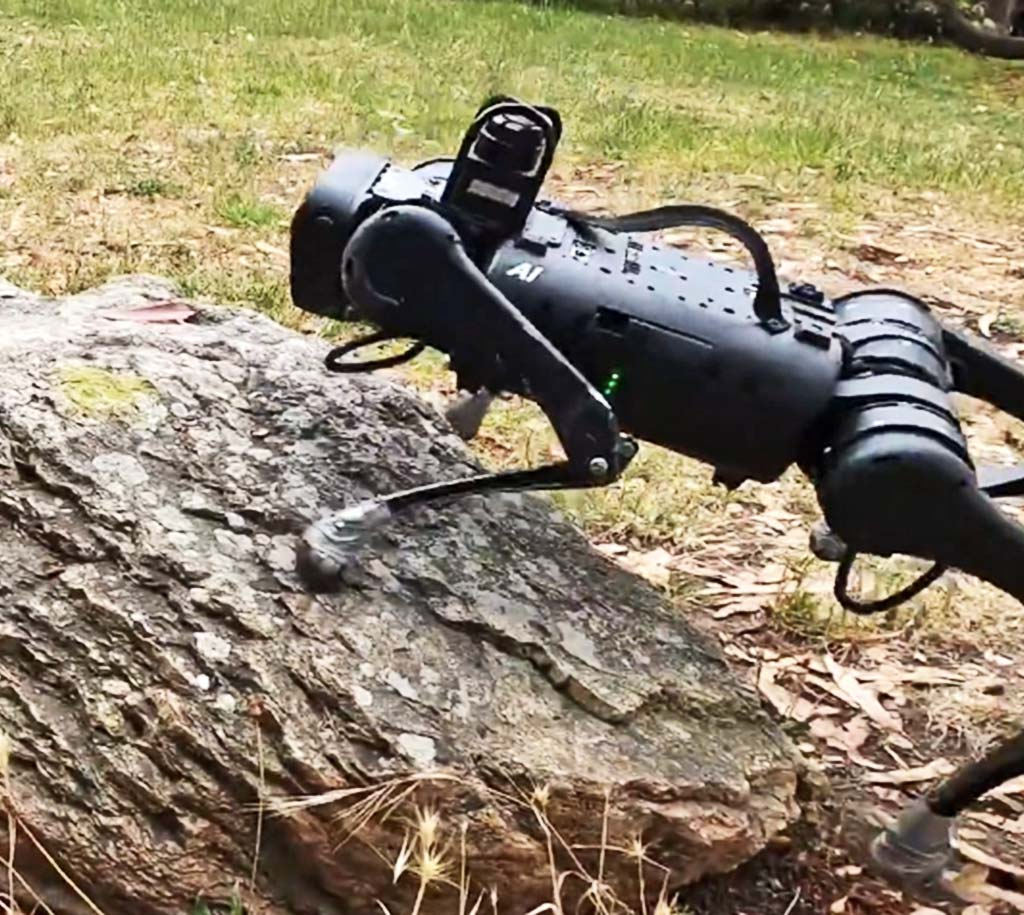
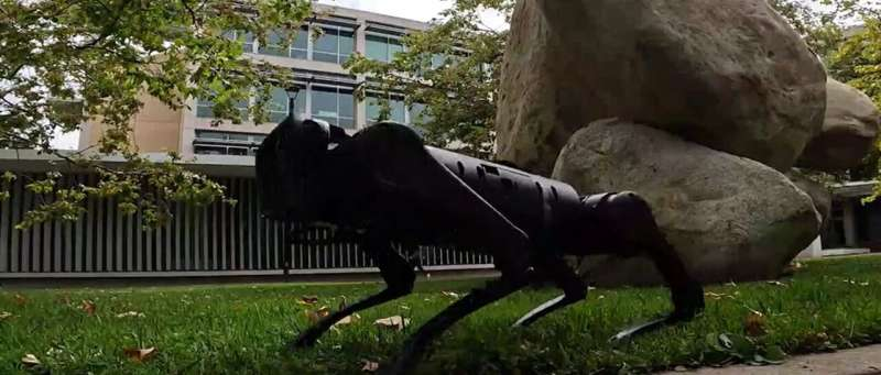
four-legged robots running in the wild
These engineers have created a set of algorithms allowing four-legged robots to traverse complex terrain while avoiding static and moving obstacles. Thereby bringing researchers closer to building robots for search and rescue or data collection in hazardous or inaccessible areas. The system enhances the versatility of the robots by combining visual and proprioceptive senses, the latter referring to the robot’s awareness of movement, direction, speed, location, and touch, specifically the sensation of the ground beneath its feet.
According to the senior author of the study, Xiaolong Wang, a professor of electrical and computer engineering at UC San Diego’s Jacobs School of Engineering, before this breakthrough, most training methods for legged robots to walk and move either use proprioception or vision, but not both simultaneously.
“In one case, it’s like training a blind robot to walk by just touching and feeling the ground. And in the other, the robot plans its leg movements based on sight alone. It is not learning two things at the same time,” said Wang. “In our work, we combine proprioception with computer vision to enable a legged robot to move around efficiently and smoothly—while avoiding obstacles—in a variety of challenging environments, not just well-defined ones.”
Wang and his team created a system that blends data from a depth camera on the robot’s head and sensors on its legs using specialized algorithms. This was challenging because in real-world scenarios, there is sometimes a slight delay in image transmission from the camera, causing the data from the two sensing modes to not always arrive simultaneously, as explained by Wang.
Conclusion
The four-legged robots are expected to make great strides in the coming years. The advantage it enjoys over human endeavors is too great to be ignored. And its ability to detect and process information faster without relying on feelings or emotions makes it an excellent tool to be used in the wild.
Developing Moral Self-Driving Vehicles; The “trolley problem,” a famous thought experiment, poses the question: Should you move a lever to reroute a runaway trolley so that it kills one person instead of five? What if, as an alternative, you had to push someone into the trolley’s tracks in order to stop it? What option is moral in each of these situations?
Philosophers have argued for decades about whether we should choose a utilitarian solution (what is best for society; in this case, fewer deaths) or a one that prioritizes individual rights (such as the right not to be purposefully placed in danger).
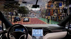
Designers of automatic vehicles have also thought about how AVs might handle similar problems in recent years when faced with unforeseen driving scenarios. What should the AV do, for instance, if a bicycle abruptly enters its lane? Should it hit the cyclist or swerve into oncoming traffic?
The answer is right in front of us, says Chris Gerdes, co-director of the Center for Automotive Research at Stanford (CARS) and professor emeritus of mechanical engineering. The social agreement we currently have with other drivers, as outlined in.
How might current traffic regulations influence automated vehicles’ moral behavior?
Always observe the law is the company policy of Ford. Does that policy apply to automated driving? is the simple question that gave rise to our research. And under what circumstances, if ever, is it moral for an AV to break the law?
As we investigated these issues, we found that, in addition to the traffic code, appellate rulings and jury instructions also contribute to the development of the social contract that has evolved over the more than a century that we have been operating automobiles. And at the heart of that social contract is the obligation to drive safely and with consideration for other road users, abiding by the law only when it’s absolutely necessary to do so. Basically: In the same circumstances where breaking the law seems appropriate
Using relatively no power, the device broadcasts radio waves while being compliant with physics.
At first glance, a novel ultralow-power communication technique appears to defy the laws of physics. By simply opening and closing a switch that links a resistor to an antenna, it is feasible to wirelessly send data. There is no need to supply the antenna with power. This is the new device that uses relatively no power to broadcast radio waves.
All kinds of data-transmitting devices, including tiny sensors and implanted medical devices, might be created using our methodology in combination with methods for obtaining energy from the environment without the use of batteries or other power sources. These include sensors for intelligent agriculture, implantable electronics that never need batteries, improved contactless credit cards, and perhaps even new satellite communication techniques.
No further energy is required to transfer the information outside the energy used to flick the switch. In this instance, the switch is a transistor, a switch that is electrically controlled, has no moving components, and uses a very small amount of electricity.
A switch links and disconnects a powerful electrical signal source—possibly an oscillator that emits radio waves—in the most basic version of conventional radio.
This blog post has shown that it is quite possible to have a device that uses relatively no power to broadcast radio waves. This is a great step because having no batteries or power source to work with is the way to solve some energy dependency and efficiency issues globally.
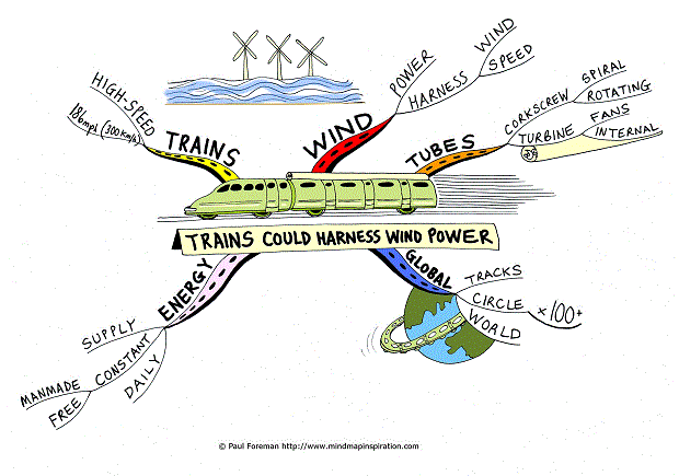
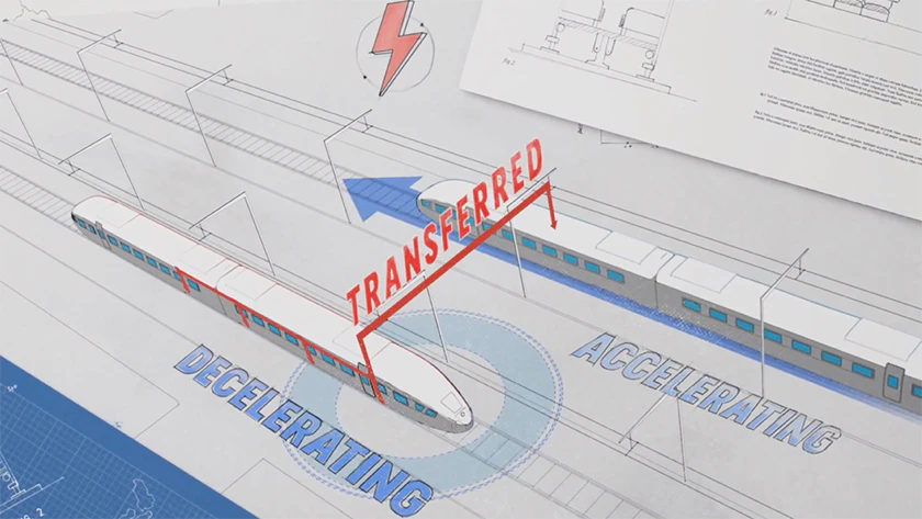
The Railway Technologies Laboratory and the Virginia Tech Center for Vehicle Systems and Safety (CVeSS) are working to capture the energy generated by moving trains and convert it into useful electricity.
Seventy-six percent of the miles of train tracks in America are located in remote places without the electricity needed to run smart rail systems. These sophisticated devices include track health monitoring, wireless communications, and technology for roadside safety. Mehdi Ahmadian, director of CVeSS, says it can be difficult to get energy to that gear. Power generators that use propane need maintenance and refueling, while solar panels are vulnerable to damage or theft.
Researchers at CVeSS set out to develop a more robust system that would power these gadgets, discourage theft, and require less upkeep.
Motion research
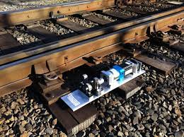
After several years of design review, CVeSS researchers created a new kind of tie that replaces the conventional wooden variety and is equipped to generate power. Their high-tech tie, placed underneath the rail, is topped with a heavy metal bar mounted on a spring. As the wheels of the train pass over the rail, the train’s weight pushes down on that bar, triggering a series of gears. Those gears rotate a generator, creating electricity, which can then be stored in a battery.
After developing this viable idea, the team next created a prototype. The researchers successfully tested the device in the lab, and Ahmadian started conversations about the technology with familiar industry partners. Norfolk-Southern agreed to host the deployment of the new rail on a section of its track this past August. Since that rollout, the CVeSS team has been collecting data to determine the amount of power that can be generated and the best ways to optimize the device’s design.
A rail with a function
Researchers were able to determine how much power the rail may generate and how that power might be used as trains went over it.
We are capturing 15 to 20 watts of power for each train wheel that passes, according to Ahmadian. “If we have a lengthy train, it would have 800 wheels and generate 1.6 kilowatts, with maybe 200 railcars. Once we have that energy stored, we may use it to incorporate sensors into the tracks to give them greater intelligence.
The use of their energy harvesting system could result in a bigger extension of the crucial sensor networks that maintain the safety of railways.
Not because we lack the technology, but rather because the capacity to monitor the track with that equipment is largely absent.
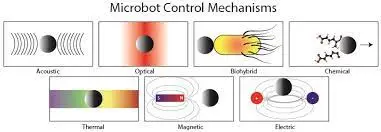
Scientists have developed a tiny mechanical probe that can measure the inherent stiffness of cells and tissues. It can also measure the internal forces the cells generate and exert on one another. Their new “magnetic microrobot” will aid in understanding cellular processes associated with development and disease.
Their new “magnetic microrobot” is the first such probe to be able to quantify both properties, the researchers report, and will aid in understanding cellular processes associated with development and disease. They detail their findings in the journal Science Robotics. “Living cells generate forces through protein interactions, and it’s very hard to measure these forces,” said Ning Wang, a professor of mechanical science and engineering at the University of Illinois at Urbana-Champaign who led the research.
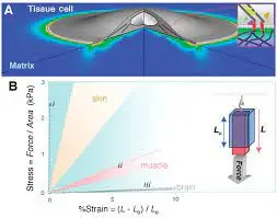
Such a probe would allow a better understanding of how these properties influence diseases like arteriosclerosis or cancer, or how an embryo develops, for example. To tackle this challenge, Wang and graduate student Erfan Mohagheghian looked for ways to alter the mechanical characteristics of a probe. But he said he wanted to develop a more universal probe that could tackle both at once. Such a probe would allow a better understanding of how these properties influence diseases like arteriosclerosis or cancer, or how an embryo develops, for example. To tackle this challenge, Wang and graduate student Erfan Mohagheghian looked for ways to alter the mechanical characteristics of a probe after injecting it into the tissue of interest.
Study co-author Kristi Anseth is a professor of chemical and biological engineering at the University of Colorado, Boulder. The team developed a precise method for embedding a magnetic “microcross” into a rigid PEG hydrogel. By subjecting those tissues to an electromagnetic field, the scientists activated the probes to exert various stresses on the tissues. The probes gave precise information about both the tissue stiffness and traction. While malignant tumors may become stiffer in response to surrounding tissues, the cancer cells do not change their tractions.
Researchers at the Chinese Academy of Sciences and Huazhong University of Science and Technology in Wuhan, China, have developed a magnetic microrobot that can detect force oscillations. Such oscillations correspond with the patterning of organs, tissues and limbs as animals develop from single cells into complex tissues.
The Virginia Tech Center for Vehicle Systems and Safety (CVeSS) and the Railway Technologies Laboratory want to harness the energy created by moving trains and transform that energy into usable electricity. 76% of the total miles on American railroad tracks are in rural areas that lack the electricity required for operating smart rail systems.
Researchers at CVeSS set about coming up with a more durable solution that would provide energy to these devices, deter theft, and require minimal maintenance.
Research in motion
As the wheels of the train pass over the rail, the bars pushes down a metal bar, triggering a series of gears. Those gears rotate a generator and produces electricity, this energy produce can be stored in a battery.
After developing this viable idea, the team next created a prototype. The researchers successfully tested the device in the lab, and Ahmadian started conversations about the technology with familiar industry partners.
Norfolk-Southern agreed to host the deployment of the new rail on a section of its track this past August. Since that rollout, the CVeSS team has been collecting data to determine the amount of power that can be generated and the best ways to optimize the device’s design.
A Rail With Purpose
For every wheel of the train that goes by, we are harvesting 15 to 20 watts of power, says Ahmadian.
“If we have a long train with maybe 200 railcars, that’s 800 wheels, making 1.6 kilowatts,” he says. The ability to monitor the track with that technology is mostly absent, not because we don’t have the technology, but because it is difficult to bring power to remote locations.
Conclusion
The Virginia Tech Center for Vehicle Systems and Safety (CVeSS) and Railway Technologies Laboratory want to harness the energy created by moving trains and transform that energy into usable electricity. A new kind of high-tech tie, placed underneath the rail, is topped with a heavy metal bar mounted on a spring.
This project design is an IoT (Internet of Things), smart home automation and surveillance project that was based on using Telegram and Blynk servers to host home automation controls and surveillance procedures. The project is designed and programmed around a two-bedroom flat model home. The entrance has a motion triggered visitor camera made from the famously low cost ESP32 cam. Each of the bedrooms, including the sitting room, lightings and load points are controlled remotely via an IoT Blynk dashboard. The system is programmed to to alert the owner of the home of any visitor at the entrance door through a telegram alert. The project design is meant to work as follows, in summary:
Use the motion sensor to trigger a telegram alert that is sent to your phone any time a visitor is at the entrance door.
The owner can put out his/her phone on such notification and open the Blynk, from where
Controls the home appliances through the Blynk app dashboard and from there, take another view of the visitor, if it is someone he/she wants to come inside his house, he can open the door, for the person remotely.
Captures an image of picture of the visitor at the entrance door and displays it on the image widget on telegram and send a backup copy to the telegram app channel.
The system also allow for auto opening of the doors to each rooms form the Blynk app driectly.
The speed control for ventilations from all of the fans in the room are controlled on the Blynk app.
All load points that is AC sockets are controlled remotely too from the app.
Introduction
Home automation refers to the use of technology to control and automate various aspects of a home, such as lighting, heating, and appliances. This can be done through the use of smart devices, such as smartphones or tablets, which can be used to remotely control and monitor these systems. Home automation systems can also be integrated with other smart devices, such as voice assistants, to provide a more seamless and convenient user experience.
Home surveillance, on the other hand, refers to the use of technology to monitor and secure a home. This can be done through the use of cameras and other sensors, which can be used to detect and deter intruders, as well as to monitor the comings and goings of people and pets. Some home surveillance systems also include features such as motion detection and facial recognition, which can be used to alert homeowners of potential threats and to automatically trigger an alarm.
When combined, home automation and surveillance can provide a powerful and comprehensive solution for securing and managing a home. Smart cameras, for instance, can be integrated with home automation systems to allow homeowners to monitor their home remotely and to control lighting and appliances in response to motion detection. Similarly, home automation systems can be integrated with surveillance systems to automatically trigger an alarm when an intrusion is detected.
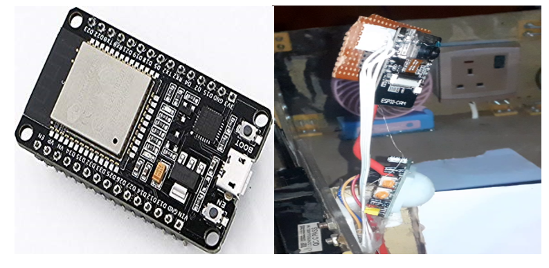
The two dev boards used in this project was ESP32 dev board and ESP32 Cam
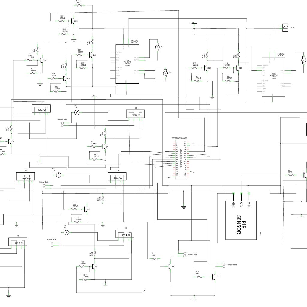
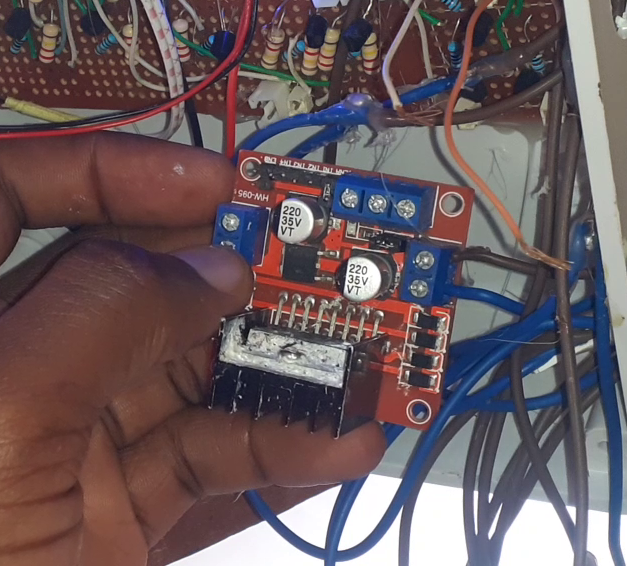
The circuit diagram is divided into two parts, namely; the IoT home automation part that is built around the famous ESP32 development board. And the IoT surveillance system part that is built around the ESP32 Cam development board. The system is powered by a 12V power supply to run the three Direct Current (DC) motors that are connected to to the motor driver module L293. Since the ESP32 development board works on 5V, a DC-DC buck converter was needed to step this 12V to 5V.
The motor driver module
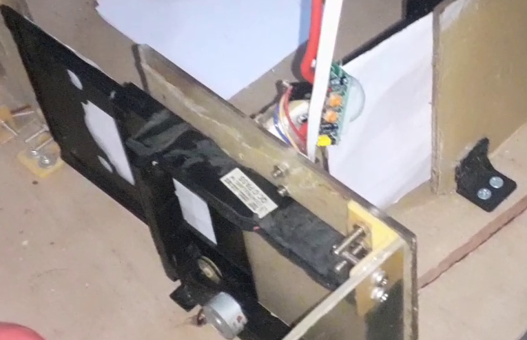
The two DC motor driver modules are powered by the 12V power supply, motor driver module one was used to drive two model doors used for the rooms other than the sitting room. The other motor driver was used to control the movement of the door leading to the sitting room. The directional movement of these DC motors would cause opening and closing effects on the doors, making them sliding doors that can be controlled remotely via an app.
The sliding doors were made from two DVD motor tray mechanisms
The first motor driver module was connected 4 input pins to control the two DC motors (model doors). This is shown in the circuit diagram above. These input pins come from the ESP32 dev board. Whereas the second motor driver module as only 2 input connection to the ESp32 dev board. This is because it only controls one model door which is the entrance door to the sitting room.
The circuit diagram shows that a logic inverter was made from a simple transistor circuit that allowed the motor driver to receive 5V HIGH and 0V LOW from the ESP32 Dev board rather than the usual 3.3V and 0V logic level.
The Actuators
These are mainly made of solid state relay modules designed with logic inverters that would help switch the states of the AC light bulbs and the load point AC sockets. The relay module was custom built by us to be a 6-channel relay module that controls the 3 load point sockets and the the 3 lightening bulbs in the rooms.
Since the solid state relay works on 5V logic, the ESP32 dev board can only output 3.3V logic. We also used the logic inverter/amplifier to convert this to 5V. This also meant however that, when the ESP32 dev board sends an output of 3.3V, the inverter inverts this to give 0V. Whereas when the ESP32 dev board sends a logic output, the inverter converts this to 5V high.
The AC actuators are wired to in such a way that the neutral are connected together while the Live (L) wires are connected through the solid state relay. This is shown in the circuit diagram shown above. The solid state relay is energized when the user presses the button on the app or sends a command through the Telegram app.
The Surveillance System
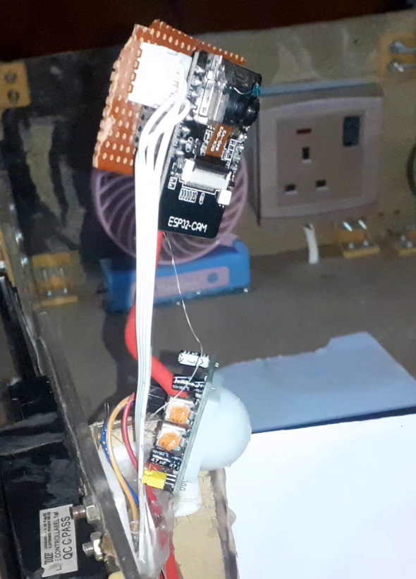
This part of the project was made with the ESP32 Cam and the PIR motion sensor. The ESP32 Cam was connected to the output signal pin of the PIR sensor so that once it senses the presence of a person, it can trigger the ESP32 Cam to take a picture. Once this picture is taken, it is sent to the Telegram as a cloud based backup and also a copy is sent to the Blynk image widget.
Designing The Control Blynk App
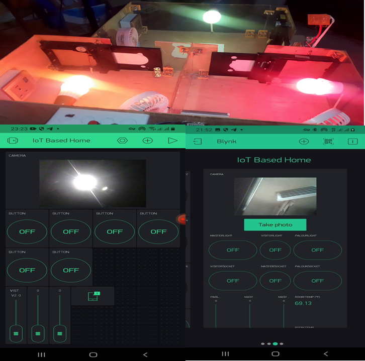
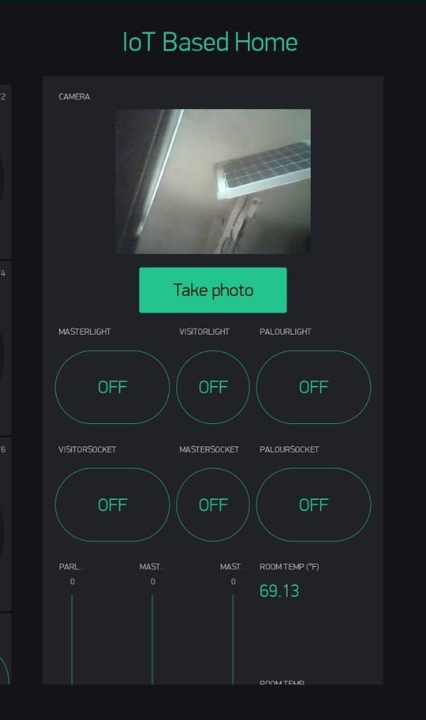
This project used the Blynk legacy app but if you want to use the latest version of Blynk, contact us here. See this blog post on how to create an app on the Blynk platform. The design here used the image widget where the images taken when the “take photo” button is pressed. It displays the picture taken by the ESP32 Cam on this app. Thereby letting the user know who is at the entrance door.
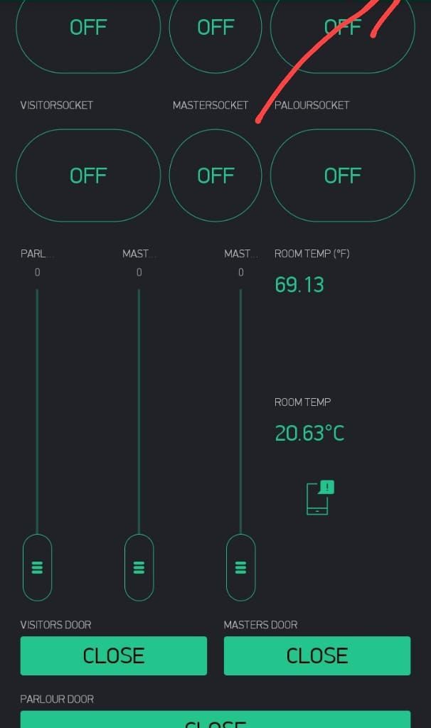
The app design has six (6) control pushbuttons for the home appliances connected in the model house. The first upper three pushbuttons were used to control the lightnings in the rooms. While the lower 3 pushbuttons were used to control the loadpoint sockets.
Three (3) slider widgets were used to control the speed of the fans that are place in the room. The slier widgets keeps the fan speeds at maximum when the slider buttons are place at the very vertical tops. Whereas when they are moved down to the bottom, it reduces the fans’ speeds until they come to a stop.
To control the direction of the doors in the rooms, three other pushbuttons were added. These pushbuttons are placed horizontally and are much larger in side than previous one. These pushbuttons were labelled “OPEN ” and “CLOSE”. When the door is closed, the pushbutton widget would display, Open. and it is opened, the pushbutton widget would display Close.
The app design also has an app notifier and a room temperature display widget that can display the room temperature in the house. This is shown in the picture above as the temperature is both displayed in both Celsius and Fahrenheit degrees.
The Telegram Bot App
The project design used the Telegram bot to alert the user of any visitor at the entrance door and also to save the captured picture of such visitor with timestamp as backup. To create this Telegram bot is quite easy.
The BotFather bot
For the project to have authorized user access, a telegram bot was created to have the choice of arming and disarming the project design. To do this we had to create a bot using botFather.
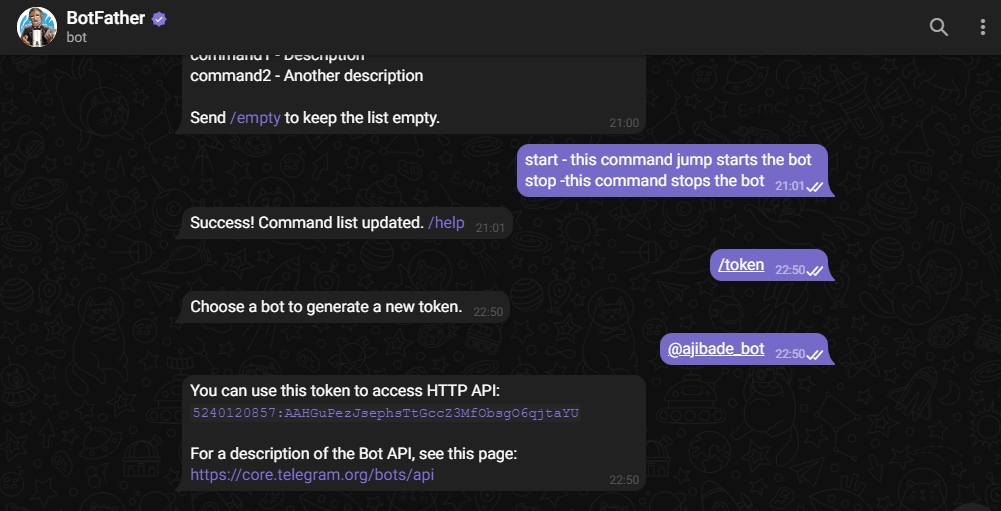
Creating a new bot named ajibade_bot using botfather
The Botfather is a chat bot that allowed us to create our own custom bot. The bot father had commands that would start it and end the chat with users. When it is sent “/start”, it returns some options from which new commands can be sent. This allowed us to get the API key when we put in the program we uploaded into the ESP32 Cam and ESP32. With this API key, we can assign admin role to users who have access to this bot. such that they can send commands to it and receive feedbacks remotely.
Modelling the Project Design
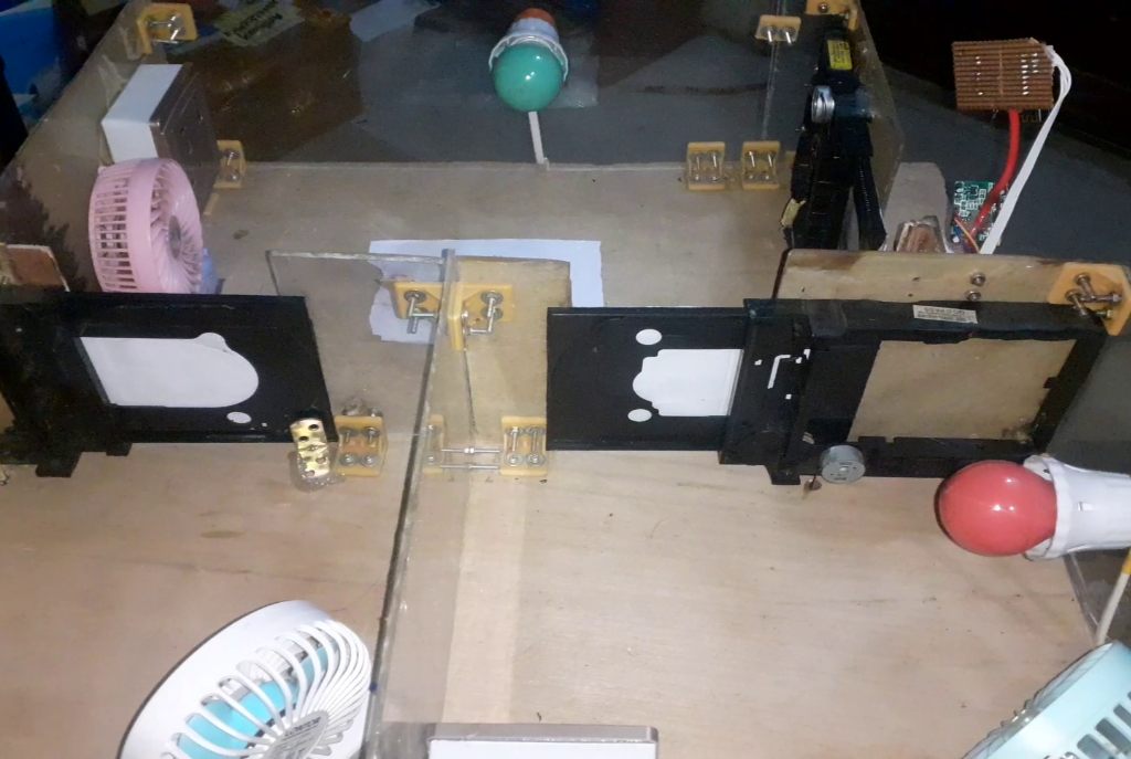
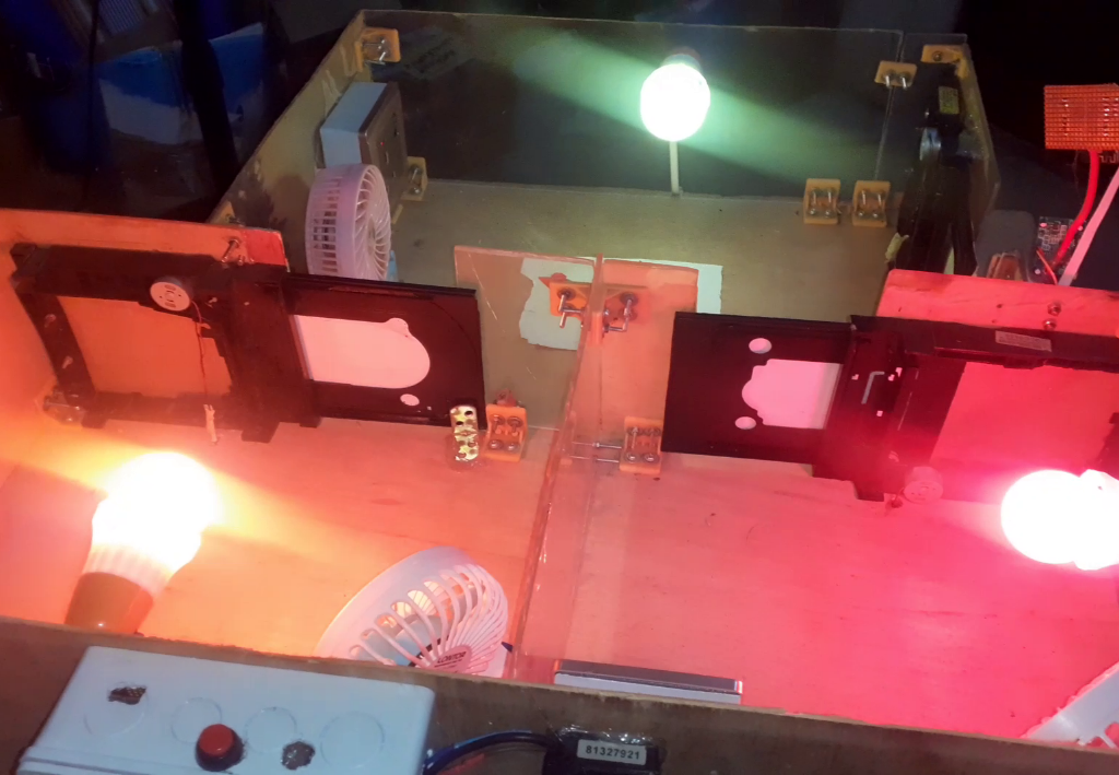
The home model for the project design
The IoT home automation and surveillance system was constructed on a stripboard by assembling the components accordingly before soldering with solder and soldering iron. The 3D model was done on a flat board with dimensions measured out accordingly as shown in the picture above.
The model house when tested
The demo modelling was done on a plywood board. For the demonstration of this project, a plywood of thickness 0.5” (inches) with dimension 40cm by 28.5cm ; was cut out, its surface further smoothened.
Casing the Control Box
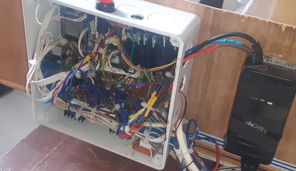
The casing was made to be a house model shown in the figure 3.25 below. The casing encased the most of the components and modules use in the project design. It was made from a (6×6)” pattress box. The power supply adaptor was screwed to the side so as to get easy access to DC power supply into the box.
The Arduino Source Code
The Arduino source code for this project design is into parts namely, the Arduino source for the ESP32 Dev board and the Arduino source code for the ESP32 Cam board.
#include <Arduino.h>
#include "esp_camera.h"
#include <WiFi.h>
#include <WiFiClient.h>
#include <WiFiClientSecure.h>
#include "soc/soc.h"
#include "soc/rtc_cntl_reg.h"
#include <BlynkSimpleEsp32.h>
#include <UniversalTelegramBot.h>
#include <ArduinoJson.h>

const char* ssid = "AncII";
const char* password = "eureka26";
String chat_id;


//auth key sent by Blynk
char auth[] = "ghGtzWtTrA9-0uQWOps2GtHqBFWa1tlQ";
// Initialize Telegram BOT
String BOTtoken = "5240120857:AAHGuPezJsephsTtGccZ3MfObsgO6qjtaYU";  // your Bot Token (Get from Botfather)


// Select camera model
#define CAMERA_MODEL_AI_THINKER // Has PSRAM
#include "camera_pins.h"
#define PIR 13
#define LED 4

String CHAT_ID = "746723461";

bool sendPhoto = false;
bool armed = false;
bool flashState = 0;

WiFiClientSecure clientTCP;
UniversalTelegramBot bot(BOTtoken, clientTCP);

//Checks for new messages every 1 second.
int botRequestDelay = 1000;
unsigned long lastTimeBotRan;

String local_IP;
void startCameraServer();


void configInitCamera(){
  camera_config_t config;
  config.ledc_channel = LEDC_CHANNEL_0;
  config.ledc_timer = LEDC_TIMER_0;
  config.pin_d0 = Y2_GPIO_NUM;
  config.pin_d1 = Y3_GPIO_NUM;
  config.pin_d2 = Y4_GPIO_NUM;
  config.pin_d3 = Y5_GPIO_NUM;
  config.pin_d4 = Y6_GPIO_NUM;
  config.pin_d5 = Y7_GPIO_NUM;
  config.pin_d6 = Y8_GPIO_NUM;
  config.pin_d7 = Y9_GPIO_NUM;
  config.pin_xclk = XCLK_GPIO_NUM;
  config.pin_pclk = PCLK_GPIO_NUM;
  config.pin_vsync = VSYNC_GPIO_NUM;
  config.pin_href = HREF_GPIO_NUM;
  config.pin_sscb_sda = SIOD_GPIO_NUM;
  config.pin_sscb_scl = SIOC_GPIO_NUM;
  config.pin_pwdn = PWDN_GPIO_NUM;
  config.pin_reset = RESET_GPIO_NUM;
  config.xclk_freq_hz = 20000000;
  config.pixel_format = PIXFORMAT_JPEG;

  //init with high specs to pre-allocate larger buffers
  if(psramFound()){
    config.frame_size = FRAMESIZE_UXGA;
    config.jpeg_quality = 10;  //0-63 lower number means higher quality
    config.fb_count = 2;
  } else {
    config.frame_size = FRAMESIZE_SVGA;
    config.jpeg_quality = 12;  //0-63 lower number means higher quality
    config.fb_count = 1;
  }

  // camera init
  esp_err_t err = esp_camera_init(&config);
  if (err != ESP_OK) {
    Serial.printf("Camera init failed with error 0x%x", err);
    delay(1000);
    ESP.restart();
  }

  // Drop down frame size for higher initial frame rate
  sensor_t * s = esp_camera_sensor_get();

  if (s->id.PID == OV3660_PID) {
    s->set_vflip(s, 1); // flip it back
    s->set_brightness(s, 1); // up the brightness just a bit
    s->set_saturation(s, -2); // lower the saturation
  }

  s->set_framesize(s, FRAMESIZE_CIF);  //UXGA|SXGA|XGA|SVGA|VGA|CIF|QVGA|HQVGA|QQVGA
}


void handleNewMessages(int numNewMessages) {
  Serial.print("Handle New Messages: ");
  Serial.println(numNewMessages);
for (int i = 0; i < numNewMessages; i++) {
     chat_id = String(bot.messages[i].chat_id);
    if (chat_id != CHAT_ID){
      bot.sendMessage(chat_id, "Unauthorized user", "");
      continue;
    }

    // Print the received message
    String text = bot.messages[i].text;
    Serial.println(text);

    String from_name = bot.messages[i].from_name;
    if (text == "/start") {
      armed = true;
      Serial.println("system armed");
      String welcome = "Welcome , " + from_name + "\n";
      welcome += "Use the following commands to interact with the ESP32-CAM \n";
      welcome += "/photo : takes a new photo\n";
      welcome += "/flashLightOn : turn on flash \n";
      welcome += "/flashLightOff : turn off flash \n";
      bot.sendMessage(CHAT_ID, welcome, "");
    }


    if (text == "/flashLightOn") {
      digitalWrite(LED, HIGH);
      Serial.println("flash LED on");
      String flashStatus = "Sir " + from_name + "\n";
      flashStatus += "flash of ESP32-CAM turned on \n";
      bot.sendMessage(CHAT_ID, flashStatus, "");
    }

    if (text == "/flashLightOff") {
      digitalWrite(LED, LOW);
      Serial.println("flash LED off");
      String flashStatus = "Sir " + from_name + "\n";
      flashStatus += "flash of ESP32-CAM turned off \n";
      bot.sendMessage(CHAT_ID, flashStatus, "");
    }

    if (text == "/photo") {
            sendPhoto = true;
      Serial.println("New photo request");
    }
  }
}


void takePhoto(){
  digitalWrite(LED, HIGH);
  delay(200);
  uint32_t randomNum = random(50000);
  Serial.println("http://"+local_IP+"/capture?_cb="+ (String)randomNum);
  Blynk.setProperty(V1, "urls", "http://"+local_IP+"/capture?_cb="+(String)randomNum);
  digitalWrite(LED, LOW);
  delay(1000);
}


BLYNK_WRITE(V5){
  // Set incoming value from pin V0 to a variable
  int buttonValue = param.asInt();
  Serial.println(buttonValue);
  if(buttonValue == 1){
    Serial.println("Capture Photo");
  takePhoto();
  delay(3000);
  Serial.println("sending photo to telegram");
   sendPhoto = true;
    }

}


String sendPhotoTelegram() {
  const char* myDomain = "api.telegram.org";
  String getAll = "";
  String getBody = "";

  camera_fb_t * fb = NULL;
  fb = esp_camera_fb_get();
  if(!fb) {
    Serial.println("Camera capture failed");
    delay(1000);
    ESP.restart();
    return "Camera capture failed";
  }

  Serial.println("Connect to " + String(myDomain));


  if (clientTCP.connect(myDomain, 443)) {
    Serial.println("Connection successful");

    String head = "--Anc\r\nContent-Disposition: form-data; name=\"chat_id\"; \r\n\r\n" + CHAT_ID + "\r\n--Anc\r\nContent-Disposition: form-data; name=\"photo\"; filename=\"esp32-cam.jpg\"\r\nContent-Type: image/jpeg\r\n\r\n";
    String tail = "\r\n--Anc--\r\n";

    uint16_t imageLen = fb->len;
    uint16_t extraLen = head.length() + tail.length();
    uint16_t totalLen = imageLen + extraLen;

    clientTCP.println("POST /bot"+BOTtoken+"/sendPhoto HTTP/1.1");
    clientTCP.println("Host: " + String(myDomain));
    clientTCP.println("Content-Length: " + String(totalLen));
    clientTCP.println("Content-Type: multipart/form-data; boundary=Anc");
    clientTCP.println();
    clientTCP.print(head);

    uint8_t *fbBuf = fb->buf;
    size_t fbLen = fb->len;
    for (size_t n=0;n<fbLen;n=n+1024) {
      if (n+1024<fbLen) {
        clientTCP.write(fbBuf, 1024);
        fbBuf += 1024;
      }
      else if (fbLen%1024>0) {
        size_t remainder = fbLen%1024;
        clientTCP.write(fbBuf, remainder);
      }
    }

    clientTCP.print(tail);

    esp_camera_fb_return(fb);

    int waitTime = 10000;   // timeout 10 seconds
    long startTimer = millis();
    boolean state = false;

    while ((startTimer + waitTime) > millis()){
      Serial.print(".");
      delay(100);
      while (clientTCP.available()) {
        char c = clientTCP.read();
        if (state==true) getBody += String(c);
        if (c == '\n') {
          if (getAll.length()==0) state=true;
          getAll = "";
        }
        else if (c != '\r')
          getAll += String(c);
        startTimer = millis();
      }
      if (getBody.length()>0) break;
    }
    clientTCP.stop();
    Serial.println(getBody);
  }
  else {
    getBody="Connected to api.telegram.org failed.";
    Serial.println("Connected to api.telegram.org failed.");
  }
  return getBody;
}

void setup(){
  WRITE_PERI_REG(RTC_CNTL_BROWN_OUT_REG, 0);
  // Init Serial Monitor
  Serial.begin(115200);
  Serial.setDebugOutput(true);

  // Set LED Flash as output
  pinMode(LED, OUTPUT);
  pinMode(PIR, INPUT_PULLUP);


  // Config and init the camera
  configInitCamera();

  // Connect to Wi-Fi

  WiFi.mode(WIFI_STA);
  Serial.println();
  Serial.print("Connecting to ");
  Serial.println(ssid);
  WiFi.begin(ssid, password);
  clientTCP.setCACert(TELEGRAM_CERTIFICATE_ROOT); // Add root certificate for api.telegram.org
  while (WiFi.status() != WL_CONNECTED) {
    Serial.print(".");
    delay(500);
  }
  Serial.println();
  Serial.print("ESP32-CAM IP Address: ");
  Serial.println(WiFi.localIP());


  startCameraServer();
 Serial.print("Camera Ready! Use 'http://");
 Serial.print(WiFi.localIP());
 local_IP = WiFi.localIP().toString();
 Serial.println("' to connect");
  Blynk.begin(auth, ssid, password);


}


void motionSensor(){
    if(digitalRead(PIR) == LOW){
  Serial.println("Send Notification");
  Blynk.notify("Motion Detected, Person Is At The Door.");
  bot.sendMessage(chat_id, "Motion Detected, Person Is At The Door", "");
  Serial.println("alert Sent");
  delay(3000);
  }

}

void loop() {
   Blynk.run();
  BLYNK_WRITE(V5);
  motionSensor();


   if (sendPhoto) {
    Serial.println("Preparing photo");
    sendPhotoTelegram();
     delay(3000);
    sendPhoto = false;
  }


  if (millis() > lastTimeBotRan + botRequestDelay)  {
    int numNewMessages = bot.getUpdates(bot.last_message_received + 1);
    while (numNewMessages) {
      Serial.println("got response");
      handleNewMessages(numNewMessages);
      numNewMessages = bot.getUpdates(bot.last_message_received + 1);
    }
    lastTimeBotRan = millis();
  }
}
The Result
Conclusion
In this IoT home automation and surveillance system project design using Arduino, Blynk and Telegram app. We have successfully, when in the “armed mode”, used the ESP32 Cam and the PIR sensor module to auto-detect and take surveillance pictures of visitors at an entrance door and alert the user of such events on the Telegram app. The user can open a full custom dashboard on the Blynk app, where he can choose to allow the visitor inside by opening the door with his app. Tis app also allows us to control other things like fan speed, lightnings in the house and also display the room temperature and access control to all doors.
What do you think of such DIY design on Home Automation and surveillance? is it worth the effort? Let us know in the comment section below.
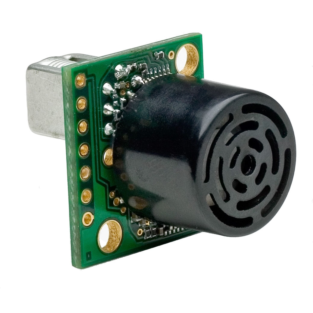
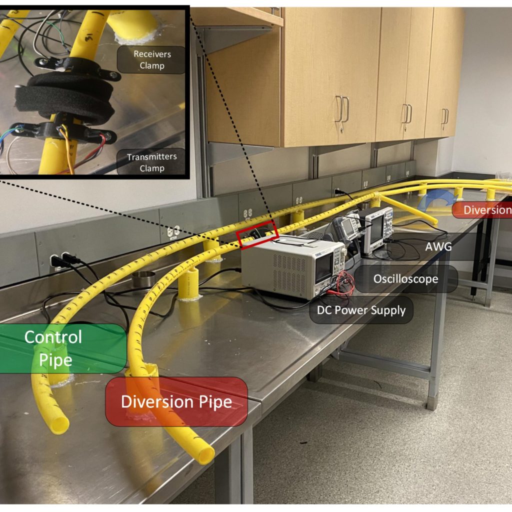
Researchers at UBC Okanagan are looking into a novel technique for monitoring subterranean gas pipes with sophisticated sensors (ultrasonic sensors) that could make it simple to spot flaws, anomalies, and even a diversion in household natural gas connections.
Master of applied science student Abdullah Zayat claims little has been done on the widely used polyethylene pipe that transports natural gas to homes. steel pipes using techniques like radiography, ultrasonic testing, visual inspection, and ground-penetrating radar.
Early detection of structural degradation is essential to maintaining safety and integrity, says Zayat Assistant Professor of Electrical Engineering. He and his supervisor Dr. Anas Chaaban tested a technique that allows for the inspection of HDPE pipes with ultrasonic sensors. The new monitoring method limits the likelihood of gas diversions.
Previous research has studied the inspection of metallic structures using ultrasonic-guided waves (UGWs). But this type of testing has not been done to inspect non-metallic structures such as HDPE pipelines.”Given the concealed nature of underground pipes, it is very challenging to inspect them.
Existing solutions include ground penetrating radar and endoscope cameras, which are both invasive and expose inspectors to potential risk from the suspects. As a result, it is better to use non-invasive methods to inspect pipes.”
UGW sensing is a waveguide ultrasonic underwater pipe inspection system that can inspect more than 100 meters of pipeline from a single test location. It uses the structure of the pipe itself as an ultrasonic waveguide to inspect underground, insulated and underwater pipelines.
This type of detection system is unique because the sensors clamp onto the exposed portion of the pipe and connect to the section of pipe that emerges above the ground where it connects to the meter.
While the technology is still in its early stages, Dr. Chaaban notes that the majority of this current research involved the development and assessment of a deep-learning algorithm for detecting diversions in pipes. The sensor (ultrasonic sensors) clamp onto the exposed portion of the pipe and connect to the section of pipe that emerges above the ground where it connects to the meter. The system has 90 percent accuracy when one receiving sensor is used and nearly 97 percent accuracy with two receiving sensors. Future use of the sensors may include inspection of buried, insulated, and underwater pipelines.
Inspired by sea cucumbers, the robots are magnetic and can conduct electricity. Researchers embedded magnetic particles in metal with a very low melting point (29.8 °C). Magnetic particles make the material responsive to an alternating magnetic field. “Giving the human-like robot the ability to switch between liquid and solid states endows them with more functionality,” says Chengfeng Pan, an engineer at The Chinese University of Hong Kong who led the study.
The team created the new phase-shifting material—dubbed a “magnetoactive solid-liquid phase transitional machine”—by embedding magnetic particles in gallium, a metal with a very low melting point (29.8 °C).”The magnetic particles here have two roles,” says senior author and mechanical engineer Carmel Majidi of Carnegie Mellon University. “One is that they make the material responsive to an alternating magnetic field, so you can, through induction, heat up the material and cause the phase change. But the magnetic particles also give the robots mobility and the ability to move in response to the magnetic field.”
This is in contrast to existing phase-shifting materials that rely on heat guns, electrical currents, or other external heat sources to induce solid-to-liquid transformation. The new material also boasts an extremely fluid liquid phase compared to other phase-changing materials, whose “liquid” phases are considerably more viscous. Before exploring potential applications, the team tested the material’s mobility and strength in a variety of contexts.
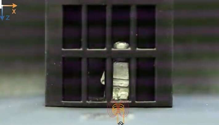
In one video, a robot shaped like a person liquifies to ooze through a grid after which it is extracted and remolded back into its original shape. “Now, we’re pushing this material system in more practical ways to solve some very specific medical and engineering problems,” says Pan.A video of a robot delivering a drug into a model stomach.
In one experiment, a robot shaped like a person liquefies to ooze through a grid after which it is extracted and remolded back into its original shape. They also demonstrate how the material could work as smart soldering robots for wireless circuit assembly and repair (by oozing into hard-to-reach circuits and acting as both solder and conductor) The team used the robots to remove foreign object from a model stomach and deliver drugs into the same model stomach.
“Future work should further explore how these robots could be used within a biomedical context,” says Majidi. “What we’re showing are just one-off demonstrations, proofs of concept, but much more study will be required to delve into how this could actually be used for drug delivery,” Majidi says.
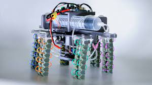
In the College of Engineering, electrical and computer engineering assistant professor Kirstin Petersen works. Her team developed a system of fluid-driven actuators that enable soft robots to achieve more complex motions. Their paper, “Harnessing Nonuniform Pressure Distributions in Soft Robotic Actuators,” was published Jan. 20 in Advanced Intelligent Systems.
soft robot
“Soft robots have a very simple structure, but can have much more flexible functionality than their rigid cousins.” “They’re sort of the ultimate embodied intelligent robot,” Petersen said. “Soft robots are sort of the ultimate embodied intelligent robot,” Petersen says.
“Most soft robots these days are fluid-driven. In the past, most people have looked at how we could get extra bang for our bucks by embedding functionality into the robot material, like the elastomer. Instead, we asked ourselves how we could do more with less by utilizing how the fluid interacts with that material.”
Traditionally, a soft robot’s fluid-driven actuator—i.e., the part the moves, such as a limb—functions when evenly pressurized fluid flows through an elastomer bladder or bellow. They connected a series of bellows with slender tubes, running in a pair of parallel columns, all in a closed system. Tiny tubes induce viscosity, which causes the pressure to be distributed unevenly, bending the actuator. That would normally be a problem, but the team found a clever way to take advantage of it.
Matia developed a full descriptive model that could predict the actuator’s possible motions and anticipate how different input pressures, geometries, and tube and bellow configurations achieve them—all with a single fluid input. It can do so without the multiple inputs and complex feedback control that previous methods required, the researchers say.
“We detailed the full complement of methods by which you can design these actuators for future applications,” Petersen said. “We detailed the full complement of methods by which you can design these actuators for future applications,” she said.
Conclusion
Researchers at Cornell University’s College of Engineering have developed a system of fluid-driven actuators that enable soft robots to achieve more complex motions. The team’s paper, “Harnessing Nonuniform Pressure Distributions in Soft Robotic Actuators,” was published Jan. 20 in Advanced Intelligent Systems. “This is basically a whole new subfield of soft robotics,” researcher Angharad Petersen says.