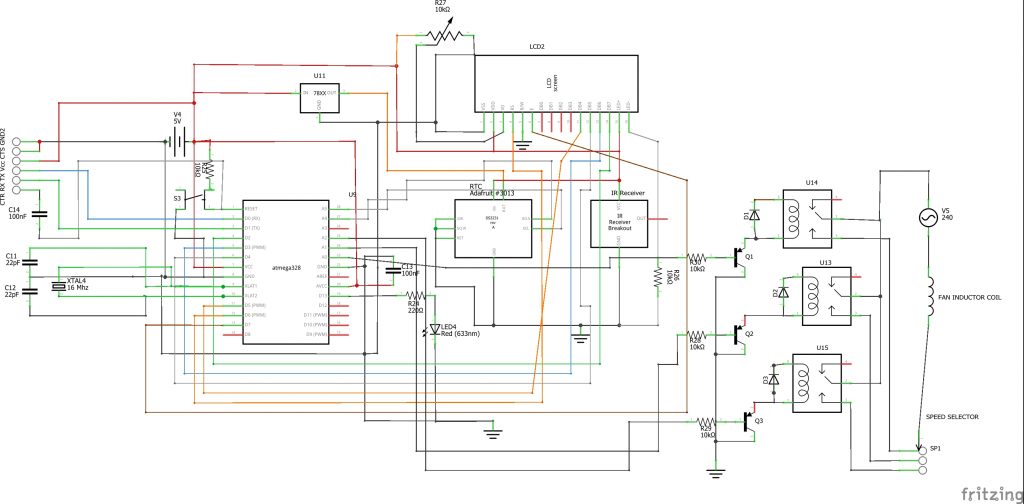
Following the circuit diagram, we built the standalone development board around the Atmega328P-U microcontroller. For other projects that used Atmega328P-PU microcontroller, check out: Atmega328P-U projects
So here, the atmega328P-U microcontroller unit (MCU) is programmed using the FTDI ISP programmer as shown above. We used a DS3231 type of RTC to keep and set our time. We also used a PIR sensor to detect the motion. The connection is set such that the serial clock pin (SCL) and the serial data pin (SDA) of the RTC are connected to analog pin 5 (A5) and analog pin 4 (A4) of the MCU, respectively. The PIR output is connected to the digital pin 10 of the Atmega328P-U.
Next that catches our interest is the 16×4 LCD connection. As shown in the circuit diagram, we are using 4-bit connection mode (4 wire type connection). We connected out Register select (RS) to D3 of the MCU, the enable pin (E) to D4, and the four data pins to digital pins 8 through 5.
Note: If you are using a power supply that has DC output above 5V, you have to use a voltage regulator as shown in the circuit diagram to buck it down to 5V since the MCU uses 5V DC output. but ensure that your 5V meets up to 3A. Otherwise, during relay switch, the LCD screen may scatter and start misbehaving. Also, if you don’t use 5V DC supply, the whole system would end up getting fried.
Now, to switch the states of the AC standing fan, we need a 3-channel relay module to change the speed controls automatically.
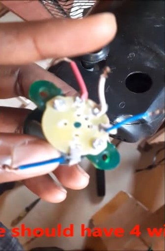
Here we disconnected the normal speed selector switch found on the standing fan and extended it out with more wires. Then the AC live wire is connected to the common relay, while the respective speed lines are connected to the other three as shown in the picture above. The neutral line of the AC is connected to the neutral of the fan induction coil.
After the connection has been made, the PIR sensor and the RTC is connected too to the MCU board. The LCD module is connected to its header pin. Next is to program the MCU. Copy the code below into your Arduino IDE.
#include <Wire.h>
#include <RTClib.h>
#include <EEPROM.h>
#include <IRremote.h>
#include <LiquidCrystal.h>
LiquidCrystal lcd(3, 4, 8, 7, 6, 5);
RTC_DS3231 rtc;
char daysOfTheWeek[7][12] = {"Sunday", "Monday", "Tuesday", "Wednesday", "Thursday", "Friday", "Saturday"};
#define speed1 A0
#define speed2 A1
#define speed3 A2
int RECV_PIN = 2;
const int PIR = 10;
unsigned long count = 0;
int state = LOW;
int currentState = 0;
int previousState = 0;
int sensor_count = 0;
int timer = 0;
int ts = 50;
int tc = ts;
int sc = 10;
int fail = 0;
int ms = 50;
unsigned long pm = 0;
const long interval = ms;
boolean logic;
byte val0 = EEPROM.read(0);
byte val1 = EEPROM.read(1);
byte val2 = EEPROM.read(2);
int ontime = val1;
int offtime = val2;
int menu = 0;
int pause = 50;
int rtcDAY, rtcMONTH, rtcYEAR, rtcHOUR, rtcMIN, rtcSEC;
int minus = 0;
int plus = 0;
int fan = 0;
String remote;
String stat = "";
String SPEED = "";
IRrecv irrecv(RECV_PIN);
decode_results results;
void page(){
DateTime now = rtc.now();
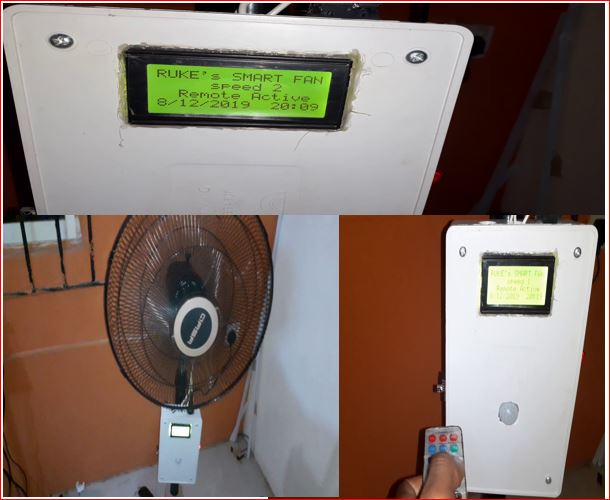
lcd.setCursor(0, 0);
lcd.print("RUKE's SMART FAN");
lcd.setCursor(0, 1);
lcd.print(SPEED);
lcd.setCursor(0, 2);
lcd.print(stat);
lcd.setCursor(0, 3);
lcd.print(now.day(), DEC);
lcd.print('/');
lcd.print(now.month(), DEC);
lcd.print('/');
lcd.print(now.year(), DEC);
lcd.print(" ");
lcd.print(now.hour(), DEC);
lcd.print(':');
lcd.print(now.minute(), DEC);
}
void fanOff(){
//turn the fan off
analogWrite(speed1, 255);
analogWrite(speed2, 255);
analogWrite(speed3, 255);
SPEED = " FAN OFF ";
}
void spd1(){
//turn the fan off
analogWrite(speed1, 0);
analogWrite(speed2, 255);
analogWrite(speed3, 255);
SPEED = " speed 1 ";
}
void spd2(){
//turn the fan off
analogWrite(speed1, 255);
analogWrite(speed2, 0);
analogWrite(speed3, 255);
SPEED = " speed 2 ";
}
void spd3(){
//turn the fan off
analogWrite(speed1, 255);
analogWrite(speed2, 255);
analogWrite(speed3, 0);
SPEED = " speed 2 ";
}
void SenSe(){
unsigned long cm = millis();
unsigned long rr = cm - pm;
if(rr > interval){
if(digitalRead(PIR)==HIGH){
sensor_count = sensor_count + 1;
}
timer = timer + 1;
pm = cm;
if(timer >= tc){
if((sensor_count >= sc) && (tc >= ts)){
spd2();
tc = 0;
fail = 0;
}
else{
fail = fail + 1;
tc = ts;
//interval = ms;
}
timer = 0;
sensor_count = 0;
}
}
if(fail > 20){
fail = 0;
fanOff();
}
}
void setup() {
// put your setup code here, to run once:
Serial.begin(9600);
lcd.begin(16, 4);
pinMode(speed1, OUTPUT);
pinMode(speed2, OUTPUT);
pinMode(speed3, OUTPUT);
pinMode(PIR,INPUT);
if (! rtc.begin()) {
lcd.setCursor(0, 0);
lcd.print("Can't find RTC");
delay(3000);
while (1);
}
if (rtc.lostPower()) {
lcd.setCursor(0, 0);
lcd.print("RTC lost power!");
// following line sets the RTC to the date & time this sketch was compiled
rtc.adjust(DateTime(F(__DATE__), F(__TIME__)));
delay(3000);
}
// In case the interrupt driver crashes on setup, give a clue
// to the user what's going on.
Serial.println("Enabling IRin");
irrecv.enableIRIn(); // Start the receiver
Serial.println("Enabled IRin");
fanOff();
}
void loop() {
// put your main code here, to run repeatedly:
DateTime now = rtc.now();
rtcHOUR = now.hour(), DEC;
if (irrecv.decode(&results)){
remote = String(results.value, HEX);
if(remote == "511dbb"){
menu = 1;
}
Serial.println(menu);
Serial.println(fan);
Serial.println(remote);
irrecv.resume(); // Receive the next value
}
if((rtcHOUR >= ontime) && (rtcHOUR <offtime))//Comparing the current time with the Alarm time
{
stat = " Auto Mode ";
SenSe();
}
else{
if(remote == "c101e57b"){
fanOff();
}
if(remote == "9716be3f"){
spd1();
}
if(remote == "3d9ae3f7"){
spd2();
}
if(remote == "6182021b"){
spd3();
}
stat = " Remote Active ";
}
if(menu < 1){
page();
}
menu = constrain(menu, 0, 5);
switch(menu){
case 1:
lcd.setCursor(0, 0);
lcd.print("**Control MENU** ");
lcd.setCursor(0, 1);
lcd.print(">1. FAN ON Time ");
lcd.setCursor(0, 2);
lcd.print(" 2. FAN OFF Time ");
lcd.setCursor(0, 3);
lcd.print(" 3. EXIT MENU ");
if(remote == "a3c8eddb"){
menu++;
if(menu > 3){
menu = 1; }
}
if(remote == "f076c13b"){
menu--;
if(menu < 1){
menu = 3; }
}
if(remote == "e5cfbd7f" && menu == 1){
menu = 4;
}
break;
case 2:
lcd.setCursor(0, 0);
lcd.print("**Control MENU** ");
lcd.setCursor(0, 1);
lcd.print(" 1. FAN ON Time ");
lcd.setCursor(0, 2);
lcd.print(">2. FAN OFF Time ");
lcd.setCursor(0, 3);
lcd.print(" 3. EXIT MENU ");
if(remote == "a3c8eddb"){
menu++;
if(menu > 3){
menu = 1;}
}
if(remote == "f076c13b"){
menu--;
if(menu < 1){
menu = 3; }
}
if(remote == "e5cfbd7f" && menu == 2){
menu = 5;
}
break;
case 3:
lcd.setCursor(0, 0);
lcd.print("**Control MENU** ");
lcd.setCursor(0, 1);
lcd.print(" 1. FAN ON Time");
lcd.setCursor(0, 2);
lcd.print(" 2. FAN OFF Time");
lcd.setCursor(0, 3);
lcd.print(">3. EXIT MENU ");
if(remote == "a3c8eddb"){
menu++;
if(menu > 3){
menu = 1;}
}
if(remote == "f076c13b"){
menu--;
if(menu < 1){
menu = 3;
}
}
if(remote == "e5cfbd7f" && menu == 3){
menu = 0; }
break;
case 5:
lcd.clear();
offtime = constrain(offtime, 0, 23);
lcd.setCursor(0, 0);
lcd.print(" SET AC OFF Time: ");
lcd.setCursor(0, 2);
lcd.print("New Time = ");
lcd.print(offtime);
lcd.print(":00 ");
if(remote == "a3c8eddb"){
offtime++;
if(offtime > 23){
offtime = 0;
}
}
if(remote == "f076c13b"){
offtime--;
if(offtime < 0){
offtime = 23;
}
}
if(remote == "e5cfbd7f" && menu == 5){
EEPROM.update(2, offtime);
menu = 2;
}
break;
case 4:
lcd.clear();
ontime = constrain(ontime, 0, 23);
lcd.setCursor(0, 0);
lcd.print(" Set FAN ON Time ");
lcd.setCursor(0, 2);
lcd.print("New Time = ");
lcd.print(ontime);
lcd.print(":00 ");
if(remote == "a3c8eddb"){
ontime++;
if(ontime > 23){
ontime = 0;}
}
if(remote == "f076c13b"){
ontime--;
if(ontime < 0){
ontime = 23;}
}
if(remote == "e5cfbd7f" && menu == 4){
EEPROM.update(1, ontime);
menu = 1;
}
break;
}
remote = "";
delay(50);
}
As shown from above, four libraries are needed in this sketch: the RTC library, the LCD library, the IR receiver library and the EEPROM lib. Although some of these libraries are already in the Arduino IDE.
You can change the time for the Remote Active mode and the Auto Mode in the design after successfully uploading the code and using your remote controller to adjust it. To determine which button does your bidding, you have to run the IR receiver test and map out the received IR HEX values. Then you would in turn use these HEX codes, to assign a specific command in the IF statement you coded for the power management system design.
We used Analog pins for your relay module inputs which in turn controls the AC fan speeds and we defined in the code lines above. The page function greeting message could be altered to any of the programmer’s choice. functions like fanOff(), spd1(), spd2() and spd3() were used to control the state of each relay on the relay module and which in turn regulate the fan speed. As seen in the sketch, function fanOff() turns off all the inputs of the relay module by gving them 8-bit -1 (255) voltage level (which is a HIGH). Since the relay module is active LOW, this would turn off all the inputs.
function SenSe() controls the PIR sensor and its count mechanism. Virtually, we just increased the delay time to 10 seconds (int sc =10). After 20 seconds in the auto mode and it doesn’t sense any motion it automatically turns off.
A visual tutorial is giving below for more explanation.
Conclusion
A Power Management System Project is more than a school or DIY task. It’s a practical solution that teaches you how electricity behaves and how smart control can change everything. When you build one, you’re not just creating a circuit — you’re creating a smarter way to manage energy.
From monitoring voltage and load to switching relays and protecting devices, PMS helps you take charge of your entire electrical setup.
And the best part?
You built it yourself.