In a world that is increasingly focused on sustainability and renewable energy, innovative solutions are emerging that harness everyday actions to generate electricity. One such remarkable innovation is the use of piezoelectric transducers (PZT) to convert the mechanical energy from footsteps into electrical energy. This article explores the fascinating project of generating electrical energy with footsteps using Arduino, detailing the components, functionality, and potential applications of this technology.
What Are Piezoelectric Transducers?

Piezoelectric transducers are devices that convert mechanical stress into electrical energy. The piezoelectric effect occurs in certain materials when they are subjected to pressure or deformation, resulting in an electric charge. This phenomenon is utilized in various applications, from sensors to energy harvesting devices.
Read Also: Digital Temperature Monitor Using LM35 Sensor and Arduino
How Do Piezoelectric Transducers Work?

When a piezoelectric material is compressed or stretched, it generates an electrical voltage across its terminals. This voltage can be harnessed and used to power electronic devices or charge batteries. The efficiency of this process depends on the type of piezoelectric material used and the design of the transducer.
Read Also: How to build a Motorized Curtain System using DC Motor, Push Buttons, and Arduino Uno
Project Overview: Generating Energy with Footsteps

The project titled “How to Generate Electrical Energy with Footsteps Arduino” involves assembling piezoelectric transducers in a way that they produce voltage when stepped on. The setup includes an Arduino Mega microcontroller to read the voltage output, an LCD for display, and a rechargeable battery for storage.
Read Also: IoT Smart Doorbell With Email Alert, Video Stream, Arduino and Blynk
Components Used

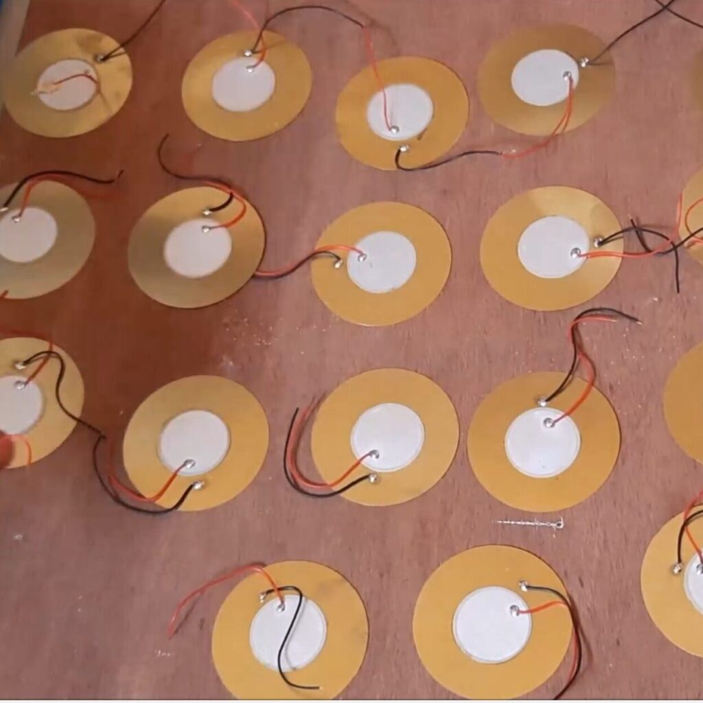
- Piezoelectric Transducers (PZT): These are the core components that convert mechanical energy from footsteps into electrical energy.
- Arduino Mega (CH340 Compact Type): This microcontroller reads the voltage output from the PZTs and controls other components.
- LCD Display: Used to show the voltage output in volts and percentage.
- Rechargeable Battery (4.2V 3800mAh LiPo): Stores the generated energy for later use.
- 12V DC Bulb: Acts as a load to demonstrate the practical application of the generated energy.
- LDR (Light Dependent Resistor): Senses ambient light levels to control the street light operation.
- PIR Sensor: Increases light intensity when motion is detected.
- ESP-01 Module: Sends data to an IoT platform for remote monitoring and control.
The Schematic Diagram: Setting Up the System

Explanation of the Schematic Diagram
The schematic diagram shows the connection of the piezo-electric transducers (PZTs) in the PZT generator design. We did both parallel and series connection for the PZTs. This was targeted to increase the A.C voltage output.
Steps involved in Assembling and Coupling The Piezo-electric Generator (Generate Electrical Energy with Footsteps Using Arduino)
Step 1: Assembling Piezoelectric Transducers

The first step in this project involves arranging multiple piezoelectric transducers under a surface where people will walk. The arrangement should ensure that each step applies pressure evenly across the transducers, maximizing energy generation.
Read More: How to Build An Over-Speeding Limit Project Arduino
Step 2: Programming and Connecting to Arduino
// include the library code:
#include <LiquidCrystal.h>
#include <EEPROM.h>
#include <BigCrystal.h>
#include <BigFont.h>
#include <SoftwareSerial.h>

// initialize the library with the numbers of the interface pins
LiquidCrystal lcd(9, 13, 22, 25, 27, 29);
BigCrystal bigCrystal(&lcd);

int volt;
float voltage1;

float low = 3.2;
float full = 10.0;
//for the ESP-01
#define gpio0 18  //used for software serial
#define gpio1 28
#define gpio2 20  //used for software serial
#define gpio3 30
//the serial comm.
SoftwareSerial arduino(gpio2, gpio0);
//for LDR
#define ldrPin A2
//for pirSensor
#define pirSensorPin 7
//for the transistor
#define transistorBase 11

// Define analog input for battery
#define ANALOG_IN_PIN A1
// Floats for ADC voltage & Input voltage
float adc_voltage = 0.0;
float in_voltage = 0.0;
// Floats for resistor values in divider (in ohms)
float R1 = 32380.0;
float R2 = 11760.0;
// Float for Reference Voltage
float ref_voltage = 5.0;
// Integer for ADC value
int adc_value = 0;

//define parameters for piezo generator
float R3 = 30000.0;
float R4 = 7500.0;
#define ANALOG_IN_PIN1 A0
// Floats for ADC voltage & Input voltage
float adc_voltage1 = 0.0;
float in_voltage1 = 0.0;
// Float for Reference Voltage
float ref_voltage1 = 5.0;
// Integer for ADC value
int adc_value1 = 0;
int readButton;


void setup() {
  // set up the LCD's number of columns and rows:
  lcd.begin(20, 4);
  Serial.begin(9600);
  arduino.begin(115200);
  //declare the inputs and outputs
  pinMode(transistorBase, OUTPUT);
  pinMode(pirSensorPin, INPUT);
  pinMode(ldrPin, INPUT);
  pinMode(gpio1, INPUT);
  pinMode(gpio3, INPUT);
  //write a welcome msg on lcd
  lcd.setCursor(2, 0);
  lcd.print("...WELCOME...");
  lcd.setCursor(3, 1);
  lcd.print("MR. BUKOLA ");
  delay(3000);
  lcd.clear();
  lcd.setCursor(4, 0);
  lcd.print("FOOT-STEP");
  lcd.setCursor(2, 1);
  lcd.print("PIEZOELECTRIC");
  lcd.setCursor(3, 2);
  lcd.print(" GENERATOR");
  lcd.setCursor(3, 30);
  lcd.print("  PROJECT");
  delay(3000);
  lcd.clear();
  for (int x = 0; x < 16; x++) {
    lcd.setCursor(0, 0);
    lcd.print("Checking Battery  ");
    lcd.setCursor(x, 1);
    lcd.print("*");
    delay(200);
  }
  lcd.clear();
}

float readBatteryVoltage() {
  // Read the Analog Input
  adc_value = analogRead(ANALOG_IN_PIN);

  // Determine voltage at ADC input
  adc_voltage = (adc_value * ref_voltage) / 1024.0;

  // Calculate voltage at divider input
  in_voltage = adc_voltage * (R1 + R2) / R2;

  // Print results to Serial Monitor to 2 decimal places
  // Serial.print("Input Voltage = ");
  // Serial.println(in_voltage, 2);
  return in_voltage;
}

float readPiezoGenVoltage() {
  // Read the Analog Input
  adc_value1 = analogRead(ANALOG_IN_PIN1);

  // Determine voltage at ADC input
  adc_voltage1 = (adc_value1 * ref_voltage1) / 1024.0;

  // Calculate voltage at divider input
  in_voltage1 = adc_voltage1 * (R3 + R4) / R4;

  // Print results to Serial Monitor to 2 decimal places
  // Serial.print("Input Voltage = ");
  // Serial.println(in_voltage1, 2);
  return in_voltage1;
}

int readOnlineStreetlightButton() {
  readButton = digitalRead(gpio1);
  Serial.print("Online Control Button: ");
  Serial.println(readButton);
  return readButton;
}

int checkNightTime() {
  readOnlineStreetlightButton();
  int checkLDR = analogRead(ldrPin);
  int checkPir = digitalRead(pirSensorPin);
  if (readButton == 1) {
    if (checkLDR < 200) {
      analogWrite(transistorBase, 25);
      if (checkPir == 1) {
        analogWrite(transistorBase, 255);
      }
    } else {
      digitalWrite(transistorBase, LOW);
    }
  }

  else {
  Serial.println("remote control disabled");
  }

  Serial.print("LDR reading: ");
  Serial.print(checkLDR);
  Serial.print(" PIR reading: ");
  Serial.println(checkPir);
}

void displayBattVoltage() {
  readBatteryVoltage();
  float batPercent = map(in_voltage, 0.11, 4.2, 0.0, 100.0);
  // Serial.print(batPercent);
  // Serial.println();
  batPercent = constrain(batPercent, 0, 99);
  // buffer to hold the converted variable having a length that is +1 of the variable lentgh
  char buffer[5];
  itoa(batPercent, buffer, 10);
  //dtostrf (floatVar, minStringWidthIncDecimalPoint, numVarsAfterDecimal, charBuf)
  // char buffer[5];
  //  dtostrf (batPercent, 0, 1, buffer);
  bigCrystal.printBig(buffer, 0, 0);
  bigCrystal.print("%");
  int number_count = 1;
  int number_temp = int(batPercent);
  while (number_temp != 0) {
    number_count++;
    number_temp /= 10;
  }
  number_count -= 1;
  if (batPercent < 1) { number_count = 1; }
  lcd.setCursor(0 + (number_count * 4), 0);
  bigCrystal.print(in_voltage);
  bigCrystal.print("V  ");
  lcd.setCursor(1 + (number_count * 4), 1);
  lcd.print(" BAT   ");


  Serial.print("Bat3 Percent:  ");
  Serial.print(batPercent);
  Serial.print("%");

  Serial.print(" Batt Voltage: ");
  Serial.print(in_voltage);  //print the voltge
  Serial.print("V");

  Serial.print(" Batt analogRead: ");
  Serial.println(adc_value);
}


void displayPiezoGen() {
  readPiezoGenVoltage();
  int readPiezoPin = analogRead(A0);
  // buffer to hold the converted variable having a length that is +1 of the variable lentgh
  char buffer[5];
  itoa(in_voltage1, buffer, 10);
  bigCrystal.printBig(buffer, 0, 2);
  bigCrystal.print("V");
  int number_count = 1;
  int number_temp = int(in_voltage1);
  while (number_temp != 0) {
    number_count++;
    number_temp /= 10;
  }
  number_count -= 1;
  if (in_voltage1 < 1) { number_count = 1; }
  lcd.setCursor(0 + (number_count * 4), 2);
  bigCrystal.print("  Piezo    ");
  lcd.setCursor(1 + (number_count * 4), 3);
  lcd.print(" Gen     ");
  Serial.print("Piezo Pin: ");
  Serial.print(readPiezoPin);
  Serial.print(" Piezo Voltage: ");
  Serial.print(in_voltage1);  //print the voltge
  Serial.println("V");
}


void loop() {
  checkNightTime();
  displayBattVoltage();
  displayPiezoGen();
  //send to the ESP01 dev board via serial comm.
  arduino.print(in_voltage);
  arduino.print("A");
  arduino.print(in_voltage1);
  arduino.print("B");
  arduino.print("\n");

  delay(1000);
  Serial.println("\n");
}
The voltage output from each piezoelectric transducer needs to be connected to the analog input pins of the Arduino Mega. This allows the microcontroller to read the voltage levels generated by foot traffic. The above code does the whole work, just connect your Arduino and upload the code.
Step 3: Displaying Voltage Output

Using an LCD display connected to the Arduino, you can visualize the voltage readings in real-time. This provides immediate feedback on how much energy is being generated with each step.
Step 4: Storing Energy

The generated electricity can be used to charge a rechargeable battery, ensuring that there is always a backup power source available for when foot traffic is low. The LiPo battery chosen for this project has a capacity of 3800mAh, making it suitable for storing significant amounts of energy.
Smart Street Light Integration
One of the innovative aspects of this project is its integration with smart street lighting technology.
Using LDRs for Day/Night Detection
The LDR detects ambient light levels and controls whether the street light should be on or off based on whether it is day or night. This automation helps conserve energy by ensuring that lights are only on when needed.
Enhancing Luminosity with PIR Sensors
The PIR sensor plays a crucial role in enhancing safety and visibility at night by increasing luminosity when motion is detected nearby. This feature not only saves energy but also ensures that pedestrians feel safer when walking through illuminated areas.
IoT Integration with ESP-01
To take this project a step further, integrating an ESP-01 module allows for remote monitoring and control via an IoT platform like Blynk.
Sending Data to IoT Platform

The ESP-01 can send real-time data regarding:
- Generated voltage from PZTs
- Battery charge status
- State of the street light (on/off)
This data can be accessed remotely, allowing users to monitor their system’s performance from anywhere.
Remote Control Functionality
With a user-friendly interface on the IoT platform, you can turn your smart street light on or off at will. This feature adds convenience and flexibility, enabling users to manage their lighting system effectively.
Testing The Project Design: Results and Analysis

The result of the project design here shows the voltage generated as it is being stepped on. Also the voltage of the backup battery.
Benefits of Generating Energy with Footsteps
Sustainability
Harnessing energy from footsteps contributes to sustainable practices by utilizing renewable resources—our daily movements—to generate power without depleting natural resources.
Cost-Effectiveness
This system reduces reliance on traditional power sources, potentially lowering electricity bills and maintenance costs associated with conventional street lighting systems.
Innovative Applications
Beyond street lighting, this technology can be applied in various settings such as:
- Public transportation hubs
- Shopping malls
- Parks and recreational areas
- Smart cities initiatives
Challenges and Considerations
While this project showcases exciting possibilities, there are challenges to consider:
Efficiency of Energy Conversion
The efficiency of piezoelectric transducers can vary based on design and material properties. It’s essential to choose high-quality PZTs for optimal performance.
Maintenance Requirements
Regular maintenance may be required to ensure that all components function correctly over time, especially in outdoor environments where exposure to elements can affect performance.
Future Prospects
As technology advances, we may see improvements in piezoelectric materials that enhance their efficiency and durability. Research into lead-free alternatives also presents exciting opportunities for environmentally friendly solutions.
Conclusion
The project “How to Generate Electrical Energy with Footsteps Arduino” exemplifies how innovative thinking can lead to sustainable solutions for everyday challenges. By harnessing mechanical energy from footsteps through piezoelectric transducers, we can create systems that not only generate electricity but also contribute positively to our environment. As we continue exploring renewable energy sources, projects like these pave the way toward smarter cities and more sustainable living practices.
FAQs
What are piezoelectric transducers?
- Piezoelectric transducers convert mechanical stress into electrical energy through the piezoelectric effect found in certain materials.
How does an Arduino read voltage from PZT?
- An Arduino reads voltage by connecting its analog input pins to the output terminals of piezoelectric transducers, allowing it to measure generated voltage levels.
Can I use this system indoors?
- Yes! While designed for outdoor applications like street lighting, this system can also be implemented indoors in high foot traffic areas like malls or airports.
What type of battery is used in this project?
- A 4.2V 3800mAh LiPo rechargeable battery is used for storing generated energy as backup power.
How does IoT integration enhance this project?
- IoT integration allows remote monitoring and control of systems via platforms like Zafron, providing real-time data on voltage generation and enabling users to manage street lights effectively from anywhere.


what is list of all need
Yes,
However, you can always chat us on WhatsApp or Telegram for more information.