The project design, IoT Smart Trash Bin has the following objectives: detecting the presence of human beings, opening the lead with no contact whatsoever, and allowing people to dispose of trash effectively. The trash can will be smart enough to check the depth of the trash that is inside it; then, once it is full, the bin won’t automatically open again for people to dispose of trash. But rather would send a beeping sound and direct them via their smart LCD screen to come back once it is empty again. Finally, it will notify the waste manager or administrator to come and dispose off its content via an online app.
IoT Smart Trash Bin Project: Components and Materials Needed
The table above contains the list of all the components used for the IoT Smart Trash Bin Project. Most of these components can be found on the Smartech online store.
Read More of Such Project Designs
- Arduino Smart Light Control Project Ideas
- Design Weather-Based and Temperature Controlled Automatic Window
- Design An RFID-Based Access Control with Disinfectant Booth
Schematic Diagram
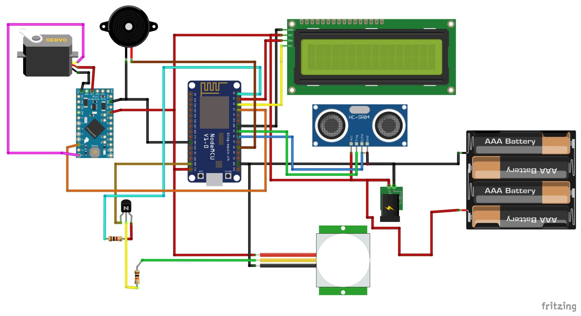
The circuit diagram shown above shows the connection of the NodeMCU to the sensors. The NodeMCU is using its GPIO pins to take the readings. The circuit diagram above illustrates the connection of the NodeMCU board to the peripherals of the design. The NodeMCU and other modules were powered by a 5V (4.8V) LiPo rechargeable battery.
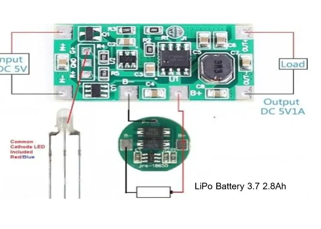
This is LiPo battery was charged by the LiPo charging module. It allowed the input of 5V from a type “B” USB power cord found on the side of the charging module. And has an output for powering load that can be regulated up to 18V. This is because the LiPo charging module has an onboard potentiometer that can be used to increase or decrease the output voltage. This was perfect for the design and had to be incorporated into the schematic.
Designing The Blynk App For IoT Monitoring
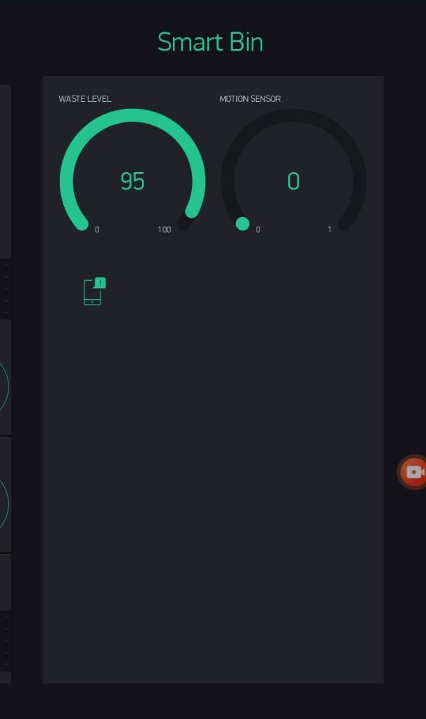
The app was done using the Blynk IoT dashboard. We used a widget to determine when the trash bin is full by using the ultrasonic sensor to map out the level of refuse in it at percentage level. We also added a notifier to trigger when the percentage level of the trash is within the range of 90–100%. There is also another gauge widget that shows when a motion is detected or not. As part of the programming, When the IoT Smart Trash Bin Project design is within the “Full” range, it notifies the admin through the app that the trash bin is filled up. And it doesn’t open up for users to use it any more. Thereby avoiding overfilling of the trash and littering by the sides of the trash bin.
IoT Smart Trash Bin Project: The Arduino Source Code
// Comment this out to disable prints and save space
#define BLYNK_PRINT Serial
#include <ESP8266WiFi.h>
#include <BlynkSimpleEsp8266.h>

#include <Wire.h>
#include <LiquidCrystal_I2C.h>
//create and instance of the LiquidCrystal, this name will be use as a class to call all the functions of the lcd library
LiquidCrystal_I2C lcd(0x27, 16, 2);


// Your WiFi credentials.
// Set password to "" for open networks.
#define Authorization_key "SL9bHBvYI1QpJp9VmDihQgWdhI8svjMr" //EExmWR-3B8jC7H0ttOzr9qmtAciGW8DR
char ssid[] = "AncII";
char pass[] = "eureka26";

BlynkTimer timer;

const int trigPin = D5; // Trigger Pin of Ultrasonic Sensor
const int echoPin = D6; // Echo Pin of Ultrasonic Sensor
long duration;
float distance;
//
#define pirPin D0
#define sensorPin  D3
#define piezoPin D8

int y;
int senseMotion;


int waste_volume(){
  digitalWrite(trigPin, LOW);
delayMicroseconds(2);
digitalWrite(trigPin, HIGH);
delayMicroseconds(10);
digitalWrite(trigPin, LOW);
duration = pulseIn(echoPin, HIGH);
distance = duration*0.034/2.0;

y = map(distance, 5.95, 37.70, 100, 0);
y = constrain(y, 0, 100);
 //display on LCD
 lcd.setCursor(0,0);
 lcd.print("  WASTE LEVEL:");
  lcd.setCursor(6,1);
 lcd.print(y);
 lcd.print(" %       ");

 Serial.print("dist: ");
 Serial.print(distance);
 Serial.print("cm, ");
 Serial.print("height: ");
 Serial.print(y);
 Serial.println(" %");
  return y, distance;


}


int motionSensor(){
  senseMotion = digitalRead(pirPin);
  Serial.print("motion: ");
  Serial.println(senseMotion);
  return senseMotion;
 }


void sendSensor(){

 Blynk.virtualWrite(V0, y);
 Blynk.virtualWrite(V1, senseMotion);
}


void setup(){
  // Debug console
  Serial.begin(115200);

pinMode(trigPin, OUTPUT);
pinMode(echoPin, INPUT);
pinMode(piezoPin, OUTPUT);
pinMode(pirPin, INPUT);
pinMode(sensorPin, OUTPUT);

digitalWrite(piezoPin, LOW);

Blynk.begin(Authorization_key, ssid, pass);

  lcd.init();   // initialize the lcd
  Wire.begin(); // Start the I2C
  // Turn on the blacklight and print a message.
  lcd.backlight();//turn on the lcd backlight
  lcd.setCursor(0,0);
  lcd.print("    WELCOME   ");// ouput the text on the lcd screen
   lcd.setCursor(0,1);
  lcd.print("  MR. GBOYEGA ");// ouput the text on the lcd screen
        delay(3000);
     lcd.clear();
    lcd.setCursor(0,0);
    lcd.print("IoT BASED SMART");
    lcd.setCursor(0,1);
     lcd.print("  REFUSE PROJET");
    delay(3000);
     lcd.clear();
    lcd.setCursor(0,0);
    lcd.print("Connected to:");
    lcd.setCursor(5,1);
     lcd.print(ssid);
     delay(3000);
     lcd.clear();

    // Setup a function to be called every second
  timer.setInterval(1000L, sendSensor);
    Serial.println("hello");
    Serial.println("end");
}


bool close_bin(){
  digitalWrite(sensorPin, LOW);
  Serial.print(sensorPin);
  lcd.setCursor(0,0);
  lcd.print("*Closing Bin.**   ");
  delay(2000);
  lcd.setCursor(0,1);
  lcd.print(" Please Wait....");
     lcd.clear();
    //delay(500);

  delay(1000);
  return false;
}

//
bool open_bin(int count = 5){
  digitalWrite(sensorPin, HIGH);
  Serial.println(sensorPin);
  lcd.setCursor(0,0);
  lcd.print("*Opening Bin.**   ");
  lcd.setCursor(0,1);
  lcd.print(" Please Wait....");
  delay(2000);
  lcd.setCursor(0,0);
  lcd.print("                     ");
  while(count > 0){
    lcd.setCursor(8,0);
    lcd.print(count);
    count -= 1;
    delay(1000);
  }
  return false;
}


void loop(){
  waste_volume();
  motionSensor();
 delay(500);

 if((y < 89) && (senseMotion == 1)){
   open_bin();
   close_bin();
 }

//
 if(y >= 90){
  if(senseMotion == 1){
    Blynk.notify("Hello Admin, Smart Bin Full. Pls dispose People want to use it.");
    digitalWrite(piezoPin, HIGH);
    lcd.setCursor(0,0);
    lcd.print("  SORRY BIN FULL ");
    lcd.setCursor(0,1);
    lcd.print("  PLS COME BACK ");
    delay(3000);
    digitalWrite(piezoPin, LOW);
    lcd.clear();
  }
 }


  Blynk.run();
  timer.run();

}
Explanation of the Arduino Source Code
The Source code above can be downloaded from Github for free. The Arduino code begins with importing the various libraries that we needed for the project design. These libraries included the ESP8266 lib and the Blynk lib for ESP8266. Since we were using the I2C module, we included the lib for it too.
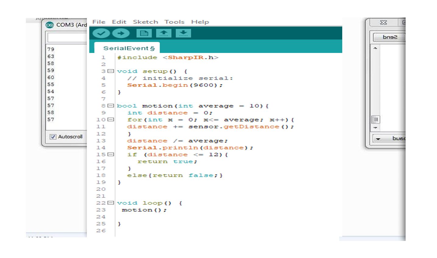
The code included the sharpIR library way help in calculating the distance of objects from the sensor. A custom function called motion() was used to calculate such distanced measured from the objects. A for loop was used to take iterated measurements 10 times and the average of these measurements taken. This was shown in code line 10 through 13. This distance measured was printed on serial monitor in code line 14. A Boolean integer was returned when the distance measured was less or equal to 12. The loop called this function repeatedly.
Testing and Results
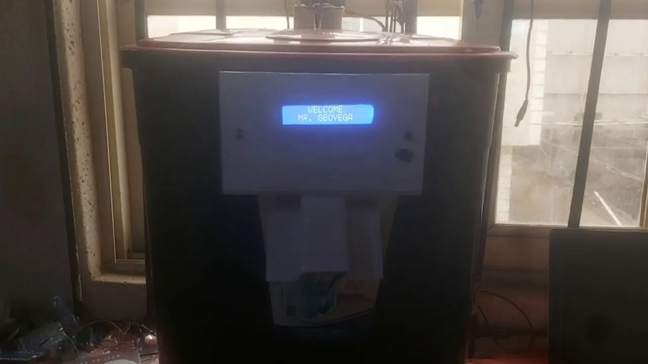
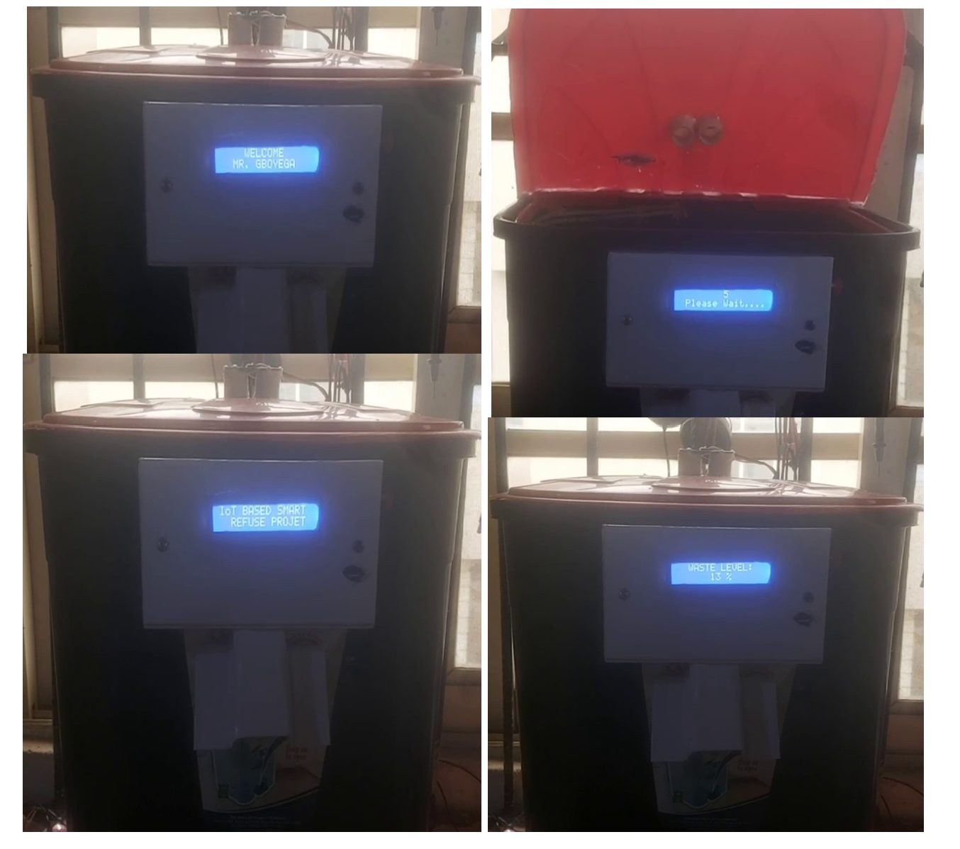
On turning on the design, it displays the welcome message on the LCD screen as shown above, this welcome message lasts for about 3 seconds. after which it fades out.
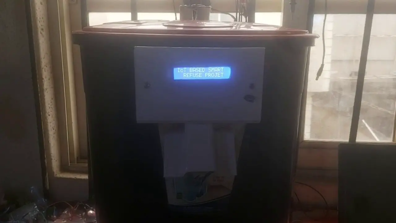
Next, is the displaying of the project design name on the LCD screen. This give the project design a more aesthetic look and feel.
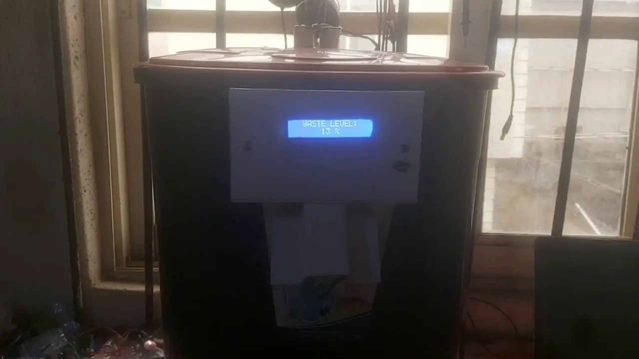
The IoT smart trash bin project displays the level of the waste inside its container. Thereby telling the user or admin the current waste level. This is very important for visualization.
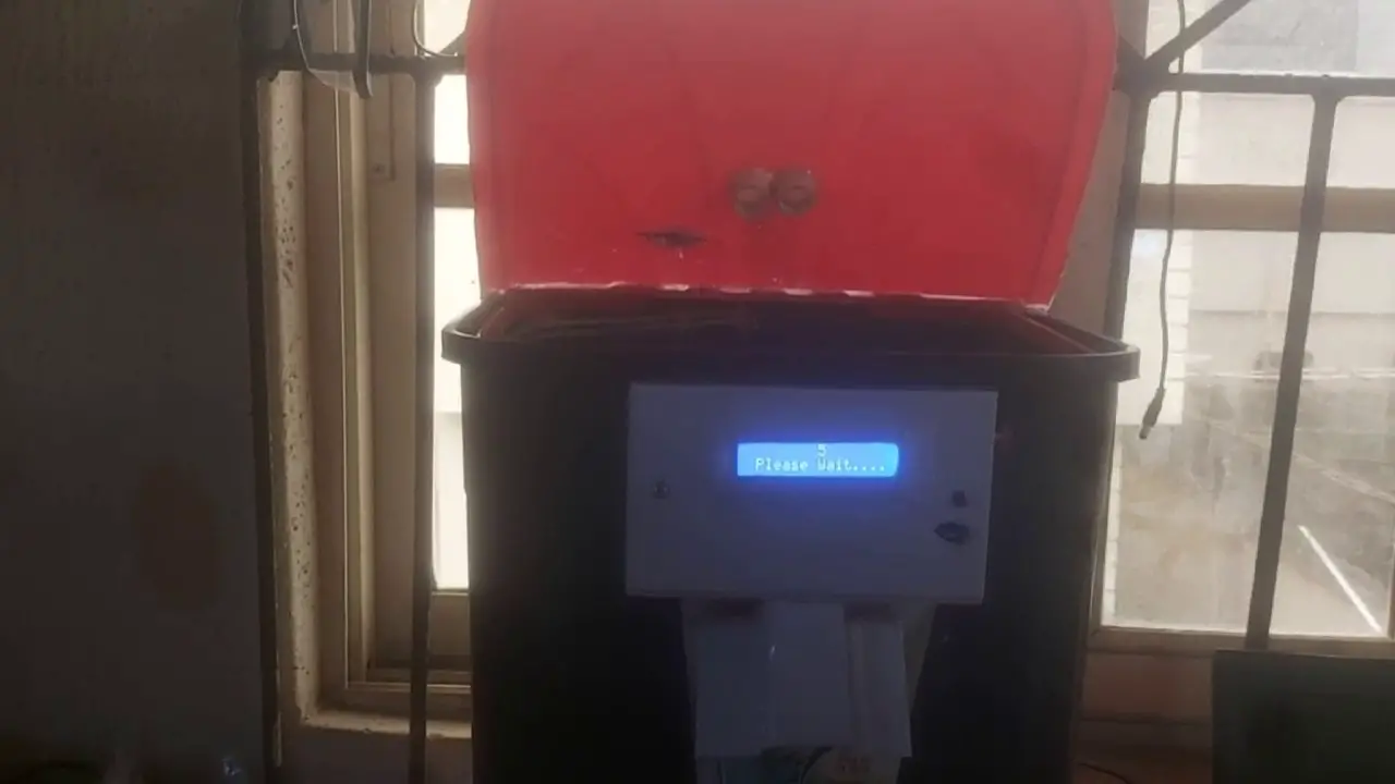
When motion is sensed around the project design, and it the waste level isn’t filled up, it will automatically open the lid cover and stay open for 5 second for the user to dispose off his or her waste. After the the countdown reaches 0, it will automatically close the lid.
Conclusion
We have designed and constructed an Arduino based IoT Smart trash bin project that has the capacity to automatically detect the presence of user that wants to dispose off waste, open for use, closes afterwards. It can detect when the bin is full and send an app notification to the admin and while on this, it would remain closed.
Let us know in the comment section if this project design was able to assist you in any way. Leave us a message if you require any help al

